Ver. Q1
All Rights Reserved. Copyright 2019
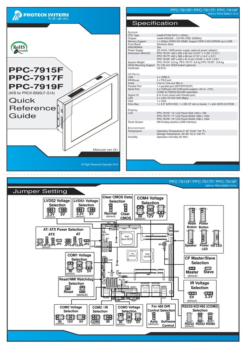
Specification
SP-S216
Quick
Reference
Guide
SP-S216
SP-S216
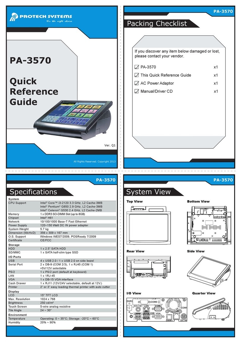
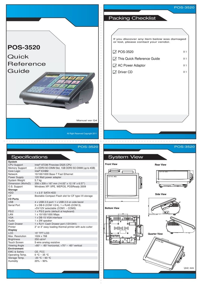
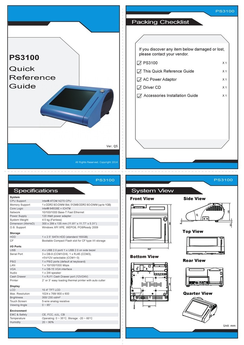
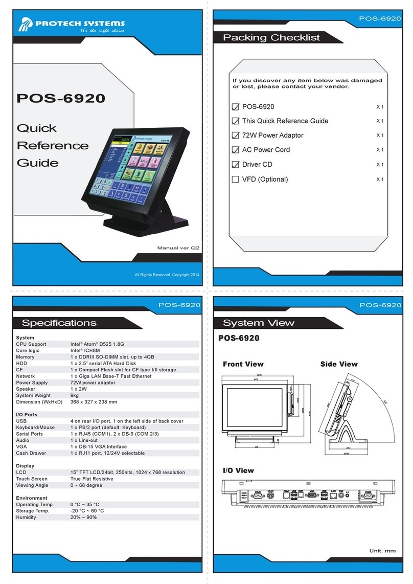
System
CPU Type Intel®Core™i7-7700T, Quad Core, 2.9GHz, 8M cache
Intel®Core™i5-7500T, Quad Core, 2.7GHz, 6M cache
Intel®Core™i3-7101TE, Dual Core, 3.4GHz, 3M cache
Intel®Core™i7-6700TE, Quad Core, 2.4GHz, 8M cache
Intel®Core™i5-6500TE, Quad Core, 2.3GHz, 6M cache
Intel®Core™i3-6100TE, Dual Core, 2.7GHz, 4M cache
Intel®Pentium®G4400TE,Dual Core, 2.4GHz, 3M cache
Intel®Celeron®G3930TE, Dual Core, 2.7GHz, 2M cache
Intel®Celeron®G3900TE, Dual Core, 2.3GHz, 2M cache
Memory Support 2 x DDR4 2133MHz SO-DIMM sockets (up to 32 GB)
Storage 2 x 2.5” SATAIII SSD (support RAID 0/1 in Q170 SKU only)
Front Bezel Stainless steel (SUS 304)
IP65 Yes (for front panel only)
Power Input DC In 9~36V
Operating System Windows 10 loT Enterprise 2019 LTSC 64bit / LTSB 2016 64bit
Ubuntu16.04 LTS
System Weight 12.8kg
Dimensions (WxHxD) 585 x 377 x 131.7mm
Mounting Support Wall Mount / VESA 100 / Panel Mount
Watchdog 1~255 seconds watchdog timer selectable
Certifications FCC/CE
I/O Ports
Display 1 x DVI-I (DVI-D+VGA)
USB 4 x USB 3.0
Serial Ports COM 3/4 for RS232
COM1/2 for RS-232/422/485 selectable under BIOS
[COM 1/2 for +5V/+12V/RI selectable by jumper]
Antenna Holes 3 x antenna holes
Expansion Slots 1 x full-sized Mini PCIe (Mini PCIe, USB and SIM signals)
1 x half-sized Mini PCIe (Mini PCIe and USB signals)
1 x SIM card slot / 1 x CFast slot
LAN 2 x GbE LAN, Wake-On-LAN, PXE,
LAN 1: Intel®PHY 219LM (10/100/1000 Mbps)
LAN 2: Intel®LAN 210AT (10/100/1000 Mbps)
2 x PoE (IEEE 802.3af), max.15.4W for each port
Audio 1 x Line In / 1 x Line Out / 1 x Mic In
Power On/Off 1 x power button, 1 x remote switch
LED 2 x PoE active LED (optional)
I2C 1 x I2C Bus port (optional)
Display
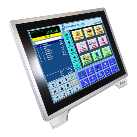
LCD 21.5” True Flat TFT LCD(LED) resolution FHD (16:9) 1920x1080
Touchscreen Projected capacitive touchscreen (USB interface)
Environment
Operating Temp. HDD: 0°C ~ 45°C(32°F~113°F)
(Ambient with airflow) SSD: 0°C ~ 40°C (32°F~104°F)
Storage Temp. -20°C ~ 80°C (-4°F ~ 176°F)
Humidity 20% ~ 90%
Jumper Setting
CFast Voltage Control Selection
1
1
HDDLED1
CAUTION! Danger of explosion may occur if the battery is replaced incorrectly.
Replace batteries only with the same or equivalent type recommended
by the manufacturer. Dispose the used batteries according to the
manufacturer’s instructions.
3.3V 5V
1
(default)
Flash Descriptor Override
Selection
Disable
1
1
Enable
BIOS Recovery Mode
Selection
Normal
1
Recovery
1
RI
+12V
+5V
6
2
6
2
6
2
(default)
0.95V (default)
Normal
(default)
LVDS Resolution Selection
1920x1080
2CH/24bit
(default)
JP1
5
6
1
2
JP2
5
6
1
2
LVDS Voltage Selection
5
6
1
2
5
6
1
2
+3.3V (default)
+5V
(default)
(default)
JP15JP12
5
1
2
1
6
2
2
5
1
6
2
5
1
2
6
2
2
1.0V
1
Clear CMOS
1
DVI1
COM3
COM4
COM1
COM2
Hardware Power Failure Selection
Disable
(default)
Enable
1
1
JP4
56
1
2
1
5
2
6JP15
JP12
12
JP7 13
DIO1
115
216
1
3
2
4ATX_PWR1
1 3
JP17
LED1
PWR_IN1
LAN1USB1
AUDIO1
12
3
4
I2C1
1
2
JP16
M_PCIE1
PWR_BTN1
PWR_BTN2
SATA2
SATA_PWR2
SATA1
PWRLED1
SO-DIMM1
M_PCIE2
CMOS1
1
2
15
16
17
18 52
51
1
2
15
16
17
18
51
52
2
20
1
1
2
2
LAN2
12
COM1 Pin9 and COM2 PIN18
Definition Selection Guide
5
5
1
5
1
VCCIO Voltage Selection
Clear CMOS Data Selection
1
LVDS1
12
2930
INV1
1
6
1
2
5
6
JP1
1
2
6
5
JP2
5
6
1
JP3
2
1 1
7171
SGN_BRD1
1 2
19 20
SATA_PWR1
RST_SW1
1 3
JP9
CFAST1
JLPC1
PCI_E1
1
19
S1 PC17
1
2
1
2
