R&G LP0263BK User manual

Page 1of 19 LP0263
R&G
Unit 1, Shelley’s Lane, East Worldham, Alton, Hampshire, GU34 3AQ
Tel: +44 (0)1420 89007 Fax: +44 (0)1420 87301 www.rg-racing.com Email: info@rg-racing.com
FITTING INSTRUCTIONS FOR LP0263BK LICENCE PLATE BRACKET
KAWASAKI VERSYS 1000 2019
THIS KIT CONTAINS THE ITEMS PICTURED AND LABELLED BELOW.
DO NOT PROCEED UNTIL YOU ARE SURE ALL PARTS ARE PRESENT.
Please note that the way the kit is packed does not necessarily represent the way of mounting to the bike.
THE PARTS SHOWN MAY BE REPRESENTATIVE ONLY (FOR CLARITY OF INSTRUCTIONS ONLY).
Please note that in cases where kits are packed with rubber washers holding the components onto the bolt – the
rubber washers should be thrown away!
Digital copies of these instructions are available to download from www.rg-racing.com

Page 3of 19 LP0263
R&G
Unit 1, Shelley’s Lane, East Worldham, Alton, Hampshire, GU34 3AQ
Tel: +44 (0)1420 89007 Fax: +44 (0)1420 87301 www.rg-racing.com Email: info@rg-racing.com
LEGEND
ITEM 1 = LICENCE PLATE BRACKET (TB0263) (x1)
ITEM 2 = LICENCE PLATE ILLUMINATOR ASSEMBLY (x1)
ITEM 3 = INDICATOR ADAPTORS (I0026) (x4)
ITEM 4 = RUBBER GASKET (RG0015) (x1)
ITEM 5 = M6 WASHER (x8)
ITEM 6 = M6 x 1.00mm x 20mm BUTTON HEAD BOLT (x4)
ITEM 7 = M6 NYLOC NUT (x4)
ITEM 8 = LICENCE PLATE ILLUMINATOR CONNECTOR (CON0051) (x1)
ITEM 9 = INDICATOR CONNECTOR (CON0060) (x2)
ITEM 10 = SMALL CABLE TIES (x3)
ITEM 11 = 200MM LENGTH OF LARGE HEATSHRINK (x6)
ITEM 12 = REFLECTOR (x1)
TOOLS REQUIRED
•Set of metric Allen keys.
•Philips head screwdriver.
•Socket set to include 10mm and 14mm A-F sockets and wrench.
•Small amount of adhesive.
MAXIMUM TORQUE SETTINGS
•M4 BOLT = 8Nm
•M5 BOLT = 12Nm
•M6 BOLT = 15Nm
•M8 BOLT = 20Nm
•M10 BOLT = 40Nm
Picture 1
Picture 2

Page 7of 19 LP0263
R&G
Unit 1, Shelley’s Lane, East Worldham, Alton, Hampshire, GU34 3AQ
Tel: +44 (0)1420 89007 Fax: +44 (0)1420 87301 www.rg-racing.com Email: info@rg-racing.com
Picture 21
Picture 22
FITTING INSTRUCTIONS
•Remove the seat, using the lock under the tail.
•Remove the bolts/clip arrowed in Pictures 2-6, and carefully remove the LH side fairing.
•Repeat on the RH side (shown in Picture 7).
•With both side fairings removed, remove the four bolts arrowed in Picture 8, and carefully remove the luggage
rack.
•UseaPhilips screwdriver to remove the two bolts arrowed in Picture 9.
•Remove the two bolts arrowed in Picture 10.
•Repeat on the other side.
•Locate the licence plate illuminator and indicator connectors (arrowed in Picture 11) and disconnect them
(shown in Picture 12).
•While supporting the licence plate mount, remove the four bolts shown in Picture 13.
•Carefully feed the wiring through the bike, taking note of the route (Picture 14).
•Remove the licence plate mount from the bike.
If fitting OEM indicators (Ignore this section if fitting mini indicators)
•With the licence plate mount removed, remove the bolts arrowed in Pictures 15-17.
•Carefully separate the two halves of the licence plate mount, shown in Picture 18.
•Before removing the indicators, take note which indicator is LH and RH.
•Using a Philips head screwdriver, remove the bolt on the rear of the indicator.
•Carefully remove the OEM indicator (making sure any plates, washers, and plastic inserts are put to one side for
later use) by gently pulling it out of the licence plate mount.
•Repeat for the other indicator.

Page 8of 19 LP0263
R&G
Unit 1, Shelley’s Lane, East Worldham, Alton, Hampshire, GU34 3AQ
Tel: +44 (0)1420 89007 Fax: +44 (0)1420 87301 www.rg-racing.com Email: info@rg-racing.com
•Refit the indicators to the tail tidy (ITEM 1), by gently pushing the indicator into the two profiled slots on the
bracket (shown in Picture 19) NOTE: some washing up liquid may help with this. Be sure to reuse the plates,
washers, and plastic inserts removed during a previous step.
If fitting mini indicators (Ignore this section if fitting OEM indicators)
•Slide two lengths of heat shrink (ITEM 11) over the exposed wiring of the mini indicator, and heat gently to
shrink it.
•Slide one of the indicator adaptors (ITEM 3) over the thread of the mini indicator, ensuring the profiled side of
the adaptor is outward facing.
•Insert the assembly into the profiled slot in the tail tidy (ITEM 1), highlighted in Picture 19.
•Then slide another indicator adaptor (ITEM 3) over the thread, ensuring the profiled edge goes into the profiled
slot in the tail tidy.
•Secure the mini indictor in position using the M8 nut provided.
•Connect one of the Indicator connectors (ITEM 9) to the end of mini indicator using the bullet connectors.
•Repeat the steps above for the other indicator.
NOTE: 1 x set of RGR0001 resistors (available separately) may be required to achieve the correct flash rate.
•Slide two lengths of heat shrink (ITEM 11) over the exposed wiring of the licence plate illuminator assembly
(ITEM 2), and heat gently to shrink it.
•Fit the licence plate illuminator assembly (ITEM 2) to the tail tidy (ITEM 1) using the bolts, washers and nuts
provided. Please note you will have to fit the light shroud and use a small amount of adhesive to hold it in
position.
•Connect the licence plate illuminator connector (ITEM 8) to the end of the licence plate illuminator using the
bullet connectors.
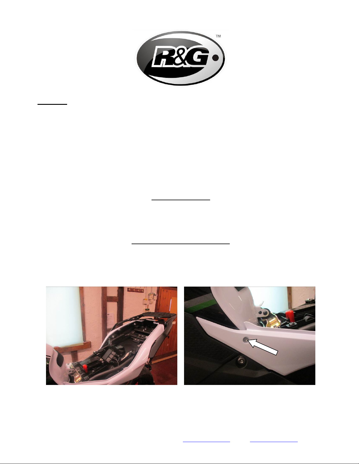
•Neatly secure the wiring to the tail tidy (ITEM 1) using the cable ties (ITEM 10) in the holes arrowed in Picture
20.
NOTE: Ensure the wiring passes through the large hole at the top of the tail tidy.
•Slide the rubber gasket (ITEM 4) over the wiring and position it so the four mounting holes line up.
•Offer the assembly up and feed the wiring through the bike, following the same route as the original wiring.
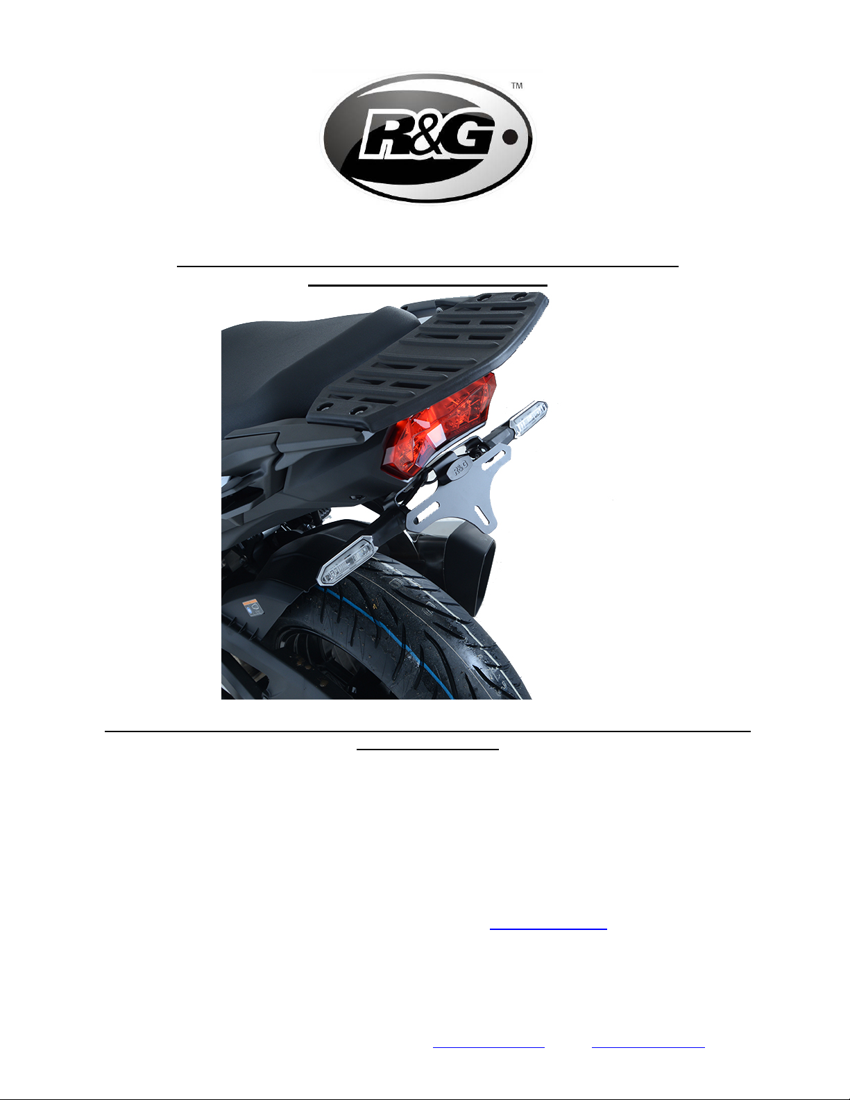
•Secure the tail tidy in place using the M6 bolts, washers and nyloc nuts (as shown in Picture 21).
•Connect the indicator and licence plate illuminator connectors to the wiring loom.
•Refit the bolts removed in Picture 10, luggage rack, two side fairings and seat.
•Refit the licence plate to the tail tidy (ITEM 1) (it may require drilling).
•Please check the operation of all lights before riding the motorcycle. If illumination fails swap the bullet
connectors.
•IMPORTANT: IF FITTING A FULL-SIZE LICENCE PLATE AND PLACING IT FAR DOWN ON
THE LICENCE PLATE HANGER, THERE IS A SMALL CHANCE OF THE LICENCE PLATE
HITTING THE BACK WHEEL UNDER HEAVY LOAD AND OVER LARGE BUMPS IN THE ROAD.
IT IS YOUR RESPONSIBILITY TO CHECK FOR THIS POSSIBILITY AND TAKE AVOIDING
ACTION. FAILURE TO CHECK THIS COULD RESULT IN SERIOUS INJURY.
•Depending on local laws, attach enclosed reflector (ITEM 12) in an appropriate location.
ISSUE 1 23/01/2019 (LF)

Page 9of 19 LP0263
R&G
Unit 1, Shelley’s Lane, East Worldham, Alton, Hampshire, GU34 3AQ
Tel: +44 (0)1420 89007 Fax: +44 (0)1420 87301 www.rg-racing.com Email: info@rg-racing.com
CONSUMER NOTICE
The catalogue description and any exhibition of samples are only broad indications of the Products and R&G may make design changes which do not
diminish their performance or visual appeal and supplying them in such state shall conform to the order. The Buyer acknowledges no representation or
warranty (other than as to title) has been given or will apply to the Products other than those in R&G’s order or confirmation and the Buyer confirms it
has chosen the Products as being of merchantable quality and suitable for its particular purposes. Where R&G fits the Products or undertakes other
services it shall exercise reasonable skill and care and rectify any fault free of charge unless the workmanship has been disturbed. The Buyer is
responsible for ensuring that the warranty on the motorcycle is not affected by the fitting of the Products. On return of any defective Products R&G
shall at its option either supply a replacement or refund the purchase money but shall not be liable if the Products have been modified or used or
maintained otherwise than in accordance with R&G’s or manufacturer’s instructions and good engineering practice or if the defect arises from accident
or neglect. Other than identified above and subject to R&G not limiting its liability for causing death and personal injury, it shall not be liable for
indirect or consequential loss and otherwise its liability shall be limited to the amounts paid by the Buyer for the Products or the fitting or service
concerned. These terms do not affect the Buyer’s statutory rights.
R&G RETURNS POLICY (NON-FAULTY GOODS)
Returns must be pre-authorised (if not pre-authorised the return will be rejected). Goods may only be returned direct to us if they were purchased direct
from us (customer must prove if necessary). Otherwise to be returned to original vendor. Goods must be in re-sellable condition, in the opinion of
R&G. All returns are subject to a 25% restocking and handling fee (25% of the gross value exc. P&P – at the prevailing price at time of purchase). The
customer must pay any and all carriage charges. No returns of discontinued products, unless within 14 days of purchase. This policy does not affect
your statutory rights and does not refer to faulty goods.

Page 10 of 19 LP0263
R&G
Unit 1, Shelley’s Lane, East Worldham, Alton, Hampshire, GU34 3AQ
Tel: +44 (0)1420 89007 Fax: +44 (0)1420 87301 www.rg-racing.com Email: info@rg-racing.com
NOTICE DE MONTAGE POUR LP0263BK SUPPORT DE PLAQUE
KAWASAKI VERSYS 1000 2019
Le kit contient les articles exposés ci-dessous, vérifier que toutes les pièces soient présentes avant de
procéder au montage.
La façon dont le kit est emballé ne correspond pas forcément à la façon de monter les pièces sur la moto.
LES PARTIES PRESENTEES PEUVENT ETRE UNIQUEMENT REPRESENTATIVES (POUR LA
CLARTÉ DES INSTRUCTIONS UNIQUEMENT).
Notez que si les kits sont emballés avec des rondelles en caoutchouc servant à tenir les composants, ces rondelles
doivent être jetées !
Notice disponible au téléchargement sur www.rg-racing.com

Page 12 of 19 LP0263
R&G
Unit 1, Shelley’s Lane, East Worldham, Alton, Hampshire, GU34 3AQ
Tel: +44 (0)1420 89007 Fax: +44 (0)1420 87301 www.rg-racing.com Email: info@rg-racing.com
LÉGENDE
ARTICLE 1 = SUPPORT DE PLAQUE (TB0263) (x1)
ARTICLE 2 = ASSEMBLAGE FEU DE PLAQUE (x1)
ARTICLE 3 = ADAPTATEURS CLIGNOTANT (I0026) (x4)
ARTICLE 4 = JOITN EN CAOUTCHOUC (RG0015) (x1)
ARTICLE 5 = M6 RONDELLE (x8)
ARTICLE 6 = M6 x 1.00mm x 20mm BOULON (x4)
ARTICLE 7 = M6 ÉCROU (x4)
ARTICLE 8 = CONNECTEUR DE FEU DE PLAQUE (CON0051) (x1)
ARTICLE 9 = CONNECTEUR DE CLIGNOTANT (CON0060) (x2)
ARTICLE 10 = PETITS COLLIERS DE SERRAGE (x3)
ARTICLE 11 = 200MM MANCHON THERMO RÉTRACTABLE (x6)
ARTICLE 12 = RÉFLECTEUR (x1)
OUTILS REQUIS
•Clés Allen.
•Tournevis cruciforme.
•Clé à cliquet + douilles 10mm et 14mm.
•Un peu d’adhésif.
VALEURS DE SERRAGE RECOMMANDÉES
•M4 BOULON = 8Nm
•M5 BOULON = 12Nm
•M6 BOULON = 15Nm
•M8 BOULON = 20Nm
•M10 BOULON = 40Nm
NOTICE DE MONTAGE
•Enlever le siège, en ouvrant le verrou sous le support.
•Enlever les boulons/le clip indiqué sur la photo 2-6, puis enlever délicatement le carénage côté gauche.
•Répéter cette action du côté droit (voir Photo 7).
•Une fois les 2 carénages enlevés, enlever les 4 boulons indiqués sur la photo 8, puis enlever le porte bagages.
•Utiliser un tournevis cruciforme pour enlever les 2 boulons indiqués sur la photo 9.
•Enlever les 2 boulons indiqués sur la photo 10.
•Répéter de l’autre côté.
•Placer le feu de plaque et les connecteurs de clignotant (voir photo 11) puis déconnectez les (voir photo 12).
•Tout en supportant le support de plaque, enlever les 4 boulons indiqués sur la photo 13.
•Passer le fil dans la moto, en notant le cheminement (Photo 14).
•Enlever le support de plaque de la moto.
Si vous montez les clignotants d’origine (ignorer cette section si vous montez les mini clignotants)
•Une fois le support de plaque enlevé, enlever les boulons indiqués sur la photo 15-17.
•Séparer les 2 moitiés du support de plaque, voir photo 18.
•Avant d’enlever les clignotants, prenez notre de la correspondance du clignotant gauche et droit.
•Utiliser un tournevis cruciforme pour enlever le boulon à l’arrière du clignotant.

Page 13 of 19 LP0263
R&G
Unit 1, Shelley’s Lane, East Worldham, Alton, Hampshire, GU34 3AQ
Tel: +44 (0)1420 89007 Fax: +44 (0)1420 87301 www.rg-racing.com Email: info@rg-racing.com
•Enlever le clignotant d’origine (veiller à bien mettre de côté les plaques, rondelles et inserts plastiques de côté
pour une réutilisation ultérieure) en le tirant doucement du support de plaque.
•Répéter cette action pour l’autre clignotant.
•Remonter les clignotants sur le support de plaque (ARTICLE 1), en poussant le clignotant dans les 2 fentes
profilées du support (voir Photo 19) NOTE : Pour faciliter cette opération, vous pouvez utiliser un peu de
produit vaisselle. Veiller à réutiliser les plaques, rondelles et inserts plastique inserts enlevés dans les étapes
précédentes.
Si vous montez les mini clignotants (Ignorer cette partie si vous montez les clignotants d’origine)
•Glissez 2 longueurs de manchon thermos rétractables (ARTICLE 11) sur l’extrémité du fil du mini clignotant
puis chauffer pour rétreindre.
•Glisser un des adaptateurs de clignotant (ARTICLE 3) sur le filetage du mini clignotant, en veillant à ce que la
partie profilée de l’adaptateur soit orientée vers l’extérieur.
•Insérer l’ensemble dans la fente profilée sur support (ARTICLE 1), surlignée sur la photo 19.
•Ensuite, glisser un autre adaptateur de clignotant (ARTICLE 3) sur le filetage, en veillant à ce que le bord fileté
se place dans la fente profile du support de plaque.
•Fixer le mini clignotant en position en utilisant l’écrou M8 fourni.
•Connecter un des connecteurs de clignotant (ARTICLE 9) sur l’extrémité du mini clignotant en utilisant les
connecteurs.
•Répéter les étapes précédentes pour l’autre clignotant.
NOTE : 1 x kit de résistances RGR0001 (disponible séparément) peuvent être nécessaires pour obtenir un bon
niveau d’éclairage.
•Glisser 2 longueurs de manchon thermos rétractable (ARTICLE 11) sur l’extrémité du fil de feu de plaque
(ARTICLE 2), puis chauffer pour rétreindre.
•Monter le feu de plaque (ARTICLE 2) sur le support de plaque (ARTICLE 1) en utilisant les boulons, rondelles
et écrou fournis. Notez que vous devrez monter le linceul de feu puis utiliser un peu d’adhésif pour le fixer en
place.
•Connecter le connecteur de feu de plaque (ARTICLE 8) sur l’extrémité du feu de plaque à l’aide des
connecteurs.
•Fixer les fils sur le support (ARTICLE 1) en utilisant les colliers de serrage (ARTICLE 10) dans les trous
indiqués sur la photo 20.
NOTE : Veiller à ce que le fil passe dans le trou large situé sur le haut du support.
•Glisser le joint en caoutchouc (ARTICLE 4) sur le fil puis positionnez le de façon à ce que les 4 trous de fixation
soient alignés.
•Monter l’ensemble puis passer le fil dans la moto, en suivant le même chemin que le fil d’origine.
•Fixer le support de plaque en place en utilisant les boulons M6, rondelles et écrous (voir photo 21).
•Connecter le clignotant et les connecteurs de feu de plaque au faisceau de fils.
•Remonter les boulons enlevés sur la photo 10, le porte bagages, les 2 carénages et le siège.
•Remonter la plaque d’immatriculation sur le support de plaque (ARTICLE 1) (peut nécessiter un perçage).
•Tester l’ensemble des feux avant de prendre la route. Si l’éclairage échoue, permutez les connecteurs.
•IMPORTANT : Si vous installez une grosse plaque, il y a un risque que la plaque entre en
contact avec la roue arrière en cas de choc sur la route (bosse, grosse charge etc..). Il est de
votre responsabilité de vérifier que cela ne puisse pas se produire. Ne pas effectuer ces
vérifications peut entrainer des dommages ainsi que des blessures graves pour le pilote.
•Selon les lois locales, attacher le réflecteur rouge (article 12) à l’endroit approprié.

Page 14 of 19 LP0263
R&G
Unit 1, Shelley’s Lane, East Worldham, Alton, Hampshire, GU34 3AQ
Tel: +44 (0)1420 89007 Fax: +44 (0)1420 87301 www.rg-racing.com Email: info@rg-racing.com
ISSUE 1 23/01/2019 (LF)
CONSUMER NOTICE
The catalogue description and any exhibition of samples are only broad indications of the Products and R&G may make design changes which do not
diminish their performance or visual appeal and supplying them in such state shall conform to the order. The Buyer acknowledges no representation or
warranty (other than as to title) has been given or will apply to the Products other than those in R&G’s order or confirmation and the Buyer confirms it
has chosen the Products as being of merchantable quality and suitable for its particular purposes. Where R&G fits the Products or undertakes other
services it shall exercise reasonable skill and care and rectify any fault free of charge unless the workmanship has been disturbed. The Buyer is
responsible for ensuring that the warranty on the motorcycle is not affected by the fitting of the Products. On return of any defective Products R&G
shall at its option either supply a replacement or refund the purchase money but shall not be liable if the Products have been modified or used or
maintained otherwise than in accordance with R&G’s or manufacturer’s instructions and good engineering practice or if the defect arises from accident
or neglect. Other than identified above and subject to R&G not limiting its liability for causing death and personal injury, it shall not be liable for
indirect or consequential loss and otherwise its liability shall be limited to the amounts paid by the Buyer for the Products or the fitting or service
concerned. These terms do not affect the Buyer’s statutory rights.
R&G RETURNS POLICY (NON-FAULTY GOODS)
Returns must be pre-authorised (if not pre-authorised the return will be rejected). Goods may only be returned direct to us if they were purchased direct
from us (customer must prove if necessary). Otherwise to be returned to original vendor. Goods must be in re-sellable condition, in the opinion of
R&G. All returns are subject to a 25% restocking and handling fee (25% of the gross value exc. P&P – at the prevailing price at time of purchase). The
customer must pay any and all carriage charges. No returns of discontinued products, unless within 14 days of purchase. This policy does not affect
your statutory rights and does not refer to faulty goods.

Page 15 of 19 LP0263
R&G
Unit 1, Shelley’s Lane, East Worldham, Alton, Hampshire, GU34 3AQ
Tel: +44 (0)1420 89007 Fax: +44 (0)1420 87301 www.rg-racing.com Email: info@rg-racing.com
MONTAGEANLEITUNG FÜR LP0263BK KENNZEICHENHALTER
KAWASAKI VERSYS 1000 2019
ALLE GELIEFERTEN TEILE SIND UNTEN ABGEBILDET UND GEKENNZEICHNET. BEVOR SIE MIT
DER MONTAGE BEGINNEN, ÜBERPRÜFEN SIE SORGFÄLTIG, DASS ALLE TEILE VORHANDEN SIND.
Hinweis: Die Verpackung der Teile stellt nicht die Reihenfolge der Montage dar.
DIE UNTEN ABGEBILDETEN TEILE DIENEN LEDIGLICH ZUR ERKLÄRUNG
Hinweis für Kits mit Plastikunterlegscheiben an den Schrauben – Diese Plastikunterlegscheiben werden nicht für
Eine digitale Version dieser Montageanleitung kann auf folgender Seite heruntergeladen werden:
www.rg-racing.com

Page 17 of 19 LP0263
R&G
Unit 1, Shelley’s Lane, East Worldham, Alton, Hampshire, GU34 3AQ
Tel: +44 (0)1420 89007 Fax: +44 (0)1420 87301 www.rg-racing.com Email: info@rg-racing.com
LIEFERUMFANG
ARTIKEL 1 = KENNZEICHENHALTER (TB0263) (x1)
ARTIKEL 2 = KENNZEICHENBELEUCHTUNG (x1)
ARTIKEL 3 = ADAPTER FÜR BLINKER (I0026) (x4)
ARTIKEL 4 = GUMMIDICHTUNG (RG0015) (x1)
ARTIKEL 5 = M6 UNTERLEGSCHEIBE (x8)
ARTIKEL 6 = M6 x 1,00mm x 20mm INBUSSCHRAUBE (x4)
ARTIKEL 7 = M6 SELBSTSICHERNDE MUTTER (x4)
ARTIKEL 8 = VERBINDUNG FÜR DIE KENNZEICHENBELEUCHTUNG (CON0051) (x1)
ARTIKEL 9 = VERBINDUNG FÜR DEN BLINKER (CON0060) (x2)
ARTIKEL 10 = KLEINE KABELBINDER (x3)
ARTIKEL 11 = 200MM SCHRUMPFSCHLAUCH (x6)
ARTIKEL 12 = RÜCKSTRAHLER (x1)
SIE BENÖTIGEN FOLGENDES:
•Satz Inbusschlüssel
•Kreuzschlitzschraubenzieher
•Satz Steckschlüssel mit 10 und 14mm Steckschlüssel
•etwas Sekundenkleber
MAXIMALE ANZUGSDREHMOMENTE:
M4 SCHRAUBE = 8Nm
M5 SCHRAUBE = 12Nm
M6 SCHRAUBE = 15Nm
M8 SCHRAUBE = 20Nm
M10 SCHRAUBE = 40Nm
MONTAGEANLEITUNG
•Entfernen Sie den Sitz (das Schloss befindet sich unter dem Heck).
•Entfernen Sie die Schrauben und den Clip, die in den Abbildungen 2-6 abgebildet sind, und entfernen Sie die
linke Seitenverkleidung.
•An der rechten Seite wiederholen (siehe Abbildung 7).
•Wenn beide Seitenverkleidungen abmontiert sind, entfernen Sie die vier Schrauben, die in Abbildung 8
abgebildet sowie den Gepäckträger vom Motorrad.
•Benutzen Sie einen Kreuzschlitzschraubenzieher, um die zwei Schrauben, die in Abbildung 9 markiert sind, zu
entfernen.
•Entfernen Sie die zwei Schrauben, die in Abbildung 10 gekennzeichnet sind.
•An der anderen Seite wiederholen.
•Orten Sie die Verbindungen für die Kennzeichenbeleuchtung und die Blinker (siehe Abbildung 11) und trennen
Sie diese (siehe Abbildung 12).
•Stützen Sie den Kennzeichenhalter und entfernen Sie die vier Schrauben, die in Abbildung 13 abgebildet sind.
•Die Verkabelung durch das Motorrad führen und die Verlegung der Kabel notieren (Abbildung 14).
•Entfernen Sie den Kennzeichenhalter vom Motorrad.

Page 18 of 19 LP0263
R&G
Unit 1, Shelley’s Lane, East Worldham, Alton, Hampshire, GU34 3AQ
Tel: +44 (0)1420 89007 Fax: +44 (0)1420 87301 www.rg-racing.com Email: info@rg-racing.com
Wenn Sie die Originalblinker montieren (diesen Abschnitt ignorieren, wenn Sie Miniblinker montieren)
•Nachdem der Kennzeichenhalter entfernt wurde, entfernen Sie die Schrauben, die in den Abbildungen 15 – 17
markiert sind.
•Die zwei Hälften des Kennzeichenhalters vorsichtig auseinander ziehen – siehe Abbildung 18.
•Bevor Sie sie entfernen, notieren Sie an welcher Seite die Blinker montiert sind.
•Benutzen Sie einen Kreuzschlitzschraubenzieher, um die Schraube hinten am Blinker zu entfernen.
•Den original Blinker vorsichtig entfernen, indem Sie ihn vorsichtig vom Kennzeichenhalter rausziehen (bitte
achten Sie darauf, dass alle Platten, Unterlegscheiben und Kunststoffteile zur Seite gelegt – diese werden für den
späteren Wiederanbau benötigt).
•Diese Schritte mit dem zweiten Blinker wiederholen.
•Montieren Sie die Blinker am Kennzeichenhalter (Artikel 1)wieder - die Blinker vorsichtig in die zwei Schlitze
an der Halterung einführen (siehe Abbildung 19). HINWEIS: etwas Spülmittel kann diesen Schritt vereinfachen.
Bitte die Platten, Unterlegscheiben und Kunststoffteile, die während des vorherigen Schritts entfernt wurden,
wieder montieren.
Wenn Sie Miniblinker montieren (Diesen Abschnitt ignorieren, wenn Sie die original Blinker montieren).
•Zwei x Schrumpfschlauch (Artikel 11) an der offenen, hervorstehenden Verkabelung des Miniblinkers
anbringen, und mit leichter Hitze schrumpfen.
•Einen Blinker-Adapter (Artikel 3) über das Gewinde des Miniblinkers schieben, sodass die Seite mit Profil nach
außen gerichtet ist.
•Die Einheit in den Schlitz (mit Profil) im Kennzeichenhalter (Artikel 1) einsetzen (in Abbildung 19
gekennzeichnet).
•Einen zweiten Adapter (Artikel 3) über das Gewinde schieben, sodass die Kante mit Profil in den Schlitz (mit
Profil) im Kennzeichenhalter passt.
•Benutzen Sie die M8 Mutter vom Kit, um den Miniblinker in Position zu befestigen.
•Verbinden Sie eine der Verbindungen für die Blinker (Artikel 9) mit dem Ende des Miniblinkers – benutzen Sie
hierfür einen Kabelverbinder.
•Wiederholen Sie die oben beschriebenen Schritte mit dem zweiten Blinker.
HINWEIS: 1 x Satz RGR0001 Widerstände (separat erhältlich) wird eventuell benötigt, um die richtige
Blitzgeschwindigkeit zu erzielen.
•Zwei x Schrumpfschlauch (Artikel 11) an der offenen, hervorstehenden Verkabelung der
Kennzeichenbeleuchtung (Artikel 2) anbringen, und mit leichter Hitze schrumpfen.
•Benutzen Sie die Schrauben, Unterlegscheiben und Muttern vom Kit, um die Kennzeichenbeleuchtung (Artikel
2) am Kennzeichenhalter (Artikel 1) zu montieren. Bitte beachten Sie, dass etwas Sekundenkleber benötigt wird,
um die Lichtabdeckung in Position zu befestigen.
•Benutzen Sie die Kabelverbindung, um den Verbinder für die Kennzeichenbeleuchtung (Artikel 8) am Ende der
Kennzeichenbeleuchtung zu verbinden.
•Die Kabel ordentlich am Kennzeichenhalter (Artikel 1) mit den Kabelbindern befestigen (Artikel 10) an den in
Abbildung 20 gekennzeichneten Öffnungen.
HINWEIS: bitte achten Sie darauf, dass die Verkabelung durch die große Öffnung oben am Kennzeichenhalter
passt.
•Schieben Sie die Gummidichtung (Artikel 4) über die Verkabelung und positionieren, sodass die vier
Montageöffnungen bündig sind.
•Die Einheit ans Motorrad ansetzen und die Kabel wie ursprünglich durch das Motorrad verlegen.
•Den Kennzeichenhalter mit den M6 Schrauben, Unterlegscheiben und selbstsichernden Muttern in Position
befestigen – siehe Abbildung 21.

Page 19 of 19 LP0263
R&G
Unit 1, Shelley’s Lane, East Worldham, Alton, Hampshire, GU34 3AQ
Tel: +44 (0)1420 89007 Fax: +44 (0)1420 87301 www.rg-racing.com Email: info@rg-racing.com
•Verbinden Sie die Verbindungen für die Blinker und die Kennzeichenbeleuchtung am Kabelbaum.
•Montieren Sie die Schrauben wieder, die in Abbildung 10 entfernt wurden, sowie den Gepäckträger, die zwei
Seitenverkleidungen und den Sitz.
•Montieren Sie das amtliche Kennzeichen wieder am Kennzeichenhalter (Artikel 1) (Bohrungen im Kennzeichen
evtl. notwendig).
•Überprüfen Sie die Funktion der Beleuchtung (Blinker und Kennzeichenhalter-Beleuchtung) vor Gebrauch des
Fahrzeuges.
•WICHTIG: WENN EIN GROSSES KENNZEICHEN ZU WEIT NACH UNTEN MONTIERT WIRD,
BESTEHT BEI SCHWERER LAST ODER DURCH GROSSE BODENWELLEN EIN GERINGES RISIKO,
DASS DAS KENNZEICHEN AN DAS HINTERRAD STOSSEN KANN. ES LIEGT IN IHRER
VERANTWORTUNG DIES ZU ÜBERPRÜFEN UND, WENN NOTWENDIG, ENTSPRECHENDE
VORBEUGENDE MASSNAHMEN ZU ERGREIFEN. DIE NICHTBEACHTUNG DIESES
SICHERHEITSHINWEIS KANN ZU SCHWEREN VERLETZUNGEN FÜHREN.
•Entsprechend der gesetzlichen Vorschriften, den mitgelieferten Rückstrahler (Artikel 12) anbringen.
AUSGABE 1 23/01/2019 (LF)
CONSUMER NOTICE
The catalogue description and any exhibition of samples are only broad indications of the Products and R&G may make design changes which do not diminish their performance or visual appeal and
supplying them in such state shall conform to the order. The Buyer acknowledges no representation or warranty (other than as to title) has been given or will apply to the Products other than those in
R&G’s order or confirmation and the Buyer confirms it has chosen the Products as being of merchantable quality and suitable for its particular purposes. Where R&G fits the Products or undertakes other
services it shall exercise reasonable skill and care and rectify any fault free of charge unless the workmanship has been disturbed. The Buyer is responsible for ensuring that the warranty on the
motorcycle is not affected by the fitting of the Products. On return of any defective Products R&G shall at its option either supply a replacement or refund the purchase money but shall not be liable if the
Products have been modified or used or maintained otherwise than in accordance with R&G’s or manufacturer’s instructions and good engineering practice or if the defect arises from accident or neglect.
Other than identified above and subject to R&G not limiting its liability for causing death and personal injury, it shall not be liable for indirect or consequential loss and otherwise its liability shall be
limited to the amounts paid by the Buyer for the Products or the fitting or service concerned. These terms do not affect the Buyer’s statutory rights.
R&G RETURNS POLICY (NON-FAULTY GOODS)
Returns must be pre-authorised (if not pre-authorised the return will be rejected). Goods may only be returned direct to us if they were purchased direct from us (customer must prove if necessary).
Otherwise to be returned to original vendor. Goods must be in re-sellable condition, in the opinion of R&G. All returns are subject to a 25% restocking and handling fee (25% of the gross value exc. P&P
– at the prevailing price at time of purchase). The customer must pay any and all carriage charges. No returns of discontinued products, unless within 14 days of purchase. This policy does not affect your
statutory rights and does not refer to faulty goods.
Table of contents
Languages:
Other R&G Motorcycle Accessories manuals