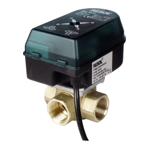
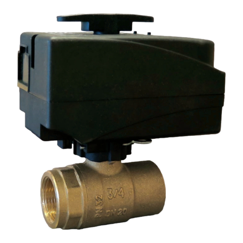
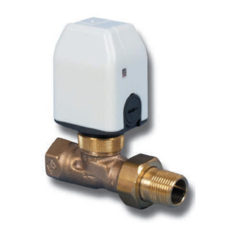
Resol VA20 User manual

Vielen Dank für den Kauf dieses RESOL-Gerätes.
Bitte lesen Sie diese Anleitung sorgfältig durch, um die
Leistungsfähigkeit dieses Gerätes optimal nutzen zu können.
*48004340*
48004340
D
RESOLVA20
Montage- und Bedienungsanleitung
www.resol.de
VA20
Handbuch
D
Manual
B
Manuel
Manual
Manuale

VA20
© RESOL 08280 va20.mon5s.indd
|2
D
Inhaltsverzeichnis
Sicherheitshinweise..................................................................................2
Konformitätserklärung ............................................................................2
Technische Daten .....................................................................................3
1. Installation...........................................................................................4
1.1 Montage .......................................................................................................4
1.2 Elektrischer Anschluss ..............................................................................4
2. Bedienung............................................................................................5
2.1 Umstellung auf „stromlos offen“............................................................5
2.2 Rückstellung auf „stromlos geschlossen“.............................................6
3. Hubanzeige .........................................................................................6
4. Anwendungsbeispiele.........................................................................7
Impressum ................................................................................................8
Sicherheitshinweise
Bitte beachten Sie diese Sicherheits-
hinweise genau, um Gefahren und
Schäden für Menschen und Sach-
werte auszuschließen.
Vorschriften
Beachten Sie bei Arbeiten
- die gesetzlichen Vorschriften zur
Unfallverhütung,
- die gesetzlichen Vorschriften zum
Umweltschutz,
- die Bestimmungen der Berufsge-
nossenschaft,
- die einschlägigen Sicherheitsbe-
stimmungen der DIN, EN, DVGW,
TRGI,TRF und VDE
Diese Anleitung richtet sich aus-
schließlich an autorisierte Fach-
kräfte.
- Elektroarbeiten dürfen nur von
Elektrofachkräften durchgeführt
werden.
- Die erstmalige Inbetriebnahme
hat durch den Ersteller der Anlage
oder einen von ihm benannten
Fachkundigen zu erfolgen.
Bestimmungsgemäße Verwen-
dung
Das Durchgangsventil RESOL VA20
ist zur Schaltung von Volumen-
strömen in der Solar- und Wärme-
pumpentechnik unter Berücksichti-
gung der in dieser Anleitung angege-
benen technischen Daten bestimmt.
Die bestimmungswidrige Verwen-
dung führt zum Ausschluss jeglicher
Haftungsansprüche.
Irrtum und technische Änderungen vorbehalten
Konformitätserklärung
Das Produkt entspricht den relevanten Richtlinien
und ist daher mit der CE-Kennzeichnung verse-
hen. Die Konformitätserklärung kann bei RESOL
angefordert werden.

VA20
© RESOL 08280 va20.mon5s.indd
3 |
D
Einsatzbereich:
Das Durchgangsventil RESOL VA20 findet Anwendung
bei der Schaltung von Volumenströmen in der Solar- und
Wärmepumpentechnik.
Arbeitsweise:
Ab Werk ist das Ventil VA20 im stromlosen Zustand ge-
schlossen.DasVentil kann jedoch auch in einfachen Schritten
in den umgekehrten Ausgangszustand gebracht werden. Die
Verstellung erfolgt über einen elektrothermischen Stellan-
trieb mit einer Stellzeit von ca. 3 Minuten. Dadurch erfolgt
die Volumenstromregelung wasserschlagfrei. Die Lieferung
des RESOLVA20 erfolgt komplett mit Anschlussverschrau-
bungen aus Messing.
Technische Daten Stellantrieb:
Versorgung:
230V~, 50...60Hz
Leistungsaufnahme: max. 2,5W
i max: 150 mA
Umgebungstemperatur: max. 50°C
Federkraft: 125 N
Hub: 4,5 mm
Schutzart:
IP 42 bei waagerechtem Einbau
IP 44 bei senkrechtem Einbau nach oben
Schutzklasse: II
Stellzeit: ca. 3 min.
Verschmutzungsgrad: 2
Werkseinstellung: stromlos geschlossen
Technische DatenVentil:
Temperaturbereich: bis 120°C,
temperaturbeständig, kurzzeitig bis 140°C
Material:
Ventilgehäuse: korrosionsbeständiger Rotguss
Innenteile: Messing und nichtrostender Stahl
Dichtungen: EPDM
Maximaler Betriebsdruck: 10 bar
Lieferbare Gewindeanschlüsse:
VA20: ½“, ¾“, 1“ und 1¼“
DN 15 20 25 32
L 95 106 118 135
H 21,5 21,5 23 23
Rp 1/2 3/4 1 1 1/4
SW 30 37 47 52
kvs (m3/h) 1,35 2,50 4,20 5,80

VA20
© RESOL 08280 va20.mon5s.indd
|4
D
1. Installation
Die Anschlussverdrahtung ist nach dem entsprechenden
Schaltplan in der Schaltschemenübersicht durchzuführen.
Die Leitungen des Stellantriebes an die Relaisausgänge des
Reglers anschließen:
• diebrauneLeitungandieKlemmemitPhaseanschließen.
• dieblaueLeitungandieKlemmemitdemNeutralleiter
anschließen
Eine Absicherung der einzelnen Geräte ist zu empfehlen.
Der Leiterquerschnitt soll bei 220V Betriebsspannung den
einschlägigen örtlichen undVDE-Richtlinien entsprechen,bei
24V jedoch mindestens 1,5mm².
Wichtig: Betriebs- und Steuerspannung müssen gleich
sein.
Beim Betrieb mehrerer Ventile mit Stellantrieb in einer
Anlage unbedingt auf Phasengleichheit achten!
Für die Zugentlastung des Anschlusskabels ist eine Stopf-
buchsenverschraubung zu verwenden, die nach fertiger
Installation des Anschlusses fest anzuziehen ist.
Bei Verlegung der Anschlussleitung darauf achten,
dass diese nicht in Wärmekontakt mit heißen
Anlagenteilen (z.B. Radiator, Rohrleitungen etc.)
steht.
NachAnschluss der Leitung an den Regler oderThermostaten
ist der Stellantrieb einsatzfähig.
1.1 Montage
• DenStellantriebmitHilfederÜberwurfmutteraufdem
Ventil befestigen. Das Ventil kann waagerecht oder senk-
recht eingebaut werden, jedoch nicht mit dem Antrieb
nach unten.
1.2 Elektrischer Anschluss
Die Montage des Ventils ist nach den einschlägigen Regeln
der Technik vorzunehmen. Die Montage darf nur vom
Fachmannausgeführtwerden!DieeinschlägigenVDE+TÜV
Vorschriften sind zu beachten!
braun blau
blau braun

VA20
© RESOL 08280 va20.mon5s.indd
5 |
D
2.1 Umstellung auf „stromlos offen“
1. Transparente Abdeckung der Hubanzeige mit Hilfe eines
Schlitzschraubendrehers vom Gehäuse entfernen.
2. Hubanzeige mit einer Zange aus dem Gehäuse ziehen.
3. Schwarze Arretierscheibe mit einer Zange aus der Unter-
seite des Stellantriebes ziehen.
4. Mit einem Schlitzschraubendreher die Handverstellung
herunterdrücken und den Schraubendreher um etwa 60°
nach links drehen.Die Handverstellung befindet sich dann
in der in Bild 4b gezeigten Position.
5. Die Hubanzeige und anschließend die transparente Ab-
deckung einsetzen.
Die Arretierscheibe nicht wieder einsetzen, jedoch aufbe-
wahren.
1. 2.
3. 4a.
5.
4b.
2. Bedienung Der Stellantrieb verfügt über einen Handschalter, der mit
einem Schraubendreher betätigt werden kann. Mit diesem
Handschalter können zwei Betriebszustände eingestellt
werden:
• stromlosoffen
• stromlosgeschlossen
WARNUNG!
Vor der Umstellung den Stellan-
trieb von der Spannungsversor-
gung trennen!

VA20
© RESOL 08280 va20.mon5s.indd
|6
D
3. Hubanzeige
Die Hubanzeige hinter der transparentenAbdeckung an der
Frontseite des Stellantriebes zeigt an, wie weit der Stellan-
trieb geöffnet ist.Sie dient damit der Funktionsüberwachung
des Stellantriebes:
Läuft die Anzeige nach ca. 3 Minuten anliegender Betriebs-
spannung auf die Position „offen“, so arbeitet das Gerät
einwandfrei.Trennt man den Stellantrieb von der Spannung,
muss die Hubanzeige innerhalb von ca. 3 Minuten die Po-
sition „geschlossen“ anzeigen.
Position „geschlossen“
Die Hubanzeige ist nur am unteren Rand sichtbar: Der
Stellantrieb hält dasVentil geschlossen.
Position „offen“
Die Hubanzeige ist am oberen Rand sichtbar: Der Stellan-
trieb hält dasVentil geöffnet.
2.1 Rückstellung auf „stromlos geschlossen“
1. Transparente Abdeckung der Hubanzeige vom Gehäuse
entfernen und die Hubanzeige aus dem Gehäuse ziehen
2. Mit einem Schlitzschraubendreher die Handverstellung
herunterdrücken und den Schraubendreher um etwa 60°
nach rechts drehen. Die Handverstellung befindet sich
dann in der in Bild 2b gezeigten Position.
3.Die Arretierscheibe in die Unterseite einsetzen.
Hubanzeige und anschließend die transparenteAbdeckung
einsetzen.
1. 2a.
3.
2b.

4.Anwendungsbeispiele
1 Kollektor, 3 Speicher, wahlweise Beladung 1 Kollektor, 2 Speicher mit Speicherrücklaufanhebung

Wichtiger Hinweis
Die Texte und Zeichnungen dieser Anleitung entstanden
mit größtmöglicher Sorgfalt und nach bestem Wissen. Da
Fehler nie auszuschließen sind, möchten wir auf folgendes
hinweisen:
Grundlage Ihrer Projekte sollten ausschließlich eigene Be-
rechnungen und Planungen an Hand der jeweiligen gültigen
Normen und DIN-Vorschriften sein.Wir schließen jegliche
Gewähr für dieVollständigkeit aller in dieser Anleitung ver-
öffentlichten Zeichnungen undTexte aus, sie haben lediglich
Beispielcharakter. Werden darin vermittelte Inhalte benutzt
oder angewendet, so geschieht dies ausdrücklich auf das
eigene Risiko des jeweiligen Anwenders. Eine Haftung des
Herausgebers für unsachgemäße,unvollständige oder falsche
Angaben und alle daraus eventuell entstehenden Schäden
wird grundsätzlich ausgeschlossen.
Anmerkungen
Das Design und die Spezifikationen können ohneVorankün-
digung geändert werden.
Die Abbildungen können sich geringfügig vom Produktions-
modell unterscheiden.
Impressum
Diese Montage- und Bedienungsanleitung einschließlich aller
seinerTeile ist urheberrechtlich geschützt. EineVerwendung
außerhalb des Urheberrechts bedarf der Zustimmung der
Firma RESOL - Elektronische Regelungen GmbH. Dies gilt
insbesonderefürVervielfältigungen/Kopien,Übersetzungen,
Mikroverfilmungen und die Einspeicherung in elektronischen
Systemen.
Herausgeber: RESOL - Elektronische Regelungen GmbH

Thank you for buying this RESOL product.
Please read this manual carefully to get the best performance from this unit.
D
RESOLVA20
Mounting and operating instructions
www.resol.de
VA20
Manual
EN

VA20
© RESOL 08280 va20.mon5s.indd
|10
EN
Inhaltsverzeichnis
Safety advice...........................................................................................10
Declaration of conformity.....................................................................10
Technical data.........................................................................................11
1. Installation.........................................................................................12
1.1 Mounting....................................................................................................12
1.2 Electrical conection.................................................................................12
2. Operation..........................................................................................13
2.1 Adjustment to „normally open“...................................................................... 13
2.2 Adjustment to „normally closed“.................................................................... 14
3. Stroke indicator................................................................................14
4. Examples ...........................................................................................15
Imprint ..............................................................................................16
Safety advice
Please pay attention to the follow-
ing safety advice in order to avoid
danger and damage to people and
property.
Instructions:
Attention should be paid to
- valid local regulations
- the statutory provisions for pre-
vention of industrial accidents,
- the statutory provisions for envi-
ronmental protection,
- the Health and Safety atWork Act
1974
- Part P of the Building Regulations
2005
- BS7671 Requirements for electri-
cal installations and relevant safety
regulations of DIN, EN, DVGW,
TRGI,TRF and VDE.
These instructions are exclusively
addressed to authorised skilled
personnel.
- Only qualified electricians should
carry out installation and mainte-
nance work.
- Initial installation should be carried
out by named qualified personnel
Appropriate usage
The 2-port valve RESOL VA20 is
used for switching flow rates in solar
thermal and heat pump systems in
compliance with the technical data
specified in these instructions.
Improper use excludes all liability
claims
Subject to change.Errors excepted.
Declaration of conformity
The product complies with the relevant direc-
tives and is therefore labelled with the CE mark.
The Declaration of Conformity is available upon
request, please contact RESOL.
VA20
© RESOL 08280 va20.mon5s.indd
11 |
EN
Area of application:
The 2-port valve RESOL VA20 is used for switching flow
rates in solar thermal and heat pump technology.
Characteristics:
The valve RESOL VA20 is delivered closed when current-
less.The initial state of the valve can be easily inverted. It
is operated by an electro-thermic actuator (with manual
emergency operation) and has an operation time of appro-
ximately 3 min.This way there is no back stroke within the
tube system throughout volume fl ow regulation. RESOL
VA20 valve comes with connection screws made of brass.
Technical data actuator
Power supply:
230V~, 50...60Hz
Power consumption max. 2,5W
i max: 150 mA
Ambient temperature:
max. 50°C
Spring force: 125 N
Stroke: 4,5 mm
Protection type:
IP 42 when mounted horizontally
IP 44 when mounted vertically to the top
Protection class: II
Actuation time: ca. 3 min.
Degree of pollution: 2
Factory setting: normally open
Technical data valve:
Temperature range: up to 120°C,
temporarily up to 140°C
Material:
Vlave body: corrosion-resistant red bronze
Internal parts: brass and corrosion resistant steel
Seal: EPDM
Maximum pressure: 10 bar
Connection thread:
VA20: ½“, ¾“, 1“ and 1¼“
DN 15 20 25 32
L 95 106 118 135
H 21,5 21,5 23 23
Rp 1/2 3/4 1 1 1/4
SW 30 37 47 52
kvs (m3/h) 1,35 2,50 4,20 5,80

VA20
© RESOL 08280 va20.mon5s.indd
|12
EN
1. Installation
The connection has to be carried out in accordance with
the connecion scheme shown in the overview.
The cables of the actuator have to be connected to the relay
outputs of the controller:
• connectthebrownlinetotheterminalwiththephase.
• connectthebluelinetotheterminalwiththeneutralcon-
ductor
We recommend fusing the individual devices.The cable sec-
tion should correspond to the valid local regulations at 220V
operating voltage and should be at least 1,5 mm² at 24V.
Important note: Operating voltage and control voltage
must be equal.
When several valves with actuators are used in one system,
the voltages must be in-phase.
Use a stuffing box screwing as a strain relief of the connec-
tion cable. Tighten the screwing after the installation has
been finished.
During routing of the cable, the connection cable
must not touch hot system components (e.g. radia-
tor, pipes, etc.)
After the cables have been connected to the controller or
thermostat, the actuator is ready for operation.
1.1 Mounting
• Attachtheelectrothermalactuatortothevalvebymeans
of a union nut.The valve can be mounted in any position,
but the actuator must not face downwards.
1.2 Electrical connection
The installation of the valve must be carried out in accor-
dance with the approved technical regulations.The installation
must be carried out by an approved technician! Pay attention
to the valid loacal regulations!
brown blue
blue brown

VA20
© RESOL 08280 va20.mon5s.indd
13 |
EN
2.1 Adjustment to „normally open“
1. Remove the transparent cover of the stroke indicator
from the housing using a flat-headed scew driver.
2.Remove the stroke indicator from the housing using
pliers.
3. Remove the black blocking disc from the lower part of
the actuator using pliers.
4. Press down the manual adjustment device by means of
a flat headed screw driver and turn the screw driver by
60° to the left.The manual adjustment device is then in
the position shown in figure 4.b.
5. Insert the stroke indicator and then the transparent cover.
Do not insert the blocking disc, but do not throw it away.
1. 2.
3. 4a.
5.
4b.
2. Operation The actuator is equipped with a manual adjustment device
which can be operated by means of a screw driver. Two
operating modes can be adjusted using this manual adjust-
ment device:
•normallyopen
•normallyclosed
WARNING!
Disconnect the actuator from
the power supply before chan-
ging the setting!

VA20
© RESOL 08280 va20.mon5s.indd
|14
EN
3. Stroke indicator
The stroke indicator behind the transparanet cover at the
front of the actuator indicates how far the valve is opened.
It is used as a function control of the actuator.
When the indicator is in the „open“ position after the operating
voltage has been applied to the valve for approx.3 minutes,the
unit operates without any fault.When the unit is disconnec-
ted from the power supply, it must return to the „closed“
position within approx. 3 minutes.
„Closed“ position
The indicator is visibe at the lower edge of the window:the
electrothermal actuator keeps the valve closed.
„Open“ position
The indicator is visibe at the upper edge of the window:the
electrothermal actuator keeps the valve open.
2.2 Adjustment to„normally closed“
1. Remove the transparent indicator cover from the housing
and remove the indicator.
2. Press down the manual adjustment device by means of
a flat headed screw driver and turn the screw driver by
60° to the right.The manual adjustment device is then in
the position shown in figure 2.b.
3. Insert the blocking disc into the lower part. Insert indica-
tor and then transparent cover.
1. 2a.
3.
2b.

4. Examples
1 collector, 3 stores, store sequence choice 1 collector, 2 stores with store return preheating

Please note:
The design and the specifications are to be changed without notice.
The illustrations may differ from the original product.
Reprinting / copying
This mounting- and operation manual including all parts is
copyrighted. Another use outside the copyright requires
the approval of RESOL - Elektronische Regelungen GmbH.
This especially applies for copies, translations, micro films
and the storage into electronic systems.
Editor: RESOL - Elektronische Regelungen GmbH
Important notice:
We took a lot of care with the texts and drawings of this
manual and to the best of our knowledge and consent.As
faults can never be excluded, please note:Your own calcu-
lations and plans, under consideration of the current stan-
dards and DIN-directions should only be basis for your
projects.We don´t offer a guarantee for the completeness
of the drawings and texts of this manual - they only repre-
sent some examples. They can only be used at your own
risk. No liability is assumed for incorrect, incomplete or
false information and / or the resulting damages.

Nous vous remercions d’avoir acheté ce produit.
Veuillez lire ce manuel attentivement afin de pouvoir utiliser
le produit de manière optimale.
RESOLVA20
Mode d‘emploi
www.resol.de
VA20
Manuel

VA20
© RESOL 08280 va20.mon5s.indd
|18
Déclaration de conformité CE
Le marquage „CE“ est apposé sur le produitVA20
RESOL, celui-ci étant conforme aux dispositions
communautaires prévoyant son apposition. La
déclaration de conformité de la société RESOL
est disponible sur demande.
Sommaire
Recommandations de sécurité.................................................................18
Déclaration de conformité....................................................................18
Caractéristiques techniques..................................................................19
1. Installation.........................................................................................20
1.1 Montage .....................................................................................................20
1.2 Branchement électrique.........................................................................20
2. Commande .......................................................................................21
2.1 Réglage sur „ouvert sans courant“......................................................21
2.2 Réglage sur „fermé sans courant“........................................................22
3. Indicateur de la position de la vanne..............................................22
4. Exemples d‘application ....................................................................23
Achivé d‘imprimer .................................................................................... 24
Recommandations de sécurité
Veuillez lire attentivement les recom-
mandations de sécurité suivantes afin
d‘éviter tout dommage aux perso-
nnes et aux biens.
Prescriptions
Pour toute opération effectuée sur
l‘appareil, veuillez prendre en con-
sidération
- les règles sur la prévention des
accidents,
- les règles sur la protection de
l‘environnement,
- les règles de l’Institut National de
Recherche et de Sécurité pour la
prévention des accidents du travail
et des maladies professionnelles,
- les règles de sécurité DIN, EN,
DVGW,TRGI,TRF et VDE
Ce manuel d‘instructions vise exclu-
sivement les techniciens habilités.
- Toute opération électrotechnique
doit être effectuée par un techni-
cien en électrotechnique.
- La première mise en service de
l‘appareil doit être effectuée par
le fabricant ou par un technicien
désigné par celui-ci.
Utilisation conforme à l‘usage prévu
L‘électrovanne de coupureVA20 est
conçue pour la commande de débits
volumétriques dans les systèmes
solaires thermiques ou dans les
systèmes de chauffage équipés d‘une
pompe à chaleur, prenant en considé-
ration les caractéristiques techniques
énoncées dans ce mode d‘emploi.
Toute utilisation non-conforme en-
traînera une exclusion de garantie.
Sous réserve d’erreurs et de modifications techniques.

VA20
© RESOL 08280 va20.mon5s.indd
19 |
Domaine d‘utilisation:
L‘électrovanne de coupure VA20 est conçue pour la com-
mande de débits volumétriques dans les systèmes solaires
thermiques ou dans les systèmes de chauffage équipés d‘une
pompe à chaleur.
Fonctionnement:
La vanne VA20 est livrée à l‘état „fermé hors tension“. Elle
peut cependant, être réglée à l‘état inverse („ouvert hors
tension“) de manière simple. Le réglage s‘effectue à travers
un servomoteur électrothermique et dure environ 3 mi-
nutes, ce qui empêche tout coup de bélier dans le système.
La vanne VA20 RESOL est livrée avec des raccords filetés
en laiton.
Caractéristiques techniques du moteur:
Alimentation:
230V~, 50...60Hz
Puissance maximale consommée: 2,5W
Courant maximal: 150 mA
Température ambiante: maximum 50°C
Force du ressort: 125 N
Levée: 4,5 mm
Type de protection:
montage horizontal: IP 42
montage vertical (servomoteur vers le haut): IP 44
Degré de protection: II
Durée de réglage: environ 3 minutes
Degré de pollution: 2
Réglage d‘usine: fermé hors tension
Caractéristiques techniques de la vanne:
Gamme de température: jusqu‘ à 120°C,
pour courte durée jusqu‘à 140 °C
Matériaux:
Vanne: en bronze au zinc résistant à la corrosion
Pièces intérieures: en laiton et acier inox
Joints: EPDM
Pression maximale: 10bar
Raccords filetés disponibles:
VA20: ½“, ¾“, 1“ et 1¼“
DN 15 20 25 32
L 95 106 118 135
H 21,5 21,5 23 23
Rp 1/2 3/4 1 1 1/4
SW 30 37 47 52
kvs (m3/h) 1,35 2,50 4,20 5,80

VA20
© RESOL 08280 va20.mon5s.indd
|20
1. Installation
1.1 Montage
• Fixerleservomoteuràlavanneàl‘aided‘unécrouà
chapeau. La vanne peut être montée tant verticalement
qu‘horizontalement,mais jamais avec le servomoteur vers
le bas.
1.2 Branchement électrique
Le montage doit exclusivement être effectué par un techni-
cien qualifié conformément aux règles techniques en vigueur
etentenantcomptedesdirectivesVDEetduTÜV(contrôle
technique allemand)!
Réaliser le branchement électrique de la VA20 suivant le
schéma électrique de gauche.
Brancher les fils conducteurs du servomoteur sur les sorties
relais du régulateur correspondantes:
• lelmarronsurlabornemarquéed‘un„L“,
• lelbleusurlabornedotédulneutre
Il est conseillé de protéger l‘électrovanne et le régulateur de
court-circuits accidentels avec des fusibles externes.Lorsque
la tension de fonctionnement est de 220 V, les fils doivent
avoir une section correspondant aux exigences des règles
locales et des directives VDE en vigueur; lorsque la tension
est de 24V, les fils doivent avoir une section de 1,5mm².
Important: la tension de fonctionnement et celle de com-
mande doivent être égales.
Utiliser un presse-étoupe pour fixer le câble d‘alimentation
et le protéger. Serrer ledit presse-étoupe après l‘avoir
installé.
Lors de la connexion du câble d‘alimentation,veiller
à ce que celui-ci n‘entre pas en contact avec des
composants chauds du système de chauffage (par
exemple avec un radiateur, des tuyauteries etc...).
Après avoir branché le câble sur le régulateur ou sur le ther-
mostat, le servomoteur sera prêt à être utilisé.
marron bleu
bleu marron
Other manuals for VA20
2
Table of contents
Languages:
Other Resol Control Unit manuals

Resol
Resol HKM2 User manual

Resol
Resol DeltaSol BX L Owner's manual

Resol
Resol HKM3 User manual

Resol
Resol DeltaTherm E User manual

Resol
Resol RCP12 User manual

Resol
Resol MA10 User manual

Resol
Resol EM Extension module Instruction manual

Resol
Resol VA33 Instruction Manual

Resol
Resol RCP12 User manual

Resol
Resol WMZ User manual
Popular Control Unit manuals by other brands

GE
GE Masoneilan VariPak 28001 instruction manual

BFT
BFT CSB Xtreme (1.2) Installation and operation manual

Advantech
Advantech PCM-3531 Startup manual

Sistemes Electrònics Progrés s.a.
Sistemes Electrònics Progrés s.a. AGRONIC 4000 instruction manual

ABB
ABB ACH580-04 Quick installation guide

Toshiba
Toshiba IK-HD2C instruction manual