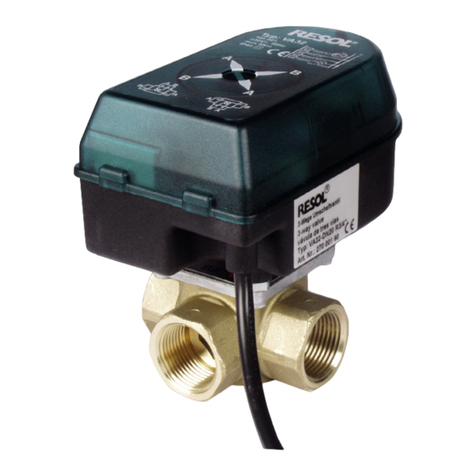
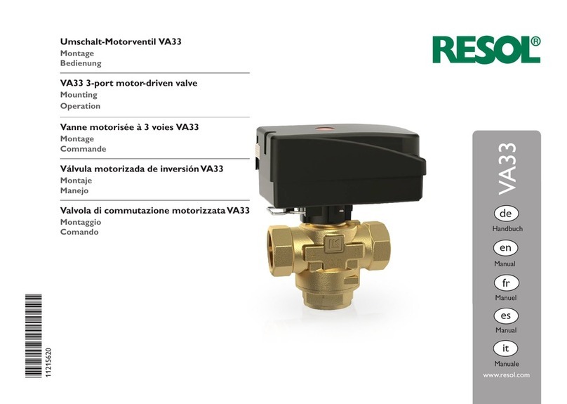
Resol VA32 User manual

*48004361*
48004361
Vielen Dank für den Kauf dieses RESOL-Gerätes.
Bitte lesen Sie diese Anleitung sorgfältig durch,um die Leistungsfähigkeit dieses Gerätes optimal
nutzen zu können. Bitte bewahren Sie diese Anleitung sorgfältig auf.
VA32
www.resol.com
Handbuch
de
Montage
Anschluss
Bedienung
Handbuch für den
Fachhandwerker
Manuel
fr
Manual
en
Manual
es
Manuale
it

2
Symbolerklärung
Signalwörter kennzeichnen die Schwere der Gefahr,
die auftritt, wenn sie nicht vermieden wird.
• WARNUNG bedeutet, dass Personenschäden,
unter Umständen auch lebensgefährlicheVerletzun-
gen auftreten können
• ACHTUNG bedeutet, dass Sachschäden auftreten
können
Angaben zum Gerät
BestimmungsgemäßeVerwendung
Das VA32 ist für Schaltprozesse innerhalb einer So-
lar- oder Heizungsanlage unter Berücksichtigung der
in dieser Anleitung angegebenen technischen Daten
bestimmt.
Die bestimmungswidrige Verwendung führt zum Aus-
schluss jeglicher Haftungsansprüche.
CE-Konformitätserklärung
Das Produkt entspricht den relevanten
Richtlinien und ist daher mit der CE-Kenn-
zeichnung versehen. Die Konformitätser-
klärung kann beim Hersteller angefordert
werden.
Hinweis
Hinweise sind mit einem Informationssymbol
gekennzeichnet.
Irrtum und technische Änderungen vorbehalten.
ÎTextabschnitte, die mit einem Pfeil gekennzeich-
net sind, fordern zu einer Handlung auf.
WARNUNG! Warnhinweise sind mit einem Warn-
dreieck gekennzeichnet!
ÎEs wird angegeben, wie die
Gefahr vermieden werden
kann!
Hinweis
Starke elektromagnetische Felder können
die Funktion des Reglers beeinträchtigen.
ÎSicherstellen,dass Regler und Anlage kei-
nen starken elektromagnetischen Strah-
lungsquellen ausgesetzt sind.
© 20130425_48004361_VA32.mon5s.indd
Sicherheitshinweise
Bitte beachten Sie diese Sicherheitshinweise genau,
um Gefahren und Schäden für Menschen und Sach-
werte auszuschließen.
Vorschriften
Beachten Sie bei allen Arbeiten die nationalen und
regionalen gesetzlichen Vorschriften, Normen, Richt-
linien und Sicherheitsbestimmungen.
Zielgruppe
Diese Anleitung richtet sich ausschließlich an autori-
sierte Fachkräfte.
Elektroarbeiten dürfen nur von Elektrofachkräften
durchgeführt werden.
Die erstmalige Inbetriebnahme hat durch den Erstel-
ler der Anlage oder einen von ihm benannten Fach-
kundigen zu erfolgen.
Entsorgung
• Verpackungsmaterial des Gerätes umweltgerecht
entsorgen.
• Altgeräte müssen durch eine autorisierte Stelle
umweltgerecht entsorgt werden.Auf Wunsch
nehmen wir Ihre bei uns gekauften Altgeräte
zurück und garantieren für eine umweltgerechte
Entsorgung.
Inhalt
1 Übersicht.................................................... 3
2 Installationshinweise ................................. 4
2.1 Einbaulage...................................................................4
3 Verschraubung........................................... 5
4 Betriebsart................................................. 5
5 Änderung der Durchflussrichtung........... 5
5.1 Automatikbetrieb.....................................................5
5.2 Handbetrieb...............................................................5
6 Ansteuerung 2-Punkt................................ 6
7 Anwendungsbeispiele................................ 7
8 Ersatzteile .................................................. 7

de
3
1 Übersicht
• Motor-Umschaltventil
• Keine Durchflussreduzierung
• Antriebseinheit ohneVentilausbau
auswechselbar
• Einfache Handverstellung
Technische Daten
Antrieb
Leistungsaufnahme:
Relais ein,Antrieb läuft: 9 VA
Relais ein,Antrieb steht: 5 VA
Relais aus: 0 VA
Schutzart: II (EN60335-1)
Antriebschutzklasse: IP 44 (IEC529)
Ausgangssignal: Phase L, 1 (1) A
Anschlussleitung: 4 x 0,5 mm², L = 1,0 m
Stellwinkel: 90 °
Stellzeit: 18 s/90 °
Drehmoment: 6 Nm (max. 8 Nm)
Umgebungstemperatur: 0 ... 55 °C
Betriebsart: offen – geschlossen
Ventil
Drehmoment: 6 Nm (max. 8 Nm)
Max.Arbeitstemperatur: 2 ... 110 °C
Max.Arbeitsdruck: 6 bar
Gehäuse: Schmiedemessing
Rotor mit Achse: Messing
Achsenabdichtung: 4 x O-Ringe, EPDM
Möglichkeit der Motorsteuerung: UV-3
Zur Reduzierung der Axialreibung:
PA-Unterlegscheibe
Einsatzbereich:
Das Umschaltventil VA32 findet im Solar- und Hei-
zungsbereich seineVerwendung. Damit können einzel-
ne Anlagenteile zonenweise geschaltet werden, ferner
einzelneApparaturen bei Bedarf zu- oder abgeschaltet
werden.
Das Ventil verfügt über Handnotbetätigung, 1 integ-
riertes Relais zur Ansteuerung über ein 2-Punkt-Steu-
ersignal oder eine direkte Ansteuerung über einen
potenzialfreien Umschaltkontakt.
Leistungsmerkmale:
Kompakte Ausführung, gefällige Form und modernes
Design, schutzisoliertes Antriebsgehäuse. Einfache
manuelle Handverstellung für Inbetriebnahme oder
Notbetrieb. Elektrischer universeller Anschluss durch
integriertes Relais.
Der Endschalter-Signalausgang in Ventilstellung kann
für Steuerzwecke verwendet werden (max 1 A).
Schnelles Wechseln der Antriebseinheit ohne Ausbau
des Ventils möglich. Keine Durchflussreduzierung, vol-
ler Durchgang entsprechend der jeweiligen Ausfüh-
rung von DN20-DN32.
Abmessungen
DN 20 25 32
A ¾" 1" 1 ¼"
B 72 90 90
C 17,5 20,8 25,5
D 130,5 133,8 138
E 54 69 70,5

de
4
Teile desVentils
Nr. Bezeichnung Material Anzahl
1 Gehäuse CW617N 1
2 Schraube M5X10 DIN965 Zn Stahl 4
3 Drehschieber CW617N 1
4O-Ring
8,73 × 1,78 FKM grün 1
5O-Ring
11,6 × 2,4 EPDM 2
6O-Ring 23,3 × 2,4 EPDM 1
7O-Ring 27 × 2,5 EPDM 1
8 Anzeigeschild EL Zink 1
9 Ventildeckel GD-ZN Al4 Cu1 1
10 Tragdistanzhalter M6x15,7 Zn Stahl 2
11 Schraube
2,9 × 6,5
DIN 7981
Zn Stahl 2
12 Einsatz PPS 1
2 Installationshinweise
Die Montage des Ventils ist nach den einschlägigen
Regeln der Technik vorzunehmen. Dichtmittel- bzw.
Hanfreste oder dergleichen, dürfen nicht in den Ven-
tilkörper gelangen. Um eine Blockierung desVentiltel-
lers zu vermeiden, folgende Hinweise beachten und
jegliche Löt- oder Schweißarbeiten in direkter Umge-
bung desVentils vermeiden.
Hinweis
Um die optimale Betriebssicherheit zu errei-
chen, wird empfohlen die Anlage vorher zu
spülen und einen entsprechenden Schmutz-
fänger (0,65 µm) vor jedemVentil (s. Installa-
tionsschema) einzubauen.
2.1 Einbaulage
DasVentil ist beliebig einbaubar, jedoch nicht mit dem
Antrieb nach unten. Zur Bedienung der manuellen
Handverstellung +/- 90°, beim Elektroanschluss eine
Kabelschlaufe von ca. 25 cm vorsehen. Um für Servi-
cearbeiten genügend Arbeitsraum zu erhalten, einen
Wand- bzw. Geräteabstand von mind. 100 mm ein-
halten.
Montage und DemontageVentil / Antrieb

de
5
3 Verschraubung
Der Antrieb kann bei Bedarf mit dem Ventil ver-
schraubt werden. Dazu folgendermaßen vorgehen:
Den Schutzstift entfernen (1)
Mit einem Schraubendreher die vormontierte Schrau-
be festziehen (2)
Die Öffnung wieder mit dem Schutzstift verschließen (3)
Verschraubung des Antriebs mit dem Ventil
4 Betriebsart
Für Kontroll- und Servicearbeiten kann die Betriebs-
art des Ventils manuell eingestellt werden.
Im Handbetrieb wird der Stellantrieb nicht vom Steu-
ersignal beeinflusst, der Einstellhebel ist stufenlos ver-
stellbar.
Um die Betriebsart des Ventils umzustellen, wie folgt
vorgehen:
ÎMit einem Schraubendreher die Einstellschraube
um 90° drehen
Stellung AUTO : Automatikbetrieb
Stellung MAN : Handbetrieb
Hinweis
Nach Abschluss der Kontroll- und Service-
arbeiten muss die Betriebsart wieder auf
AUTO gestellt werden. Ein normaler Regel-
betrieb ist im Handbetrieb nicht möglich.
5 Änderung der Durchflussrichtung
Die Durchflussrichtung kann manuell verändert werden.
5.1 Automatikbetrieb
Eine Änderung der Durchflussrichtung im Automatik-
betrieb ist nur in der Relais-Ruhestellung möglich!
b
Druckverlustkennlinien
Zum Ändern der Durchflussrichtung A<>AB zu
AB<>B folgendermaßen vorgehen:
ÎDen Kopf der Einstellschraube herunterdrücken
und gedrückt halten
ÎDen Einstellhebel um 90° drehen, bis er einrastet
ÎDen Kopf der Einstellschraube loslassen
ÎFunktionskontrolle vornehmen (z.B.über den Regler-
Handbetrieb)
5.2 Handbetrieb
Im Handbetrieb ist der Einstellhebel stufenlos verstellbar.
Änderung der Durchflussrichtung

de
6
Regler
Schaltkontakt
Ader
Schwarz Steuerphase
Liegt der Schaltkontakt L (230 V~) vom
Regler an, so öffnet der Weg AB<>B.
Liegt kein Schaltkontakt vom Regler an,
wird dasVentil wieder in Ausgangslage zu-
rückgestellt AB<>A
Braun Dauerphase L (230V~)
Blau Neutralleiter N (230V~)
Rot Endschalter-Ausgangssignal (230 V~)
6 Ansteuerung 2-Punkt
WARNUNG! Elektrischer Schlag!
Die rote Endlageschalter-Ader ist
abisoliert und führt bei geöffneter
Ventilstellung Spannung!
ÎBetriebsspannung mit
externerVorsicherung max.
2 A absichern! Pumpe AUS
Pumpe EIN
Pumpe AUS
Pumpe EIN
1 Schwarz
2 Blau
3 Braun
4 Rot
1 Schwarz
2 Blau
3 Braun
4 Rot

de
7
7 Anwendungsbeispiele
Solarsystem mit 2 Kollektoren und 2 Speicher mit
3-Wege-Ventil zur Umschaltung der Speicherschicht-
beladung.
Solarsystem mit 1 Kollektor und 1 Speicher mit 3-Wege-
Ventil zur Umschaltung der Speicherschichtbeladung.
Notizen
8 Ersatzteile
VA32-Reparaturset Art.-Nr.: 112 011 83

Ihr Fachhändler: RESOL– Elektronische Regelungen GmbH
Heiskampstraße 10
45527 Hattingen/ Germany
Tel.: +49 (0)2324/96 48- 0
Fax: +49(0) 2324 /96 48-755
www.resol.de
Wichtiger Hinweis
Die Texte und Zeichnungen dieser Anleitung entstanden mit größtmöglicher Sorg-
falt und nach bestem Wissen. Da Fehler nie auszuschließen sind, möchten wir auf
folgendes hinweisen:
Grundlage Ihrer Projekte sollten ausschließlich eigene Berechnungen und Planun-
gen an Hand der jeweiligen gültigen Normen und Vorschriften sein.Wir schließen
jegliche Gewähr für die Vollständigkeit aller in dieser Anleitung veröffentlichten
Zeichnungen und Texte aus, sie haben lediglich Beispielcharakter. Werden darin
vermittelte Inhalte benutzt oder angewendet, so geschieht dies ausdrücklich auf
das eigene Risiko des jeweiligen Anwenders. Eine Haftung des Herausgebers für
unsachgemäße, unvollständige oder falsche Angaben und alle daraus eventuell ent-
stehenden Schäden wird grundsätzlich ausgeschlossen.
Anmerkungen
Das Design und die Spezifikationen können ohneVorankündigung geändert werden.
Die Abbildungen können sich geringfügig vom Produktionsmodell unterscheiden.
Impressum
Diese Montage- und Bedienungsanleitung einschließlich aller seiner Teile ist urhe-
berrechtlich geschützt. Eine Verwendung außerhalb des Urheberrechts bedarf der
Zustimmung der Firma RESOL–Elektronische Regelungen GmbH. Dies gilt
insbesondere für Vervielfältigungen/ Kopien, Übersetzungen, Mikroverfilmungen
und die Einspeicherung in elektronischen Systemen.
Herausgeber: RESOL–Elektronische Regelungen GmbH

VA32
www.resol.de
Mounting
Connection
Operation
Manual for the
specialised craftsman
www.resol.com
Manual
en
Thank you for buying this RESOL product.
Please read this manual carefully to get the best performance from this unit. Please keep this manual carefully.

en
10
Description of symbols
WARNING! Warnings are indicated with a war-
ning triangle!
ÎThey contain information
on how to avoid the danger
described.
Signal words describe the danger that may occur,
when it is not avoided.
• WARNING means that injury, possibly life-threa-
tening injury, can occur.
• ATTENTION means that damage to the appli-
ance can occur.
ÎArrows indicate instruction steps that should be
carried out.
Target group
These instructions are exclusively addressed to au-
thorised skilled personnel.
Only qualified electricians should carry out electrical
works.
Initial installation must be effected by qualified per-
sonnel named by the manufacturer.
Safety advice
Please pay attention to the following safety advice
in order to avoid danger and damage to people and
property.
Instructions
Attention must be paid to the valid local standards,
regulations and directives!
Information about the product
Proper usage
TheVA32 is designed for switching processes in a so-
lar or heating systems in compliance with the techni-
cal data specified in this manual.
Improper use excludes all liability claims.
Note
Notes are indicated with an information
symbol.
Note
Strong electromagnetic fields can impair the
function of the controller.
ÎMake sure the controller as well as the
system are not exposed to strong elec-
tromagnetic fields. Disposal
• Dispose of the packaging in an environmentally
sound manner.
• Dispose of old appliances in an environmentally
sound manner. Upon request we will take back
your old appliances bought from us and guarantee
an environmentally sound disposal of the devices.
© 20130425_48004361_VA32.mon5s.indd
Contents
1 Overview .................................................. 11
2 Installation ............................................... 12
2.1 Mounting position ..................................................12
3 Mounting the actuator............................ 13
4 Operating mode ..................................... 13
5 Changing the flow direction ................... 13
5.1 Automatic mode.....................................................13
5.2 Manual mode...........................................................13
6 On-Off control ......................................... 14
7 Examples.................................................. 15
8 Spare parts............................................... 15
CE-Declaration of conformity
The product complies with the relevant di-
rectives and is therefore labelled with the CE
mark.The Declaration of Conformity is availa-
ble upon request, please contact RESOL.
Subject to technical change. Errors excepted.

en
11
1 Overview
• Motor-driven 3-port diverter valve
• No flow reduction
• Actuator can be replaced without disassem-
bling the valve
• Easy manual operation
Technical data
Actuator
Power consumption:
Relay on, motor running: 9VA
Relay on, motor in standby: 5 VA
Relay off: 0VA
Protection class: II (EN60335-1)
Ingress protection: IP 44 (IEc529)
Output signal: phase L, 1 (1) A
Connection line: 4 x 0.5 mm², L = 1 m
Regulating angle: 90°
Actuation time: 18 s /90°
Torque: 6 Nm (max. 8 Nm)
Ambient temperature: 0 ... 55 °C
Operation mode: open - closed
Valve
Torque: 6 Nm (max. 8 Nm)
Max. operating temperature: 2 ... 110 °C
Max. operating pressure: 6 bar
Housing: forged brass
Rotor with the axle: brass
Axle sealing: 4 x O-rings, EPDM
Possibility of motor control: UV-3
For reduction of axle friction: PA-plate
Application area:
The motor-driven 3-port valve VA32 is used in solar
and heating systems, in which smaller parts of the sys-
tems can be controlled separately or single equipment
can be switched on or off.
The valve is equipped with an emergency manual con-
trol, an integrated relay which can be controlled via
an on-off control signal or directly via a potential-free
changeover contact.
Characteristics:
Compact size and modern design, insulated actuator
housing. Easy manual operation for initial installation
or emergency operation. Universal electrical connec-
tion by integrated relay.
The signal output of the limit switch in valve position
can be used for control purposes (max. 1 A).The posi-
tion of the ball valve is visible with the white indicator
flag.The actuator can be quickly replaced without di-
sassembling the valve.The DN20 and DN32 versions
offer full bore flow.
Dimensions
DN 20 25 32
A ¾" 1" 1 ¼"
B 72 90 90
C 17,5 20,8 25,5
D 130,5 133,8 138
E 54 69 70,5

en
12
Components 2 Installation
The installation of the valve must be carried out cor-
responding to the approved technical regulations. En-
sure excess sealing material, tape etc does not enter
the valve body. In order to avoid blocking of the valve
ball, the following advice has to be considered and all
solder, brazing or welding processes near the valve
are to be avoided.
Important note
In order to attain the maximum operating
safety and reliability, it is recommended to
flush the system and to insert an appropriate
strainer (0,65 µm) in front of each valve (see
installation scheme).
2.1 Mounting position
The valve can be mounted in any position, but not
with the actuator to the bottom. In order to use the
manual operation +/- 90°, a cable loop of approx.
25 cm has to be arranged during the electrical con-
nection. In order to have enough space to carry out
maintenance work,keep a distance of at least 100 mm
from the wall or the device respectively.
Mounting and demounting of valve and actuator
No Designation Material Quantity
1 Housing CW617N 1
2 Screw M5X10 DIN965 Zn steel 4
3 Valve flap CW617N 1
4O ring
8,73 × 1,78 FKM green 1
5O ring
11,6 × 2,4 EPDM 2
6O ring 23,3 × 2,4 EPDM 1
7O ring 27 × 2,5 EPDM 1
8 Indicator plate EL zinc 1
9 Plate GD-ZN Al4 Cu1 1
10 Distance piece M6x15,7 Zn steel 2
11 Screw
2,9 × 6,5
DIN 7981
Zn steel 2
12 Insert PPS 1

en
13
3 Mounting the actuator
The actuator can be attached to the valve. Please car-
ry out the following steps:
Remove the protection cap (1)
Tighten the pre-assembled srew using a screwdriver (2)
Place the protective cap onto the opening (3)
Mounting the actuator to the valve
4 Operating mode
For control and service work, the operating mode of
the valve can be manually adjusted.
In manual mode, the control signal does not affect the
actuator, the adjustment lever is continuously adjus-
table.
In order to change the operating mode of the valve,
proceed as follows:
ÎTurn the adjustment screw by 90° using a screw-
driver
AUTO position: automatic mode
MAN position: manual mode
Note
Always adjust the operating mode back to
AUTO when the control and service work is
completed. Normal operation is not possible
in manual mode.
5 Changing the flow direction
The flow direction can be manually changed.
5.1 Automatic mode
Changing the flow direction in automatic mode is only
possible if the relay is in the rest position!
b
Pressure drop curves
KVS values for F3L rotodiv
For changing the flow direction from A<>AB to
AB<>B, proceed as follows:
ÎPress down the head of the adjustment screw and
keep it pressed
ÎTurn the adjustment lever by 90° until it locks
ÎRelease the head of the adjustment screw
ÎCarry out the function control (e. g.via the manu-
al mode of the controller)
5.2 Manual mode
In manual mode, the adjustment lever is continuously
adjustable.
Change of flow direction

en
14
brown
blue
black
red
control cont.
Ader
Black control line
if the auxiliary phase L (230 V~) is energi-
sed, the path AB<>B opens. If there is no
control signal, the valve is put back to the
initial position AB <> A
Brown permanent live L (230V~)
Blue neutral line N (230V~)
Red limit switch output signal
6 On-Off control
WARNING! Electric shock!
The red limit switch lead is not in-
sulated and carries voltage when
the valve is in the open position!
ÎFuse the operating voltage
with external pre-fuse max.
2A! Pump OFF
Pump ON
Pump OFF
Pump ON
1 black
2 blue
3 brown
4 red
1 black
2 blue
3 brown
4 red

en
15
7 Examples
Solar system with 2 collectors and two stores with
3-port valve for store loading in layers.
Solar system with 1 collector and 1 store with 3-port
valve for store loading in layers.
Note
8 Spare parts
VA32 repair kit Article no.: 112 011 83

Distributed by: RESOL – Elektronische Regelungen GmbH
Heiskampstraße 10
45527 Hattingen/ Germany
Tel.: +49 (0)2324/96 48- 0
Fax: +49(0) 2324 /96 48-755
www.resol.com
Important note
We took a lot of care with the texts and drawings of this manual and to the best of
our knowledge and consent.As faults can never be excluded, please note:
Your own calculations and plans, under consideration of the current standards and
directions should only be basis for your projects.We do not offer a guarantee for
the completeness of the drawings and texts of this manual - they only represent
some examples.They can only be used at your own risk. No liability is assumed for
incorrect, incomplete or false information and / or the resulting damages.
Note
The design and the specifications can be changed without notice.
The illustrations may differ from the original product.
Imprint
This mounting- and operation manual including all parts is copyrighted. Another
use outside the copyright requires the approval of RESOL – Elektronische Rege-
lungen GmbH.This especially applies for copies, translations, micro films and the
storage into electronic systems.
Editor: RESOL – Elektronische Regelungen GmbH

VA32
www.resol.de
Montage
Raccordement
Commande
Manuel pour
le technicien habilité
Merci d'avoir acheté ce produit RESOL.
Veuillez lire le présent mode d’emploi attentivement afin de pouvoir utiliser l’appareil de manière optimale.
Veuillez conserver ce mode d’emploi. www.resol.fr
Manuel
fr

fr
18
© 20130425_48004361_VA32.mon5s.indd
Informations concernant l’appareil
Utilisation conforme
La vanne d‘inversion VA32 s‘utilise dans le domaine
du chauffage solaire et du chauffage conventionnel
en tenant compte des données techniques énoncées
dans le présent mode d’emploi.Toute utilisation non
conforme aux prescriptions du fabricant exonérera
celui-ci de toute responsabilité.
Recommandations de sécurité
Veuillez lire attentivement les recommandations de
sécurité suivantes afin d‘éviter tout dommage aux
personnes et aux biens.
Instructions
Lors des travaux, veuillez respecter les normes, régle-
mentations et directives en vigueur!
Déclaration de conformité CE
Le marquage „CE“ est apposé sur le produ-
it, celui-ci étant conforme aux dispositions
communautaires prévoyant son apposition.
La déclaration de conformité est disponible
auprès du fabricant sur demande.
Note
Des champs électromagnétiques trop élevés
peuvent perturber le fonctionnement de
l‘appareil.
ÎVeillez à ne pas exposer ce dernier à des
champs électromagnétiques trop élevés.
Sommaire
1 Vue d´ensemble ....................................... 19
2 Indications pour l‘installation................. 20
2.1 Position de montage..............................................20
3 Raccordement ......................................... 21
4 Mode de fonctionnement ....................... 21
5 Changement de sens du courant........... 21
5.1 Mode automatique.................................................21
5.2 Mode manuel...........................................................21
6 Commande tout ou rien......................... 22
7 Exemples d‘application ........................... 23
8 Pièces de rechange.................................. 23
Groupe cible
Ce manuel d‘instructions vise exclusivement les tech-
niciens habilités.
Toute opération électrotechnique doit être effectuée
par un technicien en électrotechnique.
La première mise en service de l‘appareil doit être
effectuée par le fabricant ou par un technicien désigné
par celui-ci.
Explication des symboles
AVERTISSEMENT ! Les avertissements de sécurité
sont précédés d’un triangle de
signalisation !
ÎIl est indiqué comment
éviter le danger !
Les avertissements caractérisent la gravité du danger
qui survient si celui-ci n’est pas évité.
• Avertissement indique que de graves dommages
corporels, voire même un danger de mort peuvent
survenir.
• Attention indique que des dommages aux biens
peuvent survenir.
ÎLes instructions sont précédées d‘une flèche
Traitement des déchets
• Veuillez recycler l‘emballage de l‘appareil.
• Les appareils en fin de vie doivent être dépo-
sés auprès d‘une déchèterie ou d‘une collecte
spéciale de déchets d‘équipements électriques et
électroniques. Sur demande, nous reprenons les
appareils usagés que vous avez achetés chez nous
et garantissons ainsi une élimination respectueuse
de l’environnement.
Sous réserve d’erreurs et de modifications
techniques
Note
Toute information importante communiquée
à l‘utilisateur est précédée de ce symbole.

fr
19
1 Vue d´ensemble
• Vanne motorisée à 3 voies
• Pas de réduction de débit
• Possibilité de changer le moteur sans dé-
monter la vanne
• Réglage manuel simple
Caractérictiques techniques du moteur
Puissance absorbée:
relais activé, moteur en marche: 9Va
relais activé, moteur à l'arrêt: 5 Va
relais désactivé: 0Va
Type de protection: II (EN 60335-1)
Classe de protection: IP 44 (IEC529)
Signal de sortie: phase L, 1 (1) A
Câble de branchement: 4 x 0,5 mm², L = 1,0 m
Angle de réglage: 90 °
Durée d´actionnement: 18 s / 90 °
Couple: 6 Nm (max. 8 Nm)
Température ambiante: 0 ... 55 °C
Mode de fonctionnement: ouvert - fermé
Caractérictiques techniques de la vanne
Couple: 6 Nm (max. 8 Nm)
Température maximale de fonctionnement:
2 ... 110 °C
Pression maximale de fonctionnement: 6 bar
Corps de la vanne: en laiton forgé
Rotor axe: en laiton
Joints de l’axe: 4 x joint ronds, EPDM
Commande moteur: UV-3
Réduction du frottement axial: à travers
rondelle Pa
Champs d‘application :
La vanne d‘inversion VA32 s‘utilise dans le domaine
du chauffage solaire et du chauffage conventionnel.
Elle permet de mettre individuellement sous tension /
hors tension des zones précises de votre installation
solaire.
La vanne peut se régler manuellement en cas d‘urgence
et dispose d‘un relais intégré pour assurer la comman-
de d‘un signal tout ou rien et d‘un contact inverseur
sans potentiel permettant la commande directe de la
vanne.
Propriétés de laVA32 :
Modèle compact, forme séduisante et design mo-
derne; moteur doté d‘un boîtier protecteur isolant.
Réglage manuel pour la mise en marche ou l‘arrêt
d‘urgence. Branchement électrique universel à travers
un relais intégré.
Le signal de sortie de l‘interrupteur de fin de course
peut être utilisé pour manoeuvrer la vanne (maximum
1 A).Possibilité de changer le moteur rapidement sans
démonter la vanne. Il n‘est pas possible de régler le
degré d‘ouverture de la vanne, conformément aux
versions correspondantes DN20-DN32.
Dimensions
DN 20 25 32
A ¾" 1" 1 ¼"
B 72 90 90
C 17,5 20,8 25,5
D 130,5 133,8 138
E 54 69 70,5

fr
20
Composants de la vanne 2 Indications pour l‘installation
Le montage de la vanne doit s‘effectuer confor-
mément aux règles techniques locales. Veillez à ce
qu‘aucun reste de chanvre, de produit d‘étanchéité
etc... ne pénètre dans la vanne. Afin d‘empêcher la
vanne de se bloquer, lisez les indications suivantes et
éviter toute opération de soudage près de celle-ci.
Indication importante :
Afin d‘assurer le bon fonctionnement de la
vanne,il est conseillé de rincer l‘installation so-
laire et d‘installaler un séparateur d‘impuretés
(0,65 µm) devant toutes les vannes de votre
installation avant d‘installer laVA32 (voir sché-
ma d‘installation).
2.1 Position de montage
La vanne peut se monter dans n‘importe quelle posi-
tion, sauf avec le moteur vers le bas. Lors du branche-
ment électrique de la vanne, laissez 25 cm de câble en
plus afin de pouvoir régler celle-ci manuellement +/-
90°. Prévoyez également un écart d‘au moins 100 mm
entre le mur et l‘appareil afin d‘avoir assez de place
pour effectuer des opérations d‘entretien.
Montage et démontage vanne / moteur
No. Dénomination Matériau Quantité
1 Boîtier CW617N 1
2 Vis M5X10 DIN965 Zn acier 4
3 Clapet CW617N 1
4Joint rond
8,73 × 1,78 FKM vert 1
5Joint rond
11,6 × 2,4 EPDM 2
6Joint rond
23,3 × 2,4 EPDM 1
7Joint rond
27 × 2,5 EPDM 1
8Plaque indicatrice EL zinc 1
9 Couvercle GD-ZN Al4 Cu1 1
10 Pièce de distance M6x15,7 Zn acier 2
11 Vis 2,9 × 6,5 DIN 7981
Zn acier 2
12 Pièce PPS 1
Other manuals for VA32
1
Table of contents
Languages:
Other Resol Control Unit manuals