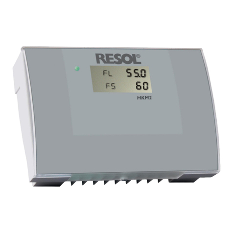
Resol HKM2 User manual

www.resol.de
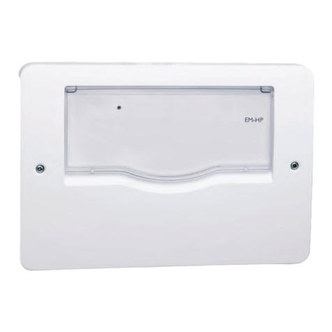
RESOL HKM2
Heating circuit module
HKM2
Thanks for buying.
Read this manual carefully to get the best perfomance from this unit.
Operation
Mounting
Electrical Connection
48003370
*48003370*
manual

© RESOL 07192 HMK2.monen.indd
HKM2
|2
Security instruction............................................................ 2
Application examples ........................................................ 4
1. Installation................................................................ 5
1.1 Wall mounting.............................................................................5
1.2 Electrical connection.................................................................5
1.3. Connecting terminals................................................................6
2. Sensor types ............................................................. 7
3. Function survey........................................................ 8
3.1 Heating circuit.............................................................................8
3.2 Timer ............................................................................................8
3.3 Remote control ..........................................................................8
3.4 Switch-off heating circuit..........................................................8
3.5 Rapid heating-up.........................................................................8
3.6 Feed flow set temperature ......................................................9
3.7 Mixer regulation .........................................................................9
3.8 Domestic water priority ..........................................................9
3.9 Blocking protection of the heating circuit pump ...............9
3.10 Anti-freeze function...................................................................9
3.11 Store after-heating .....................................................................9
4. Operation and Adjustment................................... 10
4.1 Control parameters................................................................ 10
4.1.1 Feed flow set temperature ................................................... 11
4.1.2 Ambient temperature ............................................................ 11
4.1.3 Remote contol correction .................................................... 11
4.1.4 Feed flow set temperature ................................................... 11
4.1.5 Store temperature .................................................................. 11
4.1.6 Nightly temperature lowering.............................................. 11
4.1.7 Daily correction....................................................................... 11
4.1.8 Maximum feed flow temperature........................................ 12
4.1.9 Heating curve........................................................................... 12
4.1.10 Mixer runtime.......................................................................... 12
4.1.11 Summer operation.................................................................. 12
4.1.12 Domestic water priority ....................................................... 12
4.1.13 Timer ......................................................................................... 12
4.1.14 HKM expert ............................................................................. 13
4.1.15 Manual operation .................................................................... 14
4.1.16 LED-Blinking codes................................................................. 14
5. Commissioning ......................................................14
6. Tips for fault localization ......................................14
6.1 Cause and solution ................................................................. 15
Contents
Security advice
Please pay attention to the following security advice in order
to avoid danger and damage to people and property.
Instructions
Attention should be paid
- to the statutory provisions for prevention of industrial
accidents,
- to the statutory provisions for environmental protection,
- to the Health and Safety at Work Act 1974
- to Part P of the Building Regulations 2005
- to BS7671 Requirements for electrical installations and
relevant safety regulations of DIN, EN, DVGW,TRGI,TRF
and VDE.
This instruction is exclusively addressed to authorised
skilled personnel.
- Only qualified electricians should carry out electrical
works.
- Initial installation should be effected by named qualified
personnel
Declaration of conformity
We, RESOL Elektronische Regelungen GmbH, D-45527
Hattingen, declare under our sole responsibility that our
product HKM2 complies with the following standards:
EN 55 014-1
EN 60 730-1
According to the regulations of the above directives, the
product is labelled with :
89/336/EWG
73/ 23/EWG
Hattingen, 07.07.2006
RESOL Elektronische Regelungen GmbH,
ppa. Gerald Neuse
© RESOL 07192 HMK2.monen.indd
HKM2
3 |
Accessory
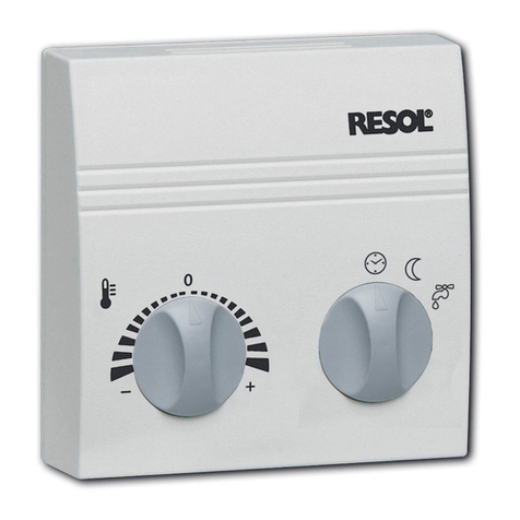
Remote controller RTA11-M
The remote controller RTA11-M serves for the adjustment of the heating curve of the
controller.An increase of the heating curve causes also an increase of the feed flow set
temperature, a lowering stands for a decrease of the feed flow set temperature. Further-
more, the remote controller comprises the function „Heating circuit off“ und „Rapid
heating up“.
Information concerning orders
RTA11-M remote controller Artikel-Nr.: 136 000 20
Information concerning orders:
Item number
• RESOL HKM2 145 440 30
Heating circuit module for a heating circuit controlled by atmospheric conditions
• RESOL HKM2 - complete package 145 440 40
Heating circuit module for a heating circuit controlled by atmospheric conditions
incl.Ambient temperature sensor FAP12 and Feed flow sensor FRP21
Can fuse
(T4A)
Fixing openening
Sensor terminals
Net terminals
LC- Display
Operating- LED
Cable entry points
Ground clamp
Electronic - cover
Cover locking screw
Programming plug
VBus- connection
115 V~
Relay terminals
Operating buttons
Manual switch

© RESOL 07192 HMK2.monen.indd
HKM2
|4
• Heating circuit (weather-controlled)
• Timer (weekly timer)
• Remote control
• Mixer regulation
• Domestic water priority
• Blocking protection of the heating circuit pump
• Anti-freeze function
• Weather-controlled store after-heating
RESOL systems can be extended into heating-/solar control-
ler units by means of the HKM2.
The heating circuit module disposes of :
6 sensor inputs (Pt1000)
5 relay outputs
Operating control lamp
Manual control switch
Technical data
Housing:
plastic, plug-in
Protection type
IP20 / DIN40050
Size:
208 x 141 x 65 mm
Ambient temperature:
0 ...40 °C
Inputs:
4 sensor inputs Pt1000
1 RTA11-M
Outputs:
4 standard relays
1 potential free change-over
contact
Display: LC-Display,
7-segmental-Display
Adjustment range:
-40 °C ...+250 °C
Supply:
115 V (AC), 50 ... 60 Hz
Total power supply:
4 A max.
Bus-Connection
RESOL VBus
Scope of delivery
1 x HKM2
1 x replacement fuse T4A
3 x Screws for Wall fittings
3 x Dowels for Wall fittings
Application examples
The pictogramms included in this manual show only some of the controller functions and do not qualify for being complete.They just illustrate a selection
of the possible applications.

© RESOL 07192 HMK2.monen.indd
HKM2
5 |
The electrical connection must be effected according to the
relative electric connection plan .
The HKM2 must be seperated from the power line via an
additional device with an all pole break line of at least 3 mm
or via a separator according to the valid installation regula-
tions.You can either use LS-contactors or fuses.
Electrical lines
The cable ducts at the wall housing are appropriate to fixed
and flexible lines with an external diameter of 5 mm up to
12 mm.
The lines are inserted from the bottom into the lead slots
and bent into the lead channels.The sheat insulation must
be removed approx. 5 cm from the clamps.All lines must be
fixed directly below the wall housing with strain reliefs on
the wall as prescribed.
Please pay attention to a separate laying of the sensor lines
when installing the mains feeder.
Warning!
Switch-off power supply before
opening the housing.
1.1 Wall mounting
1. Installation
The HKM2 has to be mounted on walls. Please pay attention
to the fact that the back of the wall housing is not accessible
when controller is mounted.The module in use has to be
protected from humidity, dirt and damage .The admissible
ambient temperature is from 0 up to 40 °C.
For opening the cover the fastening screw must be uns-
crewed by just one rotation . In this way the cover can be
flapped away.
Please fix the upper screw and hook the housing to the
upper hanging.The module can be straightened now, both
lower holes must be marked on the wall.After having remo-
ved the housing, the lower dowel holes can be drilled. For
the upper fixing of the housing, turn the appropriate dowel
just as far into the round head screw Ø4 x 35 mm so that
the housing can be just hooked- on. Now the housing can
be screwed by two more screws Ø 4 x 35 mm at the lower
part of the housing .
1.2 Electrical Connection

© RESOL 07192 HMK2.monen.indd
HKM2
|6
115 V~
VBus-connection
no function
1
2
3
4
5
6
7
8
9
10
11
12
13
14
15
16
Sensor feed flow
Sensor ambient
temperature
Sensor store sensor 1
Sensor store sensor 2
Remote control
(optional)
without function
17
18
19
20
21
22
23
24
25
26
27
28
29
30
Medium contact 5 *
Standard relay 3
Standard relay 2
Standard relay 1
Mains connection
1.3 Connecting terminals
The connection of the remote control can be effected by
terminals 3 and 4. The connection of the sensors can be
effected at the terminals 5 to 12 with a user-defined polarity
(see terminal scheme illustration 1).
The main controller and the HMK2 module are connected
via the RESOL VBus .The connection is effected by a user
defined polarity at terminals 13 and 14. The configuration
of the module is effected at the main controller. Activate
HK-Module with the menu of the main controller. From
DeltaSol
®M version 1.10 on, you can choose between
„No“, „HKM1“ und „HKM2“, in the previous versions bet-
ween „Yes“ and „No“,.All adjustments and display values are
listed in the corresponding menu (HK-module).
ill.1
no function
ill. 2
Changeover contact (ter-
minals 1-2) The connection of the consumers must be effected at the
terminals 1 to 12 in consideration of the polarity (Rx/N) (see
terminal scheme, ill 2).The ground wires are merged in the
ground wire collective terminal (illustration3).
* In the delivery condition terminals 3 and four are conn-
ceted via a jumper. The removal of the jumper results in a
potential-free relay for 115 V consumers at the terminals 1,
2 and 3 (break, work, common center).
The mains connection is to be effected at the terminals:
14 = neutral conductor N
13 = conductor L
ground wire - terminal block
R1 = HL-pump
R2 = Mixer ON
R3 = Mixer OFF
R4 = without function
R5 = After-heating
115 V~
115 V~
Take the ground wire-terminal block from the accessory bag.
Connect all ground wires in currentless state and insert it
into the deepinings of the terminal block (see position ill. 3).
ill. 3
ground wire-collector
terminal
In case that after-heating = Boiler (from DeltaSol
®M
1.10 on 2 store sensors can be used)
In case of an after-heating = Thermal- or after-heating =
boiler
Conductor L
1000 Ω
1360 Ω
1000 Ω
1000 Ω
Note:
The clamps (1-8) are factory-installed with 1000 ohms or
1360 ohms resistors. In case of an appropriate allocation of
the clamps, please remove the resistors.

© RESOL 07192 HMK2.monen.indd
HKM2
7 |
For the RESOL module HKM2 and the corresponding con-
troller precision temperature sensors in Pt1000 version
(FKP and FRP) are used
FK: Weather und temperature proof sillicone lines, 1,5 m
in length, for temperatures from -50 °C ...+180 °C, mostly
used for the collector.
2. Sensor types
Immersion sleeve: Deliverable for different lengths (im-
mersion depth)
FK...60: 60 mm immersion depth, brass sleeve, chromed
FK...150: 150 mm immersion depth, sleeve made of copper,
chromed
Important notice: Please push the sensor entirely into the
sleeve and tighten the screwing slightly.
Cylindrical clip-on sensors: for optional tube diameter,
completed with strain relief
FK...21 or FR...21
The sensor has to be in a good contact with the conduit.
Therefore please clean the contact surface thoroughly und
lay on a heat conducting paste between sensor and tube .In
order to protect it against ambient temperature influences
please wind the sensor lines once around the tube and
insulate it properly.
Flatscrew sensors: For installation on flat surfaces
FK...9 oder FR...9
Please pay attention to a good thermal contact.. Use a heat
conducting paste and an insulation against ambient tempe-
rature influences.
FR: PVC cable, 2,5 m in length, for tempertures between
-50 °C ...+80 °C, mostly used for stores.
Make sure that all electrical works are carried out accor-
ding to the relevant local and VDE-regulations.The sensor
cables carry low voltages and they must not run together
in a cable conduit with cables carrying higher voltages than
50Volts.When using longer cables or cable conduits, please
use shielded cables.The sensor cables can be extended up
to 100 m, but the cross-section of the extended cable must
be 1,5 mm² (or 0,75 mm² up to a cable length of 50 m); For
longer conduits and for a use in cable conduits, cables with
twisted conductors should be used preferably.The sensors
must not be in direct contact with water, please always use
immersion sleeves.

© RESOL 07192 HMK2.monen.indd
HKM2
|8
3.5 Heating circuit rapid heating-up A rapid heating-up of the heating circuit can only be realised
if the remote control is set to position „rapid heating pro-
cess“.
Rapid heating-up means that the mixer is fully started-up and
the heating circuit pump is switched-on.There is no regula-
tion of the feed flow temperature.The heating circuit rapid
heating-up should only be activated if the maximum feed
flow temperature exceeds the current store temperature.
The heating circuit will be switched-off if the maxiumum
feed flow temperature is reached.
3.1 Heating circuit (weather controlled): The feed flow set temperaure for the heating circuit results
from the ambient temperature and the chosen heating
curves.This feed flow set temperature can also be changed
with a remote control and the parameters „daily correc-
tion/nightly temperature lowering“. The control adjusts
the current heating circuit feed flow temperature to the
determined feed flow set temperature by opening/closing
the heat circuit mixer.
3.2 Timer (day programme):
The timer determines whether the daily correction or the
nightly temperature lowering is used for changing the feed
flow set temperature. If one of the time frames of the ti-
mer is „active“, the nightly temperature lowering is used. If
none of the time frames is active, the feed flow set value is
changed due to the daily correction.A time frame is „active“
when the current time is between the switch-on and the
switch-off time.
3.3 Remote controller: The remote control enables a parallel translation of the hea-
ting curve line (+/-15 K). Moreover, the heating circuit can be
switched- off or a rapid heating process can be started with
the remote control.The remote control is optional and not
contained in the full kit.
3.4 Switch-off heating circuit: The heating circuit can be switched-off manually if.
•the remote control is set to “Heatlp. off”
The heating circuit is switched-off automatically if
•the adjusted maximum feed flow temperature is reached
•the ambient temperature is higher than the adjusted sum-
mer temperature.
•the feed flow set temperature sensor is faulty.
•or the heating circuit at the controller is deactivated (per-
manently off)
Heating circuit switched-off means that the heat circuit pump
is switched-off and the mixer is shut down.
3. Function survey All settings for the HKM2 have to be adjusted with
the corresponding menu of the connected con-
troller! Please read the mounting instruction for
the controller in order to use all functions for the
HKM2.

© RESOL 07192 HMK2.monen.indd
HKM2
9 |
3.6 Feed flow set temperature: The feed flow set temperature results from the measured
ambient temperature and the chosen heating curve line.The
correction value of the remote control as well as the daily
correction or nightly temperature lowering are added to
these values.The feed flow set temperature = heating curve
line temperature + remote control + (daily correction or
nightly temperature lowering). If the calculated feed flow set
temperature is higher than the adjusted maximum feed flow
temperature, the feed flow set temperature is equated with
the maximum feed flow temperature.
3.7 Mixer regulation: The mixer regulation is used for aligning the feed flow
temperature with the feed flow set temperature. For this
purpose the mixer is started up/shut down according to
the deviation.The mixer is activated for the runtime of 4
seconds (factory setting).The pause is calculated from the
set and actual value.
3.8 Priority of domestic hot water This function switches-off the heating circuit during dome-
stic hot water after-heating. For this purpose the option do-
mestic hot water priority has to be activated and the after-
heating has to be effected by the boiler charge control.
3.9 Blocking protection for heating circuit pumps: The heating circuit pump is switched on every day at 12
o’clock for 30 seconds to avoid a getting stuck. of the
pump.This function doesn’t work if the feed flow set value
is reached, the feed flow sensor is damaged or the function
domestic water priority is activated.
3.10 Anti-freeze function If the temperature at the feed flow sensor falls below 8°C,
the heating circuit is switched-on. If the feed flow tempera-
ture reaches 10°C, the heating circuit is switched-off again.
3.11 Store after-heating (Differential controller): In order to start up the after-heating (abbr.: AH) of the
heating circuit, the difference between the calculated feed
flow set temperature and one (AH= thermal) or two store
sensors (AH=boiler) is measured. If the difference between
both temperatures is too low, the after-heating is activated.
The after heating is switched-off if the difference between
store and feed flow set temperature is high enough.

© RESOL 07192 HMK2.monen.indd
HKM2
|10
4. Operation and adjustment
Connect the HKM2 module via the RESOLVBus to the main
controller. Activate the HK-Module with the correspon-
ding menu option. From the DeltaSol
®M version 1.10 on
you can choose between „No“,„HKM1“ and „HKM2“, in the
previous versions between „Yes“ and „No“,.All parameters
are shown on the corresponding menu (HK-Module).
4.1 Controller parameter and display channels
•EC Error Code
Error Code, display channel HKM2
0 = OK
1 = sensor fault
2 = Bus defect
•VC Version Compatibility
System recognition of the HKM2 by the controller
display channel HKM2
0 = Bus defect
1 = HKM1
3 = HKM2
•SA Sub Address
Subadress for operation of VBus
Adjustment channel HKM2
•MM ManualMode
State of the relays, only if manual control switch is set
to I
0= R1 on, R3 on, 1 = R1 on R2 on, 2= R1 on
•PG ProGramme
Hardware version
Display channel HKM2
•VN VersioN
Software version,
Display channel HKM2
•FL FLow
Current feed flow temperature,
Display channel controller
•FS Flow Set
Current feed flow set temperature,
Display channel controller
•OU OUtdoor
Current ambient temperature,
Display channel controller
•S1 Store temperature 1
Current temperature of store sensor 1,
Display channel controller
•S2 Store temperature 2
Current temperature of store sensor 2,
Display channel controller
•RA Remote A djustement
Adjustment of the remote control
Display channel controller
•S6 Sensor 6
Only measured value without function
Display channel controller
•R1 Relay1:Heatingcircuitpump
Current state of the relay heating circuit pump
Display channel controller
•R2 Relay2:Mixeron
Current state of the relay for starting up
the mixer, display channel controller
•R3 Relay3:Mixeroff
Current state of the relay for shutting down
the mixer, display channel controller
•R5 Relay5:After-heating
Current state of the relay after-heating,
display channel controller
Channels HKM2

© RESOL 07192 HMK2.monen.indd
HKM2
11 |
4.1.1 Temperature feed flow
The value temperature feed flow indicates the feed flow
temperature of the heating circuits.
System/ heating circuits / HK-module / TFlow
Display range: -30,0°C ... 200,0°C
4.1.5 Store temperature 1
System / heating circuit s/ HK-module /
TSt
Display range: -30,0°C ... 200,0°C
4.1.7 Nightly lowering
System / heating circuit / HK-module / nightly
low.
Adjustment range: -40 K ... 0 K
Factory setting: -4 K
4.1.8 Daily correction
System / Heating circuits / HK-module / Dail. Corr..
Adjustment range: -5 K ... 15 K
Factory setting: 5 K
4.1.2 Ambient Temperature The value ambient temperature indicates the weather-
controlled ambient temperature.
System / heating circuits / HK-module / T outd.
Display range : -30,0°C ... 200,0°C
4.1.4 Feed flow set temperature
System/ Heating circuits / HK-module / Feed flow.set
value
Display range: 20°C ... 100°C
4.1.3 Remote control correction
4.1.6 Store temperature 2
System / heating circuits / HK-modules /
TST2
Display range: -30,0°C ... 200,0°C
The remote control enables a parallel translation of the
heating curve line at max. ±15 K. Furthermore, the heating
circuit can be switched off by means of a remote control
and it can start up the rapid heating-up.The value „remote
control correction“ indicates the parallel translation of the
heating curve line in Kelvin.The adjustment of the value is
to be exclusively effected at the external remote control
RESOL RTA11-M which has to be activated from the Del-
taSol
®M Version 1.10 on in the heating circuit /expert
menu.
The value feed flow set temperature indicates the target
value of the feed flow temperature . The measured ambi-
ent temperature and the chosen heating curve line result
in the feed flow set temperature. The correction value of
the remote controller as well as the daily correction or
the nightly lowering are also added up to the feed flow set
temperature..
Feed flow set temperature = heating curve line+ remote
controller + (daily correction or nightly lowering).
The store temperature indicates the temperature of the
store. If the temperature at the store sensor (S3) underruns
the feed flow set temperature by 4 K (factory setting), the
after-heating (relay 5)will be switched on.
It will be switched off again, if the temperature at the sensor
S3 exceeds the feed flow set temperature by 14 K (factory
setting) .
This value won’t be displayed until the option AH=Boiler
won’t selected.The in point 4.1.5 specified switching con-
dition is valid for both store sensors.This option enables a
longer after-heating runtime.
Adjustment channel for the nightly lowering of the heating
circuit.. Up to 21 weekly timers - depending on the system
- in which the feed flow set temperature is lowered by
the chosen temperature difference can be used for nightly
lowering.
Adjustment channel for the daily correction of the heating
circuit.The daily correction is always active outside of the
three time frames of the nightly lowering.The feed flow set
temperature is increased or lowered by the chosen tempe-
rature difference.
System / Heating circuits / HK-module / manual-corr.
Display range: -15,0°K ... +15,0°K

© RESOL 07192 HMK2.monen.indd
HKM2
|12
4.1.13 Timer:
System / heating circuits / HK-Module / Timer
The timer determines whether the daily correction or the
nightly lowering is used for the adjustment of the feed flow
set temperature. 21 different time frames can be adjusted
for the nightly lowering of the heating circuit. If one of the
adjusted time frames of the timer is ‚active‘, the nightly lo-
wering is used , If none of the time frames is ‘active’, the feed
flow set temperature is equated with the daily correction.
A time frame is ‘active’, if the current time is between the
switch-on and switch-off point.
Hei zkenn linie
20
40
60
80
100
120
140
-20-15 -10-505101520
Auße ntemp e ratur
V o r l a u f t e m p e r a t u r
3, 0
2, 7
2, 4
2, 1
1, 8
1, 5
1, 2
0, 9
0, 6
0, 3
4.1.8 Feed flow maximum temperature
System / Heating cicuits / HK-module /
TFeed flow max.
Adjustment range: 10°C ... 100°C
Factory setting: 50°C
Adjustment channel for the maximum allowable feed flow
temperature of the heating circuit. If the maximum feed flow
temperature is exceeded the heating circuit is shut down
(the mixer is shut down as well as the pump is shut down
depending on the selected option).
4.1.10 Mixer runtime The mixer is started up and shut down in accordance to
the deviation of the current feed flow temperature from
the feed flow set temperature.The mixer is activated for 4
seconds in each case (factory setting).The pause is calcula-
ted from the deviation from the set- and actual value.This
parameter conforms the mixer regulation to the manipula-
ting time of the mixer in use.
4.1.11 Summer operation
System / Heating circuits/ HK-module / SUMMER
Adjustment range: 0 °C ... 40 °C
Factory setting: 20 °C
Adjustment channel for summer operation. If the ambient
temperature exceeds the set value, the heating circuit is
switched-off.
4.1.12 Domestic hot water priority
System / Heating circuit / HK-module / D.H.W.
priority
Adjustment range:Yes ... No
Factory setting: no
This function switches-off the heating circuit during hot
water-after-heating. For this purpose option domestic hot
water priority and option store charge controll have to be
activated at the main controller.
Example: If the nightly lowering shall start on Tuesday between 10 p.m.
and 6 a.m. and 3p.m. and 6p.m.., t1-on has to be set to Tue.. 10 p.m., t1-off
to Tue.6 a.m., t2-on to Tue 3 p.m. and t2-off to Tue 6 p.m...
If all time frames stop at 00:00 o’clock, the nightly lowering is deactivated,
the heating circuit is at daily work for 7 days, 24 h.
Adjustment range: Mo 0.00....Sun.,11:59p.m.
Factory setting:T. on, every day 05:00 a.m.
T OFF: every day,10:00 p.m.
Dependency of the feed flow temperature on the ambient
temperature and the chosen heating curve line (Adjustment
range: 0,3 ... 3,0, factory setting: 1,0)
4.1.9 Heating curve
Heating curve family
Vorlauftemperatur in °C
Ambient temperature in °C
Systems / Heating circuits / HK-module / Mixer
Adjustment range: 1 sec.... 20 sec.
Factory setting: 4 sec.

© RESOL 07192 HMK2.monen.indd
HKM2
13 |
∆TAH on
Switch-on temperature difference
After-heating (After-heating = therm. or boiler)
If the temperature at the store sensor (S1,AH=Thermo) or
at both store sensors (S1 und S2, AH=Boiler), as the case
may be, underruns the feed flow set temperature by the
value ∆TAH on, the after-heating (Relay 5) is switched on
4.1.14. HKM Expert
(from DeltaSol
®MSW-Version1.10on)
After-heating
System / Heating circuit / HK-module / HKM Expert
/ After-heating
Adjustment range: No therm., Boiler
Factory setting: None
Manual-Corr.
Remote Control
SYSTEM / HEATING CIRCUITS/ HK-MODULE / HKM Expert / MAN.-
CORR.
Adjustment range:Yes...No
Factory Setting: No
With the connection of a RTA11-M remote control,this one
here has to be activated (Adjustment: Yes).
∆TNH off
Switch-off temperature difference
(After-heating=therm. or boiler)
System / heating circuit / HK-
module / HKM Expert / ∆TNH off
Adjustment range: -15K... 50 K
Factory setting: 4 K
The after-heating switches off if the temperature at the
store sensor (S1, NH=Thermo) or both store sensors (S1
und S2, NH=Boiler) exceeds the feed flow set temperature
exceeds by the value ∆TNH off .
PUMP HCMAX
Performance of the heating circuit pump when ex-
ceeding the feed flow maxiumum temperature
SYSTEM/ HEATING CIRCUIT / HK-MODULE / HKM Expert / Pump
HKmax
Adjustment range: On...Off
Factory Setting: Off
If the maximum feed flow temperature is reached, the hea-
ting circuit pump is switched off with the adjusment OFF.
With the adjustment ON the heating circuit pump continues.
(Only the mixer will be shut down).
Here the weather-controlled store after-heating can be
activated. Select adjustment therm. (function refers to S1)
or boiler (function refers to S1 and S2).With the adjusment
NONE the function will be deactivated.
System / heating circuit / HK-module /
HKM Expert / ∆TNH on
Adjustment range: -15K... 50 K
Factory setting: 4 K

© RESOL 07192 HMK2.monen.indd
HKM2
|14
4.1.15 Manual operation
The heating circuit and the heating circuit pump can be
switched on or off manually with the manual control switch.
In order to operate the HKM module at full capacity the
manual control switch should be set to “Auto“. With the
help of parameter MM the relays can be switched in diffe-
rent states : MM0 = R1 on, R3 on, MM1 = R1 on, R2 on,
MM2 = R1 on
Adjustment range: 0,Auto, I
Factory setting:Auto
4.1.16 LED - Blinking Codes
Constantly green: OK
Blinking red: Error
Sensor fault
115 V~
6.Tips for fault localization
5. Commissioning Please connect the power supply at first.The HKM2 mo-
dule passes through an initialisation phase during which the
operating control lamp is blinking.
Afterwards the module switches to the normal mode and
indicates the feed flow temperature FL and the feed flow
set temperature FS.
If the heating circuit module doesn’t work faultlessly, please
check the following points:
1. Power supply
If the operating control lamp is off, please check the power
supply of the controller.
The HKM2 is protected by a one can fuse T4 A which is
accessible and can be replaced by opening the cover of
the housing (spare fuse is enclosed in one of the accessory
bags).
2. Manual control switch
For faultless use of the control of the HKM2 module the
manual control switch should be set to “Auto“.
3. Sensor faults
If there is a malfunction due to a sensor defect, it is signa-
lised by the operating control lamp flashing red and symbol
being displayed. An error code for the affected sensor
is shown on the display. For checking the 3rd temperature
sensor the pushbutton 1 must be pressed once.
Short-circuit: Short-circuit in the sensor conductor
with indication of the affected tempera-
ture sensor. Error code -888.8 for this
sensor is shown on the display.
Line break: Interruption of the sensor conductor
with indication of the affected tempe-
rature sensor. Error code 888.8 for this
sensor is shown on the display.
Clamped Pt1000-temperature sensors can be checked with
a resistance-measuring device.The measured temperatures
can be compared to the resistance values shown on the
table. opposite
Resistance values of
the Pt1000-sensors

© RESOL 07192 HMK2.monen.indd
HKM2
15 |
6. Tips for fault localization
Description of symptons Possible causes / Solution
Heater is constantly on
- Please check if function „rapid heating process“ at the
remote control is activated?
- Ambient temperature sensor is not accurately-positi-
oned or faulty? (see „sensor faults“)
- Temperature value for summer activity is set too high?
Heater is constantly off
- Please check if function „heating circuit off“ at the
remote control is activated?
- pump is set to „0“ at the HKM2 (0ff)?
- Feed flow sensor fault? (see „sensor faults“)
- Temperature value for summer activity is set too low?
Heater heats very slowly - Adjusted value for mixer runtime is too low?
In spite of heating pauses, it is
constantly too warm
- Please check the adjusted heating curve, lower it if
necessary.
- Feed flow maximum temperature is too high? Lower it
if necessary.
- Please check the position of the remote control, choo-
se a ‘lower’ position if necessary.
- Adjusted value for daily correction too high? Lower it if
neccessary.
In spite of an active heater, it is
constantly too cold
- Adjusted heating curve line too low?
Raise it if necessary.
- Feed flow maximum temperature is too low?
Raise it if necessary.
- Please check the settings of the remote control.
- Please check the adjusted time.
- Please check the adjustments of the time frames for the
nightly correction in order to prevent an unintended
temperature drop.

© RESOL 07192 HMK2.monen.indd
HKM2
|16
Notes
Distributed by:
Comments:
The design and the specifications can be changed without advance notice.
The illustrations can differ from the production model
RESOL-ElektronischeRegelungenGmbH
Heiskampstraße 10
D - 45527 Hattingen
Tel.: +49 (0) 23 24 / 96 48 - 0
Fax: +49 (0) 23 24 / 96 48 - 55
www.resol.de
info@resol.de
Other manuals for HKM2
1
Table of contents
Other Resol Control Unit manuals
Popular Control Unit manuals by other brands

GE
GE Masoneilan VariPak 28001 instruction manual

BFT
BFT CSB Xtreme (1.2) Installation and operation manual

Advantech
Advantech PCM-3531 Startup manual

Sistemes Electrònics Progrés s.a.
Sistemes Electrònics Progrés s.a. AGRONIC 4000 instruction manual

ABB
ABB ACH580-04 Quick installation guide

Toshiba
Toshiba IK-HD2C instruction manual