manuals.online logo
Brands
  1. Home
  2. •
  3. Brands
  4. •
  5. RIGHT ANGLE
  6. •
  7. Indoor Furnishing
  8. •
  9. RIGHT ANGLE NewHeights 4 LT Series User manual

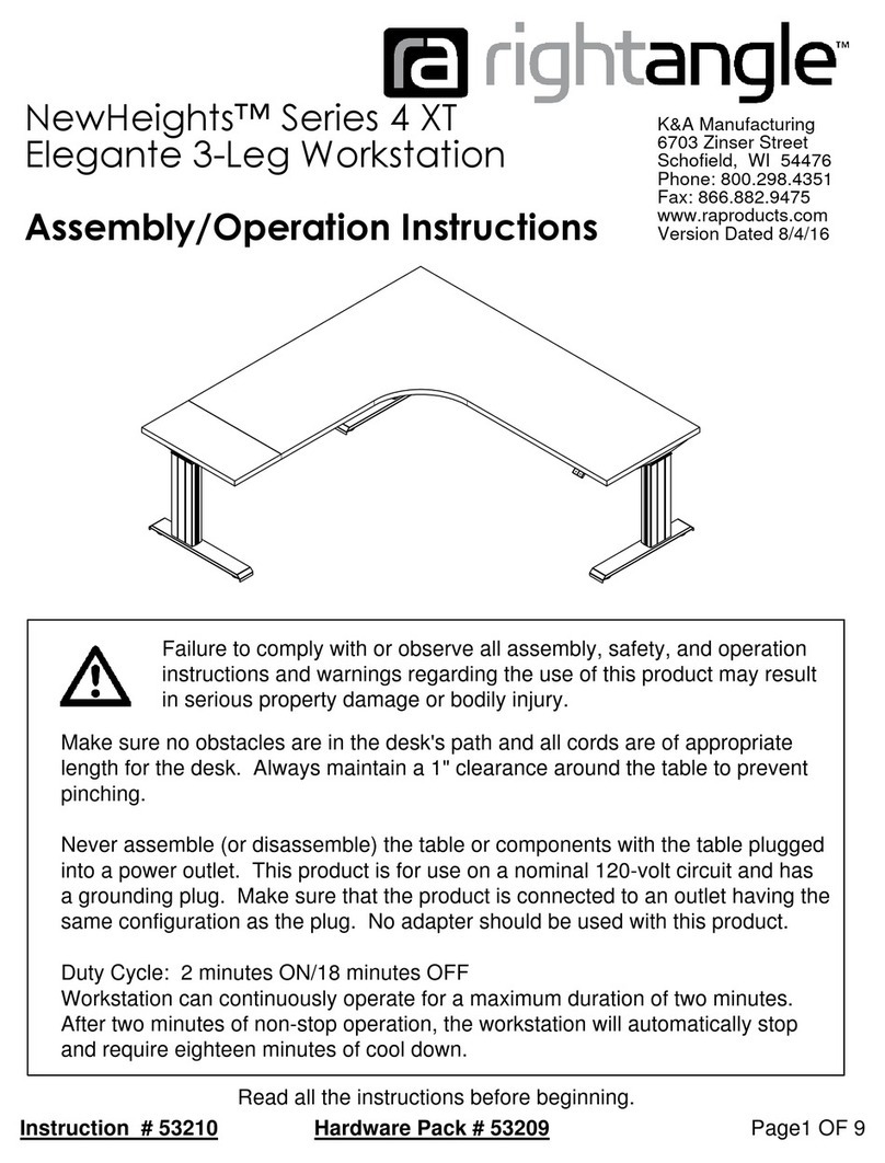
RIGHT ANGLE NewHeights 4 LT Series User manual

Page 1 OF 6Instruction # 53026 Hardware Pack # 53023
K&A Manufacturing
6703 Zinser Street
Schofield, WI 54476
Phone: 800.298.4351
Fax: 866.882.9475
www.raproducts.com
7/24/14
Read all the instructions before beginning.
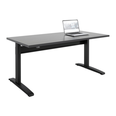
NewHeights Series 4 LT
Eficiente 2-Leg Workstation
53678
Page 2 OF 6
K&A Manufacturing
6703 Zinser Street Schofield, WI 54476
Phone: 800.298.4351
Fax: 866.882.9475
www.raproducts.com
Hardware is Drawn Actual Size
Hardware Pack # 53023
53013
4
53055 53025 53024 51708
52604 52236
5 9
10
BC
14
11
1
52900
15
Tools Required for Assembly:
Power Driver W/Adjustable Torque
#2 Phillips Head Driver Bit
#2 Square Head Driver Bit
3/16" Hex Head Driver Bit or
Allen Wrench
Adjustable Wrench
Tape Measure
Level
Warranty Information: NewHeights™ products are warranted to be free of defects due
to manufacturing or materials as follows: 2 years on the gear and/or motor including the
control box and switch. 5 years on the support brackets, aluminum columns, and feet.
We will replace any defective part after inspection by an authorized agent. Costs incurred
due to product replacement such as installation labor or transportation are not covered
under this warranty. When corresponding with RightAngle™ products, record and provide
the model and serial numbers located on the control box.
Instruction # 53026
800934
3
2
1
The motor must
face the back of
the worksurface.
Back
A
Detail A
3
4
5
6
Worksurface
Support
Page 3 OF 6
K&A Manufacturing
6703 Zinser Street Schofield, WI 54476
Phone: 800.298.4351
Fax: 866.882.9475
www.raproducts.com
Steps 1-3
ITEM # PART # DESCRIPTION QTY
1 Varies LT Worksurface 1
2 Varies LT Leg Assembly Left 1
3 Varies LT Hex Rod Assembly 1
4 01064 LT Motor & Bracket Assembly 1
5 53013 Split Lock Washer 1/4" 2
6 53055 Socket Head Cap Screw 1/4-20 x 7/16 2
7 Varies LT Leg Assembly Right 1
Varies Series 4 Cross Support 1
9 53025 5/16 Lock Washer 4
10 53024 5/16-1 x 1/2 Button Head Socket Screw 4
11 00934 Cross Support End Cap 2
12 5170 M5 x 1 mm (7/ ") Sq/Ph/Wshr Head Wood Screw 2
13 Varies LT U-Channel 1
14 52990 LT Control Box 1
15 502 5 NewHeights Hand Switch 1
16 52900 6 x 3/4 Phillips Pan Head Sheet Metal Screw 2
17 59169 Wire Management J 1
1 52604 3/16" Cable Clamp 1
Step 1: Lay the worksurface 1on a protected
surface with the pilot holes facing up. There
are metal inserts installed in the worksurface.
These will not be used for this workstation.
Place the left leg assembly 2on the work-
surface aligning the holes in the worksurface
support with the pilot holes in the worksurface.
The hex drive hole must face the inside of the
workstation.
Step 2: Insert the longer end of the hex rod
assembly 3through the hex drive on the
motor assembly 4and into the hex drive near
the top of the leg assembly 2. You may need
to turn the hex rod clockwise slightly using an
adjustable wrench to align it with the hex drive.
Step 3: Place (2) lock washers 5on (2)
socket screws 6. Insert these through the
holes in the motor bracket 4and thread them
into the cage nuts pre-installed in the work-
surface support. Hand tighten. You will not be
able to fully tighten the screws until later in
Step 10.
Instruction # 53026
3
Step 4
7
1
Pre-installed
Weld Nut
9
10
11
2
7
B
4.000
Page 4 OF 6
K&A Manufacturing
6703 Zinser Street Schofield, WI 54476
Phone: 800.298.4351
Fax: 866.882.9475
www.raproducts.com
Detail B
Detail C
Steps 5 & 6
Step 4: Place the right leg assembly 7on
the worksurface 1. Insert the end of the
hex rod 6into the hex drive on the right leg
assembly. You may need to turn the hex
rod clockwise slightly with an adjustable
wrench to align the hex rod with the hex
drive in the right leg assembly. It should
take no more than 1/6th of a turn to
accomplish this. If you turn it more than
1/6th of a turn, the legs will be at different
heights and the worksurface won't be level.
Align the holes in the worksurface support
with the pilot holes in the worksurface.
Step 5: With the help of an assistant, place
(4) lock washers 9on (4) socket screws 10 .
Insert these through the holes in the ends of
the cross support 8and thread them into
weld nuts that are pre-installed in the grooves
on the backs of the leg assemblies 2and 7.
See Detail B. Do not fully tighten. Level the
cross support at 4" from the bottom of the
worksurface support. See Detail C. Fully
tighten the socket screws.
Step 6: Insert (2) end caps 11 into the ends
of the cross support 8.
Instruction # 53026
12
14
17
12
13
12
1
12
16
15
12
12
7
2
1
if required by turning the
leveling glides clockwise
(from the top) on the low
corners of the workstation.
If your workstation has
casters, level it by turning
the bolts at the tops of the
casters.
Page 5 OF 6
K&A Manufacturing
6703 Zinser Street Schofield, WI 54476
Phone: 800.298.4351
Fax: 866.882.9475
www.raproducts.com
Step 7: Attach the leg assemblies 2and 7to the
worksurface 1using (16) wood screws 12 . Do not
over-tighten the screws. Use a low torque setting on the
power driver.
Step 8: Align the holes in the u-channel 13 with the
pilot holes in the worksurface 1. Attach it using (8) or
(10) wood screws 12 . Capture the switch wire in the
v-notch near the motor as shown below.
Step 9: Align the holes in the control box 14 with the
pilot holes in the worksurface 1. Attach it with (2)
wood screws 12 . Align the holes in the hand switch 15
with the pilot holes near the front of the worksurface.
Attach it with (2) sheet metal screws 17 . Capture the
switch wire in the clamp 18 and attach it with (1) wood
screw 12 in the location shown. No pilot hole is
provided. Attach the wire management J 17 to the
worksurface at the location shown below with (1) wood
screw 12 . No pilot hole is provided. Run the wires
from the switch and motor as shown below.
Step 10: Plug the power cord from the control box 14
into a standard 110v receptacle. A power surge
protector is recommended. Press both arrows on the
hand switch 15 . The control box will reset and beep
once. Press the down arrow on the hand switch until the
leg assemblies 2and 7bottom out and the control box
beeps (3) times. The workstation is now ready for use.
Raise the leg assemblies high enough to fully tighten the
motor assembly screws. Tighten the screws and return
the leg assemblies to their lowest position.
Step 11: With the help of an assistant, set the work-
station upright in its final position. Level the workstation
Critical procedure
that must be
performed at this
step and any time
the workstation
stops operating or
gets stuck in any
position. Damage
to the spindles
inside the leg
assemblies will
occur if this
procedure is not
followed.
Instruction # 53026
A
B
C
D
E
Page 6 OF 6
K&A Manufacturing
6703 Zinser Street Schofield, WI 54476
Phone: 800.298.4351
Fax: 866.882.9475
www.raproducts.com
Instructions To Install a Track on a Series 4 LT
Workstation:
Step 1: Place the front of the track Aagainst the
bottom of the worksurface and the back of the track
against the u-channel.
Step 2: Align the holes in the track Awith one set
of pilot holes in the u-channel Ekeeping the front
of the track 1/8"-5/8" from the front of the work-
surface. Place (2) washers Bon (2) self drilling
screws C. Drive them through the track and into
the u-channel.
Step 3: Attach the front of the track Ato the work-
surface using (2) wood screws D. Do not over-
tighten the screws. Use a low torque setting on the
power driver.
Step 4: Complete the installation using the
instructions that came with the product you are
installing.
ITEM # PART # DESCRIPTION QTY.
A Varies Track Assembly 1
B 52236 3/16" Aluminum Rivet Washer .19 x .510 x .067 2
C 5267 -1 X1/2 Phillips Pan Self Drill Screw 2
D 5170 M5 x 1 mm (7/ ") Sq/Ph/Wshr Head Wood Screw 2
E Varies LT U-channel 1
Reset Procedure and Troubleshooting: If the workstation stops operating or gets
stuck in any position, unplug and plug back in all the cord connections including the
power connection on the control box. Then repeat the startup procedure noted in
Step 10 on Page 4. The workstation should be ready for use.
If the workstation leg assemblies are at uneven heights, it is usually caused by an
improperly installed hex rod. Disassemble one of the legs from the worksurface and
make sure both ends of the hex rod are properly engaged in the hex drives near the
tops of the leg assemblies.
If you continue having problems with the table operation, contact RightAngle™
service at 800-298-4651 or orders@raproduts.com.
Instruction # 53026

Other RIGHT ANGLE Indoor Furnishing manuals
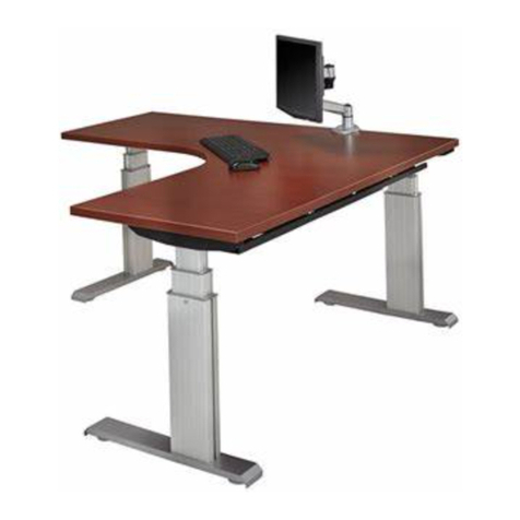
RIGHT ANGLE R-STYLE WORKSTATION 50643 User manual

RIGHT ANGLE

RIGHT ANGLE R-STYLE WORKSTATION 50643 User manual

RIGHT ANGLE R-Style Screw Height Adjustable User manual

RIGHT ANGLE

RIGHT ANGLE R-Style Screw Height Adjustable User manual

RIGHT ANGLE NewHeights Storage Bin User manual

RIGHT ANGLE

RIGHT ANGLE NewHeights Storage Bin User manual

RIGHT ANGLE NewHeights Electric Height Adjustable Conference... User manual

RIGHT ANGLE

RIGHT ANGLE NewHeights Electric Height Adjustable Conference... User manual

RIGHT ANGLE R-STYLE 36USL User manual

RIGHT ANGLE

RIGHT ANGLE R-STYLE 36USL User manual

RIGHT ANGLE 310CPU User manual

RIGHT ANGLE

RIGHT ANGLE 310CPU User manual

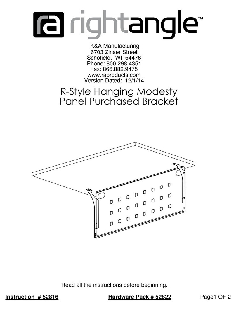
RIGHT ANGLE 4 Vuelta Series User manual
RIGHT ANGLE

RIGHT ANGLE 4 Vuelta Series User manual

RIGHT ANGLE NewHeights Presidente User manual

RIGHT ANGLE

RIGHT ANGLE NewHeights Presidente User manual

RIGHT ANGLE NewHeight 4 Series User manual

RIGHT ANGLE

RIGHT ANGLE NewHeight 4 Series User manual

RIGHT ANGLE R-Style Tango User manual

RIGHT ANGLE

RIGHT ANGLE R-Style Tango User manual

RIGHT ANGLE Hover Helium Junior User manual

RIGHT ANGLE

RIGHT ANGLE Hover Helium Junior User manual

RIGHT ANGLE NewHeights Gas Lift Adjustable SkateDesk User manual

RIGHT ANGLE

RIGHT ANGLE NewHeights Gas Lift Adjustable SkateDesk User manual

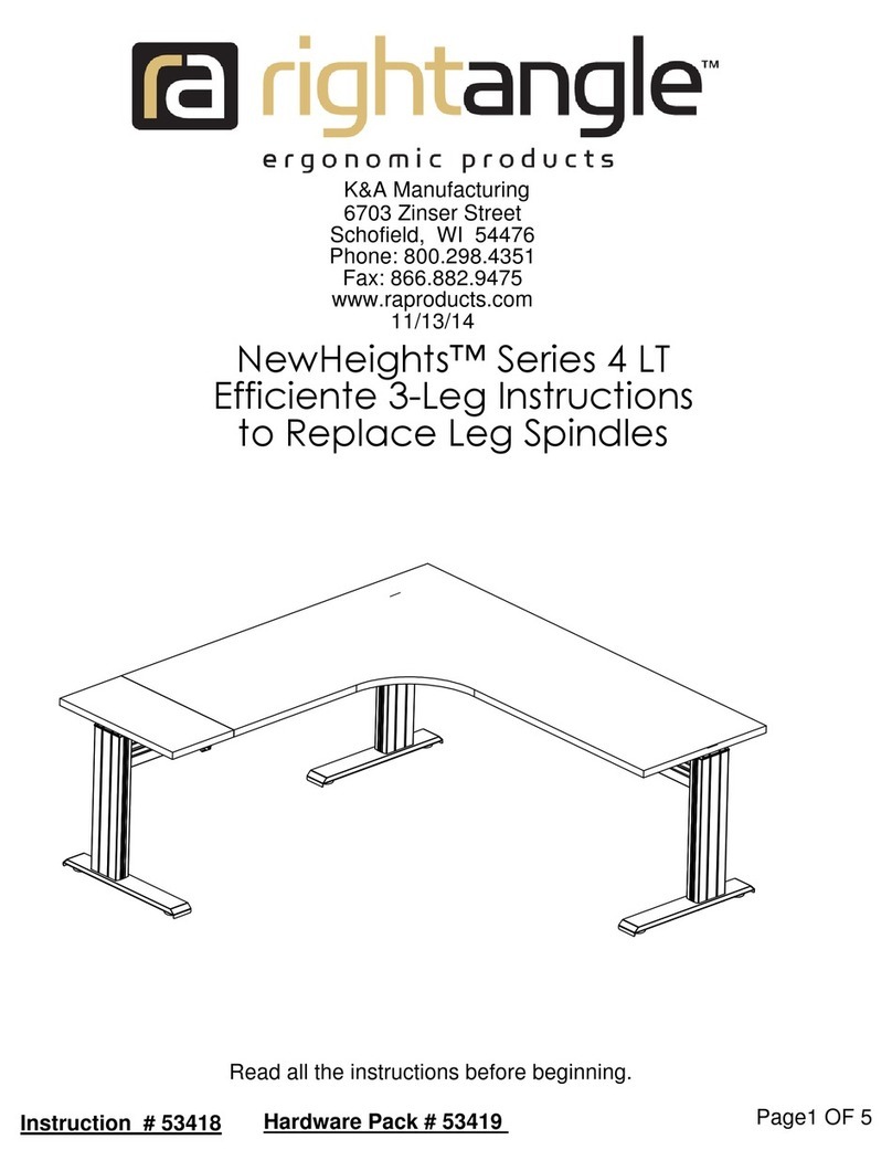
RIGHT ANGLE R-Style Modesty Panel User manual
RIGHT ANGLE

RIGHT ANGLE R-Style Modesty Panel User manual

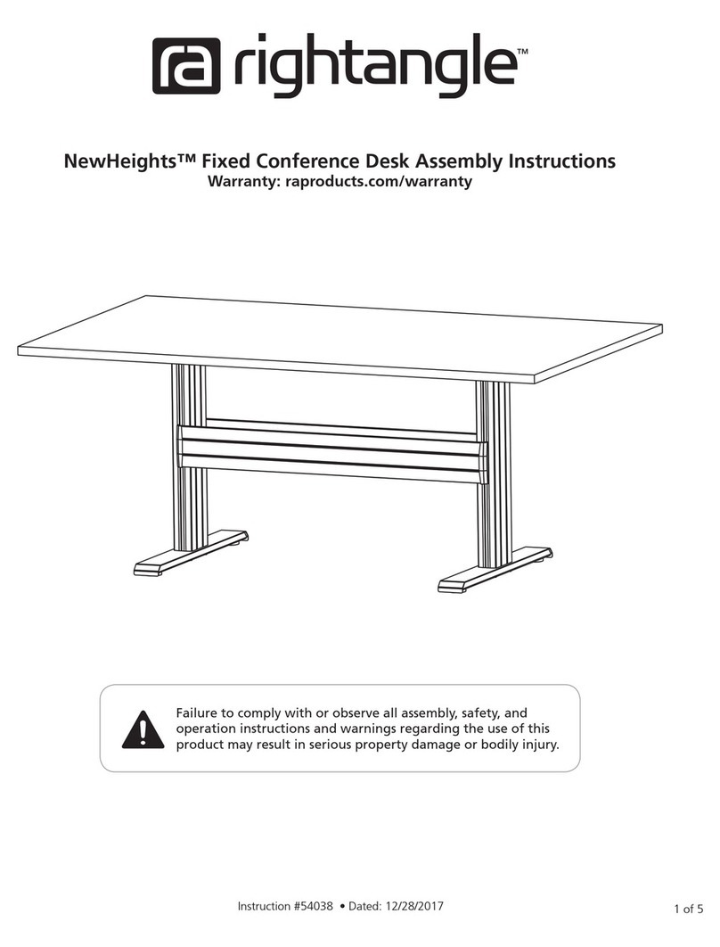
RIGHT ANGLE NewHeights Fixed Conference Desk User manual

RIGHT ANGLE

RIGHT ANGLE NewHeights Fixed Conference Desk User manual

RIGHT ANGLE R-Style Corner Diagonal 50648 User manual

RIGHT ANGLE

RIGHT ANGLE R-Style Corner Diagonal 50648 User manual

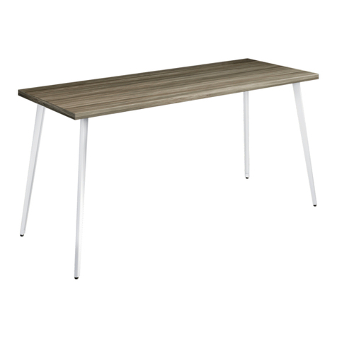
RIGHT ANGLE NewHeights Series User manual
RIGHT ANGLE

RIGHT ANGLE NewHeights Series User manual

RIGHT ANGLE R-Style Romeo Flip User manual

RIGHT ANGLE

RIGHT ANGLE R-Style Romeo Flip User manual

RIGHT ANGLE 53451 User manual

RIGHT ANGLE

RIGHT ANGLE 53451 User manual

RIGHT ANGLE NewHeights Electric Height Adjustable... User manual

RIGHT ANGLE

RIGHT ANGLE NewHeights Electric Height Adjustable... User manual

RIGHT ANGLE NewHeights 4 XT Series User manual

RIGHT ANGLE

RIGHT ANGLE NewHeights 4 XT Series User manual

RIGHT ANGLE R-Style Beam User manual

RIGHT ANGLE

RIGHT ANGLE R-Style Beam User manual

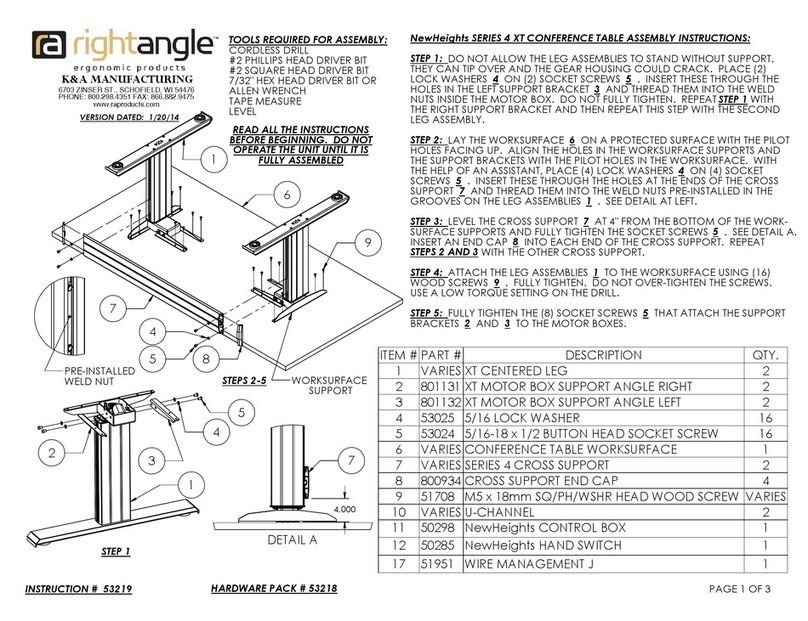
RIGHT ANGLE Eficiente LT Parts list manual
RIGHT ANGLE

RIGHT ANGLE Eficiente LT Parts list manual

RIGHT ANGLE NewHeights 4 Series User manual

RIGHT ANGLE

RIGHT ANGLE NewHeights 4 Series User manual

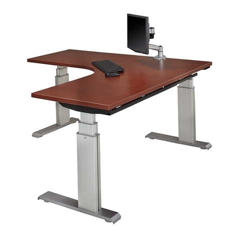
RIGHT ANGLE 48 HALF MOON ON R-STYLE User manual
RIGHT ANGLE

RIGHT ANGLE 48 HALF MOON ON R-STYLE User manual

Popular Indoor Furnishing manuals by other brands

Next SLOANE 404160 Assembly instructions

Next

Next SLOANE 404160 Assembly instructions

Novogratz DA8054C instruction manual

Novogratz

Novogratz DA8054C instruction manual

Kimball Office Footprint Bevel Profile Highback Organizer Assembly instructions

Kimball Office

Kimball Office Footprint Bevel Profile Highback Organizer Assembly instructions

Dorel Ameriwood 5234012PCOM manual

Dorel

Dorel Ameriwood 5234012PCOM manual

Habitat 886/9542 quick start guide

Habitat

Habitat 886/9542 quick start guide

Smart Comfort SADLER LIFT CHAIR Assembly instructions

Smart Comfort

Smart Comfort SADLER LIFT CHAIR Assembly instructions

HOME MERIDIAN 155-A283-016-042 manual

HOME MERIDIAN

HOME MERIDIAN 155-A283-016-042 manual

Delta Children BB86658SM-1162 Assembly instructions

Delta Children

Delta Children BB86658SM-1162 Assembly instructions

Ventura Mayfair Assembly instructions

Ventura

Ventura Mayfair Assembly instructions

Germania Hangevitrine 1502 Assembly instruction

Germania

Germania Hangevitrine 1502 Assembly instruction

Furinno NW889 quick start guide

Furinno

Furinno NW889 quick start guide

Blanco BLANCOPRECISION 512-747 Specification sheet

Blanco

Blanco BLANCOPRECISION 512-747 Specification sheet

VITRA Dancing Wall Assembly instructions

VITRA

VITRA Dancing Wall Assembly instructions

Lightolier LYTECASTER REFLECTOR TRIM installation instructions

Lightolier

Lightolier LYTECASTER REFLECTOR TRIM installation instructions

Till-Hilft 87265.310 installation instructions

Till-Hilft

Till-Hilft 87265.310 installation instructions

modway MOD-5363 quick start guide

modway

modway MOD-5363 quick start guide

Fumagalli DORY user manual

Fumagalli

Fumagalli DORY user manual

Riverside Furniture Clinton Hill 47230 Assembly instructions

Riverside Furniture

Riverside Furniture Clinton Hill 47230 Assembly instructions

manuals.online logo
manuals.online logoBrands
  • About & Mission
  • Contact us
  • Privacy Policy
  • Terms and Conditions

Copyright 2025 Manuals.Online. All Rights Reserved.