manuals.online logo
Brands
  1. Home
  2. •
  3. Brands
  4. •
  5. RIGHT ANGLE
  6. •
  7. Indoor Furnishing
  8. •
  9. RIGHT ANGLE 4 Vuelta Series User manual

RIGHT ANGLE 4 Vuelta Series User manual

Page1 OF 12
Instruction # 53552
Hardware Pack # 53555
K&A Manufacturing
6703 Zinser Street
Schofield, WI 54476
Phone: 800.298.4351
Fax: 866.882.9475
www.raproducts.com
Version Dated: 7/8/16
Read all the instructions before beginning.
Series 4 Vuelta 3-Leg Crank Height
Adjustable Workstation Assembly Instructions
Leg B Center Leg
Hex Drive Faces Right
Cage Nuts For Drive
Gear In Worksurface
Support
Hex Drive
Cage Nuts
4
Leg C Right Leg
Hex Drive Faces Left
Hex Rod Protrudes
Out of Front
Hex Drive
Hex Rod
9
Leg A Left Leg
Hex Drive Faces Right
Hex Drive
11
Page 2 OF 12
K&A Manufacturing
6703 Zinser Street Schofield, WI 54476
Phone: 800.298.4351
Fax: 866.882.9475
www.raproducts.com
Instruction # 53552
The drawing below shows how to distinguish the left, center, and right leg assemblies
from each other.
Page 3 OF 12
K&A Manufacturing
6703 Zinser Street Schofield, WI 54476
Phone: 800.298.4351
Fax: 866.882.9475
www.raproducts.com
Hardware Pack 53555 Drawn Actual Size
Instruction # 53552
51708
53013
53055
53638 53194
800934
7
16
15
6
13
3
Tools Required For Assembly:
Power Driver W/Adjustable Torque
#2 Phillips Head Driver Bit
#2 Square Head Driver Bit
3/16" Hex Head Driver Bit or
Allen Wrench
Adjustable Wrench
Tape Measure
Level
ITEM #
PART #
DESCRIPTION
QTY.
1
Varies
Series 4 Worksurface
1
2 800352
3x5 Worksurface Joiner Plate
1
3 51708
M5 x 18mm (7/8") Sq/Ph/Wshr Head Wood Screw
Varies
4
Varies
Center Crank Leg Assembly
1
5 801438
Differential Box Bracket Assembly
1
6 53013
Split Lock Washer 1/4"
2
7 53055
Socket Head Cap Screw 1/4-20 x 7/16
2
8
Varies
S4 Crank Hex Rod
1
9
Varies
Right Crank Leg Assembly
1
10
Varies
S4 Crank Return Side Hex Rod
1
11
Varies
Left Crank Leg Assembly
1
12
Varies
Series 4 Cross Support
1
13 53638
5/16-18 x 3/8 Button Head Socket Screw
10
15 800934
Cross Support End Cap
4
16 53194
5/16-18 Weld Nut 1.375" CL'S
2
17 801218
Series 4 3-Leg Cross Support L Bracket
1
18
Varies
LT U-Channel
Varies
19
Varies
S 4 Crank/ Bracket/Clamp Assembly
1
20
Varies
Series 4 Cross Support
1
A
B
Steps 1-3
Front
DETAIL A
4
83
6
7
1
5
Worksurface Support
DETAIL B
3
21
Page 4 OF 12
K&A Manufacturing
6703 Zinser Street Schofield, WI 54476
Phone: 800.298.4351
Fax: 866.882.9475
www.raproducts.com
Instruction # 53552
Step 1:
Lay the worksurface(s)
1
on a protected
surface with the pilot holes facing up. If your work-
surface has a seam, lay the joiner plate
2
centered
on the seam and about 3" from the front. Attach it
with (8) wood screws
3
. No pilot holes are provided.
Do not over-tighten the screws. Use a low torque
setting on the power driver.
Step 2:
Place the center leg
4
on the worksurface
1
aligning the holes in the worksurface
support with the pilot holes in the worksurface. The hole for the hex drive must face in.
Attach the leg assembly with (4) wood screws
3
in the outside corners. Leave the screws
loose by about 1/8" so you can adjust the cross support
12
later.
Step 3:
Insert the hex rod
8
that is 5" shorter than the worksurface through the differential
gear and bracket
5
and into the hex drive near the top of the center leg assembly
4 .
Align the holes in the differential box bracket with the cage nuts in the worksurface support.
Place (2) washers
6
on (2) socket screws
7
. Align the holes in the differential bracket
with the cage nuts in the worksurface support. Insert the socket screws through the
bracket assembly and thread them into the cage nuts. Fully tighten.
1
98
10
11
3
Steps 4 & 5
Page 5 OF 12
K&A Manufacturing
6703 Zinser Street Schofield, WI 54476
Phone: 800.298.4351
Fax: 866.882.9475
www.raproducts.com
Instruction # 53552
Step 4:
Place the right leg assembly
9 on the
worksurface
1
inserting the hex rod into the hex drive
on the leg. You may need to turn the hex rod slightly
to align it with the hex drive. It should take less than
1/6 of a turn to accomplish this. If you turn it more than
1/6 of a turn, the legs will be at different heights and
the worksurface will not be level. Align the holes in the worksurface support with the pilot
holes in the worksurface and attach the leg assembly with (4) wood screws
3
loosely as
you did in Step 2.
Step 5:
Insert the remaining hex rod
10
into the differential drive. Place the left leg
assembly
11
on the worksurface inserting the other end of the hex rod into the hex
drive near the top of the leg assembly. You may need to turn the hex rod as you did in
Step 4. Attach the leg assembly loosely with (4) wood screws
3
as you did in Steps
2 and 4.
L
Page 6 OF 12
Instruction # 53552
Step 6:
With the help of an assistant align the
cross support that is 5" shorter than the work-
surface with the stickers on both leg assemblies.
See below. Insert (4) socket screws
13
through
the holes in the ends of the cross support and
thread them into the weld nuts that are held in
place by the stickers. See page 7. Do not fully
tighten. Check that the cross support is level and
parallel to the worksurface. Fully tighten the
socket screws.
All three legs.
Step 6
C
9
4
Detail C
Pre-installed
Weld Nut
12
13
16
15
Page 7 OF 12
K&A Manufacturing
6703 Zinser Street Schofield, WI 54476
Phone: 800.298.4351
Fax: 866.882.9475
www.raproducts.com
Instruction # 53552
Step 7:
Slide a weld nut
16
into the groove in the back of the cross support
12
. The
projections on the weld nut must face outward.
Step 8:
Insert an end cap
15
into each end of the cross support
12 .
Steps 7 & 8
E
Detail E
13
15
Steps 11 & 12
11
13
15
17
13
20
16
Build this as a subassembly
before installing it on the
workstation.
Steps 9 & 10
Page 8 OF 12
K&A Manufacturing
6703 Zinser Street Schofield, WI 54476
Phone: 800.298.4351
Fax: 866.882.9475
www.raproducts.com
Instruction # 53552
Step 9:
Build the subassembly shown below. Slide a
weld nut
16
into the groove on the front of the cross
support
20
. The projections on the weld nut must face
out. Insert (2) socket screws
13
through the holes on the
wide side of the L bracket
17
and thread them into the
weld nut. Do not fully tighten.
Step 10:
Insert an end cap
15
into the end of the cross support
20.
Step 11:
Insert (2) socket screws
13
through the holes on the narrow side of the L
bracket
17
and thread them into the weld nut in the groove on the first cross support
16.
See Detail E. Do not fully tighten.
Step 12:
Align the cross support
20
with the sticker on the third leg assembly
11
. See
page 6. Insert (2) socket screws
13
through the holes in the end of the cross support
20
and thread them into the weld nut held in place by the sticker. Do not fully tighten. Make
sure the cross support is level and parallel with the edge of the worksurface. Fully tighten
all the socket screws. Insert an end cap
15
into the end of the cross support.
3
3
Steps 13-14
18 18
Page 9 OF 12
K&A Manufacturing
6703 Zinser Street Schofield, WI 54476
Phone: 800.298.4351
Fax: 866.882.9475
www.raproducts.com
Instruction # 53552
Step 13:
Fully tighten the wood screws
3
attaching the leg assemblies
4, 9, and 11.
to the worksurface
1
. Add (4) more wood
screws to each leg assembly. Fully tighten.
Step 14:
Align the holes in the u-channels
18
with the pilot holes in the worksurface
1.
Attach them with (6-12) wood screws
3
in each u-channel. Fully tighten.
C
Step 15
Note:
The position of the
crank handle can be adjusted
in or out by loosening the screw
in the clamp and sliding the
crank handle to the desired
position. Place the clamp
against the back of the
bracket and re-tighten
the screw.
9
1
19
3
Detail C
Hex Rod
DETAIL D
To Face of Bracket
M
.125-.250
.375
Page 10 OF 12
K&A Manufacturing
6703 Zinser Street Schofield, WI 54476
Phone: 800.298.4351
Fax: 866.882.9475
www.raproducts.com
Instruction # 53552
Step 15:
Slide the crank/bracket/clamp assembly
19
onto the hex rod protruding from the front of the right
leg assembly
9
. Align the holes in the bracket with
the pilot holes in the worksurface
1
. Attach it with
(4) wood screws
3 .
W
Step 16
DETAIL W
SCALE 1 : 4
Leveling Glide
Page 11 OF 12
K&A Manufacturing
6703 Zinser Street Schofield, WI 54476
Phone: 800.298.4351
Fax: 866.882.9475
www.raproducts.com
Instruction # 53552
Step 16:
With the help of an assistant, set the workstation upright in its final location.
Level the workstation if required by turning the leveler glides clockwise (from the top) on
the low corners of the unit. If your workstation has casters, level it by turning the bolts at
the top of the casters.
A
B
C
D
E
Your worksurface may
be different than the
one shown here.
Side View
(Track will be at an angle
when installation is finished.)
E
A
Page 12 OF 12
K&A Manufacturing
6703 Zinser Street Schofield, WI 54476
Phone: 800.298.4351
Fax: 866.882.9475
www.raproducts.com
Instructions To Install a Track on a Series 4 LT
Workstation:
Step 1:
Place the front of the track
A
against the
bottom of the worksurface and the back of the track
against the u-channel.
Instruction # 53552
Step 2:
Align the holes in the track
A
with one set of pilot holes in the u-channel
E
keeping the front of the track 1/8"-5/8" from the front of the worksurface. Place (2)
washers
B
on (2) self drilling screws
C
. Drive them through the track and into the
u-channel.
Step 3:
Attach the front of the track
A
to the worksurface using (2) wood screws
D
. Do
not over-tighten the wood screws. Use a low torque setting on the power driver.
Step 4:
Complete the installation using the instructions that came with the product you
are installing.
If the workstation leg assemblies are at uneven heights, it is usually caused by an
improperly installed hex rod. Disassemble one of the legs that point in the same direction
from the worksurface and make sure both ends of the hex rods are properly engaged in the
hex drives near the top of the leg assemblies.
Troubleshooting:
If you have problems with the table operation, contact RightAngle™
service at 800-298-4351 or [email protected].
ITEM #
PART #
DESCRIPTION
QTY.
A
Varies
Track Assembly
1
B
52336
3/16" Aluminum Rivet Washer .198 x .510 x .067
2
C
52678
8-18X1/2 Phillips Pan Self Drill Screw
2
D
51708
M5 x 18mm (7/8") Sq/Ph/Wshr Head Wood Screw
2
E
Varies
LT U-channel
1

Other RIGHT ANGLE Indoor Furnishing manuals
RIGHT ANGLE NewHeights Series User manual

RIGHT ANGLE

RIGHT ANGLE NewHeights Series User manual

RIGHT ANGLE R-Style Screw Height Adjustable User manual

RIGHT ANGLE

RIGHT ANGLE R-Style Screw Height Adjustable User manual

RIGHT ANGLE R-STYLE WORKSTATION 50643 User manual

RIGHT ANGLE

RIGHT ANGLE R-STYLE WORKSTATION 50643 User manual

RIGHT ANGLE Hover Helium Junior User manual
RIGHT ANGLE

RIGHT ANGLE Hover Helium Junior User manual

RIGHT ANGLE NewHeights Fixed Conference Desk User manual

RIGHT ANGLE

RIGHT ANGLE NewHeights Fixed Conference Desk User manual

RIGHT ANGLE R-Style Romeo Flip User manual

RIGHT ANGLE

RIGHT ANGLE R-Style Romeo Flip User manual

RIGHT ANGLE R-Style Tango User manual

RIGHT ANGLE

RIGHT ANGLE R-Style Tango User manual

RIGHT ANGLE NewHeights 4 LT Series User manual

RIGHT ANGLE

RIGHT ANGLE NewHeights 4 LT Series User manual

RIGHT ANGLE NewHeight 4 Series User manual

RIGHT ANGLE

RIGHT ANGLE NewHeight 4 Series User manual

RIGHT ANGLE 53451 User manual

RIGHT ANGLE

RIGHT ANGLE 53451 User manual

RIGHT ANGLE R-Style T-Base Table User manual

RIGHT ANGLE

RIGHT ANGLE R-Style T-Base Table User manual

RIGHT ANGLE R-Style Beam User manual

RIGHT ANGLE

RIGHT ANGLE R-Style Beam User manual

RIGHT ANGLE NewHeights Laminate Footshelf User manual
RIGHT ANGLE

RIGHT ANGLE NewHeights Laminate Footshelf User manual

RIGHT ANGLE NewHeights Electric Height Adjustable Conference... User manual

RIGHT ANGLE

RIGHT ANGLE NewHeights Electric Height Adjustable Conference... User manual

RIGHT ANGLE R-Style 52822 User manual

RIGHT ANGLE

RIGHT ANGLE R-Style 52822 User manual

RIGHT ANGLE NewHeights 4 Series User manual
RIGHT ANGLE

RIGHT ANGLE NewHeights 4 Series User manual

RIGHT ANGLE NewHeights 4 XT Series Parts list manual

RIGHT ANGLE

RIGHT ANGLE NewHeights 4 XT Series Parts list manual

RIGHT ANGLE Eficiente LT Parts list manual

RIGHT ANGLE

RIGHT ANGLE Eficiente LT Parts list manual

RIGHT ANGLE 48 HALF MOON ON R-STYLE User manual

RIGHT ANGLE

RIGHT ANGLE 48 HALF MOON ON R-STYLE User manual

RIGHT ANGLE NewHeights Series User manual

RIGHT ANGLE

RIGHT ANGLE NewHeights Series User manual

RIGHT ANGLE 310CPU User manual

RIGHT ANGLE

RIGHT ANGLE 310CPU User manual
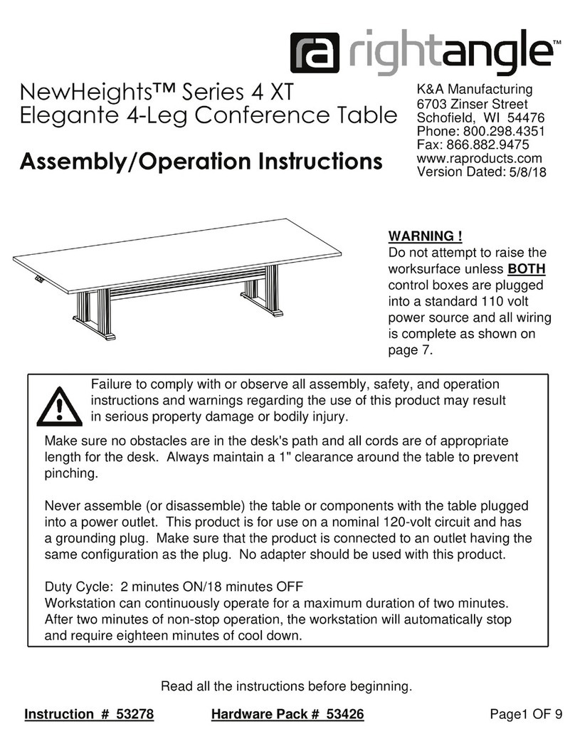
RIGHT ANGLE R-Style Custom C Leg Base with Side Stationary... User manual

RIGHT ANGLE

RIGHT ANGLE R-Style Custom C Leg Base with Side Stationary... User manual

RIGHT ANGLE NewHeights Gas Lift Adjustable SkateDesk User manual

RIGHT ANGLE

RIGHT ANGLE NewHeights Gas Lift Adjustable SkateDesk User manual

RIGHT ANGLE NewHeights 4 XT Series User manual

RIGHT ANGLE

RIGHT ANGLE NewHeights 4 XT Series User manual

Popular Indoor Furnishing manuals by other brands

ManoMano AGG533 Assembly instructions

ManoMano

ManoMano AGG533 Assembly instructions

MSI MAG CH120 quick start guide

MSI

MSI MAG CH120 quick start guide

Kingsbury 71495115 user manual

Kingsbury

Kingsbury 71495115 user manual

Costway CB10493US manual

Costway

Costway CB10493US manual

DINAZA DINNING TABLE WITH STORAGE Assembly instructions

DINAZA

DINAZA DINNING TABLE WITH STORAGE Assembly instructions

Coaster 223391Q B1 Assembly instructions

Coaster

Coaster 223391Q B1 Assembly instructions

Knight Anvil Eclipse Desk Assembly instructions

Knight

Knight Anvil Eclipse Desk Assembly instructions

MAISONS DU MONDE LISBOA 186604 manual

MAISONS DU MONDE

MAISONS DU MONDE LISBOA 186604 manual

Ashford Hobby Bench 2 instructions

Ashford

Ashford Hobby Bench 2 instructions

Avenue Six OFFICE STAR SAVANNA SAV2 quick start guide

Avenue Six

Avenue Six OFFICE STAR SAVANNA SAV2 quick start guide

Forte RAVEN RVXB221 Assembling Instruction

Forte

Forte RAVEN RVXB221 Assembling Instruction

Henn&Hart TV1874 Assembly instructions

Henn&Hart

Henn&Hart TV1874 Assembly instructions

Twin-Star International TRESANTI CC30-9643 Assembly instructions

Twin-Star International

Twin-Star International TRESANTI CC30-9643 Assembly instructions

Wenger Conductor’s Chair Assembly instructions

Wenger

Wenger Conductor’s Chair Assembly instructions

Coaster 205101KW Assembly instructions

Coaster

Coaster 205101KW Assembly instructions

DREAMS HART LIFESTYLE BED SLEEPMOTION manual

DREAMS

DREAMS HART LIFESTYLE BED SLEEPMOTION manual

Seville Classics OFF65854 Assembly instruction

Seville Classics

Seville Classics OFF65854 Assembly instruction

Kvik MU926 manual

Kvik

Kvik MU926 manual

manuals.online logo
manuals.online logoBrands
  • About & Mission
  • Contact us
  • Privacy Policy
  • Terms and Conditions

Copyright 2025 Manuals.Online. All Rights Reserved.