8 KNX-SA41 • KNX-SA24 SATEL
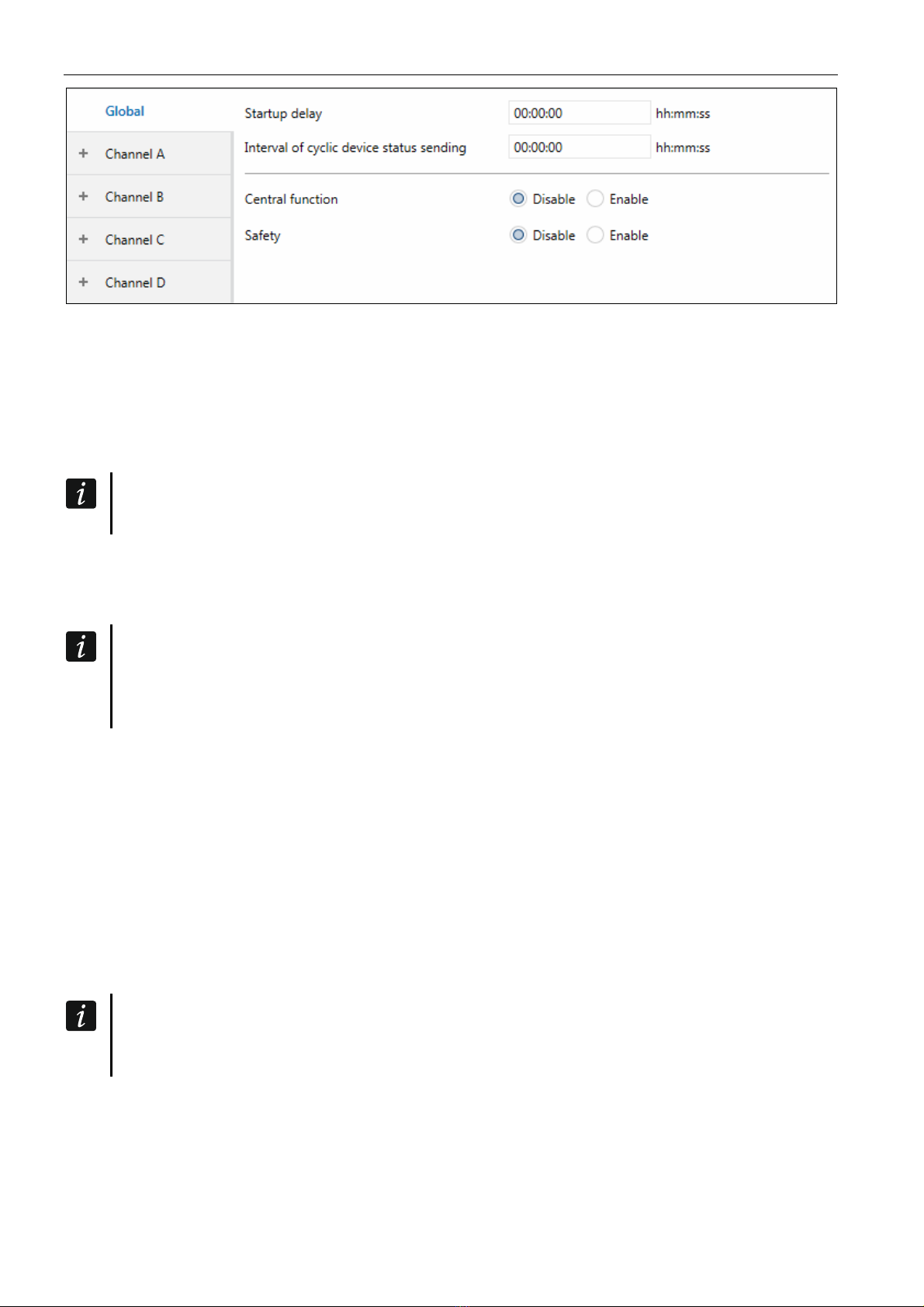
Startup delay – time period by which the module startup will be delayed after power-on.
Value 00:00:00 will disable the delay.
During the delay period the telegram handling is stopped and the channels do not change
their state. The module sends no telegrams to the KNX bus. After the delay expires, the
telegrams are sent and the state of channels is set according to the parameters defined. If
any telegrams are received from communication objects during the delay period, they will
be stored. Replies to these telegrams are sent after expiry of the delay time.
The startup delay may be used to reduce load on the KNX bus and supply circuit after
power-on.
Interval of cyclic device status sending – frequency with which a telegram is sent to the
bus by the “Device operation status” communication object with the module status
information. Information contained in the telegram makes it possible to monitor the module
operation by other devices on the KNX bus. Value 00:00:00 disables the sending.
Sending telegrams may be enabled either permanently, for continuous monitoring of
the module operation, or during testing only. If you do not want to load the bus with an
excessive number of telegrams, you can set the sending cycle time at the highest
possible value.
Central function – enables / disables the central function in the module (Disable / Enable).
Enabling the function will enable the “Switch function” communication object, which makes
it possible to control all the module channels. Each channel can respond in different way to
the state change of that object. Reaction of the channel is defined by means of the
“Reaction on central” parameter.
Safety– enables / disables the safety function in the module (Disable / Enable). Enabling the
function will enable the “Safety priority 1” communication object and display the “Safety”
tab.
4.2.1 Safety
You can define 3 “Safety priority n (n = 1, 2, 3)” objects. Reaction to a change of safety object
state can be defined for each channel.
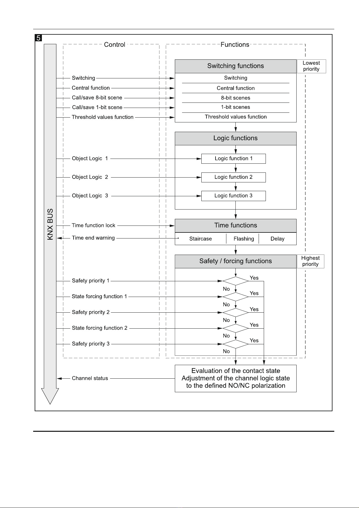
Remember that safety functions have the highest priority. The channel state set by
such a function can only be changed by another safety function or state forcing
function, provided these functions will have higher priority (see “Function priorities”).
You can define the monitoring time for each object. If a telegram with value opposite to the
activating value is received during the monitoring time, the time will run from the beginning
(reset). If no telegram is received during the monitoring time, the safety object will be
activated.