manuals.online logo
Brands
  1. Home
  2. •
  3. Brands
  4. •
  5. Sauder
  6. •
  7. Indoor Furnishing
  8. •
  9. Sauder 423032 User manual

Sauder 423032 User manual

NOTE: THIS INSTRUCTION
BOOKLET CONTAINS IMPORTANT
SAFETY INFORMATION.
PLEASE READ AND KEEP FOR
FUTURE REFERENCE.
English pg 1-14
Français pg 15-17
Español pg 18-20
Lot # 512081 12/11/17
Purchased: __________________
Be sure to give us a ring before
making any returns. 1-800-523-3987
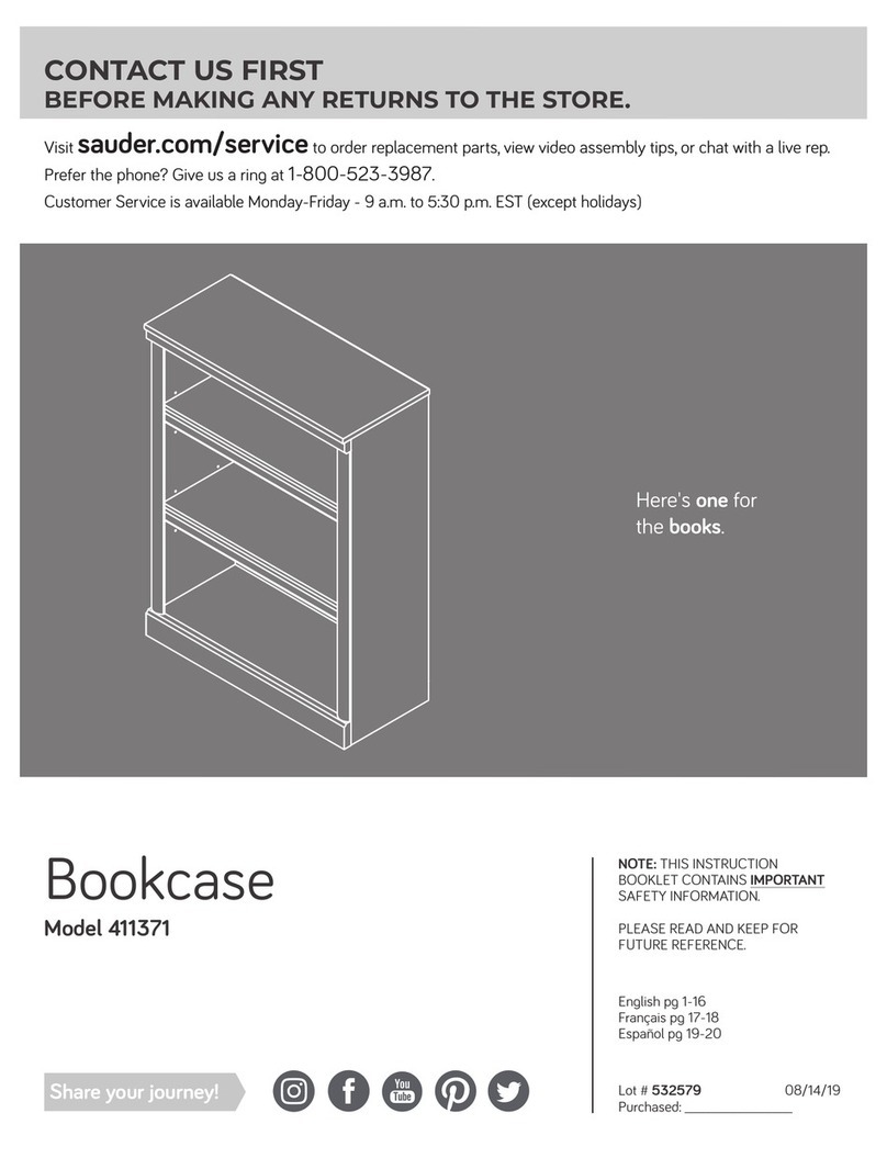
3-Shelf Bookcase
Model 423032
Need help? Visit Sauder.com to view video assembly tips or chat with a live rep.
Prefer the phone? Call 1-800-523-3987.
Share your journey!
sauder.com
The stories of your life.
Table of Contents Assembly Tools Required
3
4
5-14
15-17
18-20
21-22
23
Part Identification
Hardware Identification
Assembly Steps
Français
Español
Safety
Warranty
Hammer
Not actual size
No. 2 Phillips Screwdriver
Tip Shown Actual Size
423032 www.sauder.com/servicesPage 2
Skip the power trip.
This time.
Tape Measure
Part Identification Now you know
our ABCs.
423032www.sauder.com/services Page 3
åWhile not all parts are labeled, some of the parts will have a label or an inked letter on the edge
to help distinguish similar parts from each other. Use this part identification to help identify similar parts.
A RIGHT END (1)
B LEFT END (1)
E2 TOP (1)
F BOTTOM (1)
H2 BACK (1)
J ADJUSTABLE SHELF (2)
K END MOLDING (2)
M25 TOP MOLDING (1)
M48 BASE (1)
N SHELF MOLDING (2)
A
B
E2
F
J
H2
M25
N
M48
K
K
NJ
Hardware Identification
åScrews are shown actual size. You may receive extra hardware with your unit.
423032 www.sauder.com/servicesPage 4
ANGLE BRACKET - 5
44G
HIDDEN CAM - 8
1F CAM DOWEL - 8
2F
METAL PIN - 8
1R
CAM COVER - 4
19P HOLE PLUG - 3
80P
NAIL - 30
1N
BLACK 1-1/8" PAN HEAD SCREW - 3
9S
BLACK 9/16" LARGE HEAD SCREW - 11
1S
SAFETY STRAP - 1
Locate this nylon SAFETY
STRAP (60M) to be used
later in assembly. Do not
accidentally throw away.
60M SAFETY DRYWALL
ANCHOR - 1
61M
WASHER - 1
13M
Step 1 Look for this icon. It means a
video assembly tip is available at
www.sauder.com/services/tips
å Assemble your unit on a carpeted floor or on the empty
carton to avoid scratching your unit or the floor.
å Push eight HIDDEN CAMS (1F) into the ENDS (A and B)
and BOTTOM (F). Then insert the metal end of a CAM
DOWEL (2F) into each HIDDEN CAM.
423032www.sauder.com/services Page 5
A
B
F
Arrow
1F
2F
Insert the metal end of the CAM
DOWEL into the HIDDEN CAM.
Arrow
Do not tighten the HIDDEN CAMS in this step.
(8 used)
Step 2
423032 www.sauder.com/servicesPage 6
å Fasten the ENDS (A and B) to the BOTTOM (F). Tighten four
HIDDEN CAMS.
A
B
F
Start Tighten
Arrow
Minimum
190 degrees
Caution
Risk of damage or
injury. HIDDEN CAMS
must be completely
tightened. HIDDEN
CAMS that are not
completely tightened
may loosen, and parts
may separate. To
completely tighten:
Arrow
Maximum
210 degrees
Notched edge
Notched edge
These holes must be here.
Surface with
HIDDEN CAMS
Surface without
HIDDEN CAMS
Surface with
HIDDEN CAMS
Do not stand the unit upright without the
BACK fastened. The unit may collapse.
Caution
Step 3
423032www.sauder.com/services Page 7
å Fasten the SAFETY STRAP (60M) to the TOP (E2). Use a
BLACK 9/16" LARGE HEAD SCREW (1S).
å NOTE: Position the SAFETY STRAP (60M) exactly as shown.
å Fasten the TOP (E2) to the ENDS (A and B). Tighten four
HIDDEN CAMS.
A
B
Arrow
Minimum
190 degrees
Maximum
210 degrees
E2
Surface with holes
E2
60M
BLACK 9/16" LARGE HEAD SCREW
(1 used in this step)
1S
Surface with holes
Long finished edge
Step 4
å Fasten the TOP MOLDING (M25) to the TOP (E2). Use
three BLACK 1-1/8" PAN HEAD SCREWS (9S).
å NOTE: Do not overtighten the SCREWS into the TOP.
å Insert three HOLE PLUGS (80P) into the holes in the
TOP MOLDING (M25).
423032 www.sauder.com/servicesPage 8
E2
Curved edge
BLACK 1-1/8" PAN HEAD SCREW
(3 used in this step)
9S
80P
Remember:
Righty tighty.
Lefty loosey.
M25
å Slide the END MOLDINGS* (K) onto the notched edges of
the ENDS (A and B).
å *U.S. Patent No. 5,499,886
Step 5
423032www.sauder.com/services Page 9
A
B
K
K
Slide the END MOLDINGS (K)
onto the notched edges.
Notched edge
Notched edge
The large groove is
closer to this edge.
The large groove is
closer to this edge.
Step 6
å Fasten five ANGLE BRACKETS (44G) to the ENDS (A
and B) and BOTTOM (F). Use five BLACK 9/16" LARGE
HEAD SCREWS (1S).
å NOTE: Be sure the edges of the ANGLE BRACKETS are
even with the edges of the ENDS and BOTTOM.
å Fasten the BASE (M48) to the ANGLE BRACKETS. Use
five BLACK 9/16" LARGE HEAD SCREWS (1S).
423032 www.sauder.com/servicesPage 10
BLACK 9/16" LARGE HEAD SCREW
(10 used in this step)
1S
F
B
A
44G
44G
44G
Wide edge
M48
å Carefully turn your unit over onto its front edges. Unfold
the BACK (H2) and lay it over your unit.
å A perforation in the BACK (H2) has been provided for
access to the SAFETY STRAP (60M). Punch out the
perforation and push the SAFETY STRAP through the hole.
å Make equal margins along all four edges of the BACK (H2).
Push on opposite corners of your unit if needed to make
it "square".
å Fasten the BACK (H2) to your unit using the NAILS (1N).
The NAILS should be 5" apart and 1/4" in from the edges.
Step 7
423032www.sauder.com/services Page 11
1/4"
5"
NAIL
(30 used in this step)
1N
Do not stand the unit upright without the
BACK fastened. The unit may collapse.
Caution
H2
Unfinished
surface
Before fastening the
BACK, punch out the
perforation and push
the SAFETY STRAP
through the hole.
60M
Step 8
å Carefully stand your unit upright in its final position against a wall.
å NOTE: Do not turn the SAFETY DRYWALL ANCHOR (61M) into a wall stud. If you prefer to fasten the SAFETY
STRAP (60M) to a wall stud, go to your local hardware store for proper hardware.
å INSTALLATION INSTRUCTIONS:
1. Insert the SAFETY DRYWALL ANCHOR (61M) through the WASHER (13M) and the end of the SAFETY STRAP (60M).
2. Using a Phillips screwdriver or a hand drill, press the screw slightly onto the drywall just below the top surface of your
unit so the SAFETY STRAP will not be visible.
3. Apply pressure; turn the screw until a pilot hole is made and the nylon sheath slips through.
4. Turn the screw until it is flush against the wall and you feel a firm resistance.
5. Continue to turn until the screw starts spinning freely.
å NOTE: Before moving your unit to a dierent location, unscrew the SAFETY DRYWALL ANCHOR (61M) from your wall.
The nylon sheath will remain behind your wall.
61M
13M
60M
423032 www.sauder.com/servicesPage 12
Pro Tip: Lift with your
legs. And, you know,
your arms.
StepStep 9
å Slide a SHELF MOLDING* (N) onto the notched edge of
each ADJUSTABLE SHELF (J).
å Repeat this step for the other ADJUSTABLE SHELF (J).
å * U.S. Patent No. 5,499,886
J
N
Slide the SHELF MOLDING (N)
onto the notched edge.
Notched edge
These surfaces
should be even.
The large groove is
closer to this edge.
423032www.sauder.com/services Page 13
Step
423032 www.sauder.com/servicesPage 14
å Insert the METAL PINS (1R) into the hole locations of your choice in the ENDS (A and B). Set the
ADJUSTABLE SHELVES (J) onto the METAL PINS.
å Using your hammer, gently tap a CAM COVER (19P) onto each visible HIDDEN CAM.
å NOTE: Please read the back pages of the instruction booklet for important safety information.
å This completes assembly. Clean with your favorite furniture polish or a damp cloth. Wipe dry.
Step 10
A
B
J
J
1R
19P
(4 used)
(8 used)
To cover HIDDEN CAMS
And to celebrate, why not share your success story?
25 lbs.
25 lbs.
50 lbs.
35 lbs.
A l’usage exclusif du
Canada Noter la date
d’achat de cet élément
et conserver le livret
pour future référence.
Pour contacter Sauder
en ce qui concerne cet
élément, faire référence
au numéro de lot et
numéro de modèle en
appelant notre numéro
sans frais.
Lot nº : ____________
Date de
l’achat: ____________
LISTE DE PIÈCES
REFERENCE DESCRIPTION QUANTITÉ
LISTE DE PIÈCES
REFERENCE DESCRIPTION QUANTITÉ
NOUS SOMMES LA POUR VOUS AIDER!
Nous faisons de notre mieux pour nous assurer que votre meuble
arrive dans d’excellentes conditions. Nos représentants du service
Clientèle sont aimables et prêts à vous aider au cas où une pièce
aurait été endommagée ou manquerait (ou si vous aviez besoin
d’aide pour l’assemblage). NE RAMENEZ PAS LE MEUBLE AU
MAGASIN. Au Canada, composez ce numéro d’appel gratuit:
1-800-523-3987
Du lundi au vendredi, de 9 heures du matin à
5:30 heures du soir (horaire Côte Est)
(sauf jours fériés)
Si une pièce a besoin d’être remplacée, la pièce de remplacement
sera envoyée dans les 48 heures. (Sauf week-ends et jours fériés)
Utilisez les instructions d’assemblage en français avec les
schémas étape par étape du manuel d’instruction en anglais.
Chaque étape en français correspond à la même étape
en anglais. La pièce devant être attachée à l’élément est
représentée en gris sur les schémas de chaque étape pour plus
de précision. Comparer la “Liste de pièces” ci-dessous avec
la “PART IDENTIFICATION” du manuel en anglais pour vous
familiariser avec les pièces avant l’assemblage.
REMARQUE : CE MANUEL D’INSTRUCTIONS CONTIENT
D’IMPORTANTES INFORMATIONS RELATIVES À LA SÉCURITÉ.
À LIRE ET CONSERVER POUR TOUTE RÉFÉRENCE FUTURE.
Bibliothèque avec 3 TablettesModèle 423032
1F EXCENTRIQUE ESCAMOTABLE.....................8
2F CHEVILLE D’EXCENTRIQUE...............................8
44G CONSOLE À ÉQUERRE.........................................5
13M RONDELLE........................................................................1
60M SANGLE DE SÉCURITÉ...........................................1
Localiser cette SANGLE DE SÉCURITÉ (60M)
à utiliser ultérieurement dans l’assemblage.
Ne pas les jeter accidentellement.
61M DISPOSITIF DE SÉCURITÉ
POUR PLACOPLÂTRE..............................................1
1N CLOU ................................................................................30
19P COUVERCLE D’EXCENTRIQUE.......................4
80P CACHE-TROUS.............................................................3
1R GOUPILLE EN MÉTAL.............................................8
1S VIS TÊTE LARGE 14 mm NOIRE....................11
9S VIS TÊTE GOUTTE DE SUIF
28 mm NOIRE...............................................................3
A EXTRÉMITÉ DROITE..................................................1
B EXTRÉMITÉ GAUCHE...............................................1
E2 DESSUS...............................................................................1
F DESSOUS...........................................................................1
H2 ARRIÈRE ..............................................................................1
J TABLETTE RÉGLABLE............................................2
K MOULURE D’EXTRÉMITÉ.....................................2
M25
MOULURE DE DESSUS..........................................1
M48
SOCLE..................................................................................1
N MOULURE DE TABLETTE ....................................2
423032www.sauder.com/services Page 15
ÉTAPE 1
Ne pas serrer les EXCENTRIQUES ESCAMOTABLES à
cette étape.
Assembler l’élément sur un sol à moquette ou sur le carton vide
pour éviter d’endommager l’élément ou le sol.
Enfoncer huit EXCENTRIQUES ESCAMOTABLES (1F) dans
les EXTRÉMITÉS (A et B) et le DESSOUS (F). Ensuite, insérer
une CHEVILLE D’EXCENTRIQUE (2F) dans chaque
EXCENTRIQUE ESCAMOTABLE.
ÉTAPE 2
Attention : Ne pas relever l’élément dans sa position verticale
avant d’avoir fixé l’ARRIÈRE. L’élément risque de s’eondrer.
Fixer les EXTRÉMITÉS (A et B) au DESSOUS (F). Serrer quatre
EXCENTRIQUES ESCAMOTABLES.
Attention: Risque des dégâts ou blessures. Les Excentriques
Escamotables doivent être serrés à bloc. Les Excentriques
Escamotables que ne sont pas serrées à bloc peuvent desserrer
et les pièces peuvent séparer. Pour serrer à bloc, faire tourner
l'excentrique escamotable de 210 degrés.
ÉTAPE 4
Fixer la MOULURE DE DESSUS (M25) au DESSUS (E2). Utiliser
trois VIS NOIRES TÊTE GOUTTE DE SUIF 28 mm (9S).
REMARQUE : Ne pas trop serrer les VIS dans le DESSUS.
Insérer trois CACHE-TROUS (80P) dans les trous dans la
MOULURE DE DESSUS (M25).
ÉTAPE 5
Enfiler les MOULURES D’EXTRÉMITÉ (K) sur les chants crantés
des EXTRÉMITÉS (A et B).
* Brevet État Unis n_ 5.499.886
ÉTAPE 3
Fixer la SANGLE DE SÉCURITÉ (60M) au DESSUS (E2). Utiliser
une VIS TÊTE LARGE 14 mm NOIRE (1S).
REMARQUE : Placer la SANGLE DE SÉCURITÉ (60M) exactement
comme l'indique le schéma.
Fixer le DESSUS (E2) aux EXTRÉMITÉS (A et B). Serrer quatre
EXCENTRIQUES ESCAMOTABLES.
ÉTAPE 6
Fixer cinq CONSOLES À ÉQUERRE (44G) aux EXTRÉMITÉS (A
et B) et au DESSOUS (F). Utiliser cinq VIS NOIRES TÊTE
LARGE 14 mm (1S).
REMARQUE : S’assurer que les chants des CONSOLES À
ÉQUERRE sont à fleur des chants des EXTRÉMITÉS et
du DESSOUS.
Fixer le SOCLE (M48) aux CONSOLES À ÉQUERRE. Utiliser cinq
VIS NOIRES TÊTE LARGE 14 mm (1S).
423032 www.sauder.com/servicesPage 16
ÉTAPE 7
Attention : Ne pas relever l’élément dans sa position verticale
avant d’avoir fixé l’ARRIÈRE. L’élément risque de s’eondrer.
Avec précaution, retourner l’élément sur ses chants avant. Déplier
l’ARRIÈRE (H2) et le placer sur l’élément.
Une perforation a été prévue pour accès à travers l’ARRIÈRE (H2)
pour la SANGLE DE SÉCURITÉ (60M). Découper soigneusement la
perforation et enfoncer la SANGLE DE SÉCURITÉ à travers le trou.
Veiller à avoir des marges égales le long des quatre chants de
l’ARRIÈRE (H2). Si besoin est, enfoncer sur les coins opposés de
l’élément pour s’assurer d’être "d’équerre".
Fixer l’ARRIÈRE (H2) à l’élément à l’aide des CLOUS (1N). Les
CLOUS devraient être placés avec une séparation de 12.7 cm
et 6 mm en retrait des chants.
ÉTAPE 8
Relever, avec précaution, l'élément dans sa position verticale et
placer l'élément dans son emplacement final, contre un mur.
REMARQUE : Ne pas tourner le DISPOSITIF DE SÉCURITÉ POUR
PLACOPLÂTRE (61M) dans un montant mural. Si on préfère fixer
la SANGLE DE SÉCURITÉ (60M) à un montant mural, obtenir la
visserie appropriée auprès d’une quincaillerie locale.
INSTRUCTIONS D’INSTALLATION :
1. Insérer le DISPOSITIF DE SÉCURITÉ POUR PLACOPLÂTRE (61M)
à travers la RONDELLE (13M) et l'extrémité de la SANGLE
DE SÉCURITÉ (60M).
2. À l’aide d’un tournevis cruciforme ou d’une perceuse à main,
enfoncer la vis légèrement dans le Placoplatre juste en-dessous
de la surface supérieure de l’unité de sorte que la SANGLE DE
SÉCURITÉ ne soit pas visible.
3. Appliquer une certaine pression ; faire tourner la vis jusqu’à la
gaine en nylon glisse à travers.
4. Faire tourner la vis jusqu’à ce qu’elle soit à fleur du mur et
qu'une résistance ferme se fasse sentir.
5. Continuer de tourner jusqu’à ce que la vis commence à
pivoter librement.
REMARQUE : Avant de déplacer l’unité vers un emplacement
diérent, dévisser le DISPOSITIF DE SÉCURITÉ POUR
PLACOPLÂTRE (61M) du mur. La gaine en nylon restera derrière
le mur.
ÉTAPE 9
Enfiler une MOULURE DE TABLETTE* (N) sur le chant cranté de
chaque TABLETTE RÉGLABLE (J).
Répéter cette étape pour le autre TABLETTE RÉGLABLE (J).
* Brevet État Unis n_ 5.499.886
ÉTAPE 10
Insérer les GOUPILLES EN MÉTAL (1R) dans les trous
choisis dans les EXTRÉMITÉS (A et B). Poser les TABLETTES
RÉGLABLES (J) sur les GOUPILLES EN MÉTAL.
À l'aide d'un marteau, enfoncer un COUVERCLE D'EXCENTRIQUE (19P)
sur chaque EXCENTRIQUE ESCAMOTABLE visible.
REMARQUE : Prière de lire attentivement les importantes
informations concernant la sécurité qui figurent sur les pages
arrière du manuel d’instructions.
Ceci complète l’assemblage. Pour nettoyer, utiliser l’encaustique
pour meubles préférée ou un chion humide. Essuyer.
423032www.sauder.com/services Page 17
A l’usage exclusif du
Canada Noter la date
d’achat de cet élément
et conserver le livret
pour future référence.
Pour contacter Sauder
en ce qui concerne cet
élément, faire référence
au numéro de lot et
numéro de modèle en
appelant notre numéro
sans frais.
Lot nº : ____________
Date de
l’achat: ____________
LISTA DE PARTES
ITEM DESCRIPCIÓN CANTIDAD
ESTAMOS AQUI PARA AYUDAR!
Tratamos de asegurar que su mueble llega en condición excelente.
Nuestros representantes de Servicio al Cliente son amables y
listos para ayudarle con servicio rápido y eficiente si una parte
está defectuosa o ausente (o si necesita ayuda con el ensamblaje).
NO DEVUELVA LA UNIDAD A LA TIENDA. Llame este número sin
cargo:
1-800-523-3987
Lunes a viernes, 9:00 a.m. - 5:30 p.m.
Hora oficial del Este
(excepto días festivos)
Si requiere un repuesto de una parte, será enviado dentro de
48 horas (excepto los fines de semana y días festivos)
Use estas instrucciones de ensamblaje en español junto con las
figuras paso-a-paso provistas en el folleto inglés. Cada paso
en español corresponde al mismo paso en inglés. Se destacan
las figuras de cada paso con una tonalidad oscura para mostrar
precisamente cual parte se debe montar a la unidad. Compare
la “Lista de Part” abajo con la “Part Identification” en el folleto en
inglés para familiarizarse con Las partes de ensamblaje.
NOTA: ESTE FOLLETO DE INSTRUCCIONES CONTIENE
INFORMACIÓN IMPORTANTE SOBRE LA SEGURIDAD. POR
FAVOR LEA Y GUÁRDELO PARA REFERENCIA EN EL FUTURO.
1F EXCÉNTRICO ESCONDIDO ...............................8
2F PASADOR DE EXCÉNTRICO..............................8
44G SOPORTE ANGULAR..............................................5
13M ARANDELA........................................................................1
60M CORREA DE SEGURIDAD.....................................1
Ubique esta CORREA DE SEGURIDAD de
nailon (60M) que más tarde se utilizará
en el ensamblaje. No lo tire por accidente.
61M ANCLAJE DE SEGURIDAD PARA
EL DRYWALL....................................................................1
1N CLAVO.............................................................................30
19P CUBIERTA DE EXCÉNTRICO..............................4
80P TAPÓN DE AGUJERO..............................................3
1R ESPIGA DE METAL....................................................8
1S TORNILLO NEGRO DE CABEZA
GRANDE de 14 mm..................................................11
9S TORNILLO NEGRO DE CABEZA
REDONDA de 28 mm..............................................3
A EXTREMO DERECHO...............................................1
B EXTREMO IZQUIERDO............................................1
E2 PANEL SUPERIOR.......................................................1
F FONDO.................................................................................1
H2 DORSO.................................................................................1
J ESTANTE AJUSTABLE ............................................2
K MOLDURA DE EXTREMO.....................................2
M25
MOLDURA DE PANEL SUPERIOR..................1
M48
BASE ......................................................................................1
N MOLDURA DE ESTANTE.......................................2
LISTA DE PARTES
ITEM DESCRIPCIÓN CANTIDAD
Librería con 3 EstantesModelo 423032
423032 www.sauder.com/servicesPage 18
PASO 1
No apriete los EXCÉNTRICOS ESCONDIDOS en este paso.
Ensamble la unidad sobre un piso alfombrado o sobre el cartón
vacío para evitar rayar la unidad o el piso.
Empuje ocho EXCÉNTRICOS ESCONDIDOS (1F) dentro de
los EXTREMOS (A y B) y del FONDO (F). A continuación,
inserte un PASADOR DE EXCÉNTRICO (2F) dentro de cada
EXCÉNTRICO ESCONDIDO.
PASO 2
Precaución : No coloque la unidad en posición vertical hasta que
se fije el DORSO. La unidad podría caerse.
Fije los EXTREMOS (A y B) al FONDO (F). Apriete cuatro
EXCÉNTRICOS ESCONDIDOS.
Precaución: Riesgo de daños o heridas. Los Excéntricos Escondidos
deben apretarse completamente. Los Excéntricos Escondidos que
no se aprieten completamente se aflojarán y las partes pueden
separarse. Para apretar completamente, atornille el excéntrico
escondido 210 grados.
PASO 4
Fije la MOLDURA DE PANEL SUPERIOR (M25) al PANEL
SUPERIOR (E2). Utilice tres TORNILLOS NEGROS DE CABEZA
REDONDA de 28 mm (9S).
NOTA: No apriete en exceso los TORNILLOS en el PANEL SUPERIOR.
Insertar tres TAPONES DE AGUJEROS (80P) dentro de los
agujeros de la MOLDURA DE PANEL SUPERIOR (M25).
PASO 5
Deslice las MOLDURAS DE EXTREMO (K) sobre los bordes con
muesca de los EXTREMOS (A y B).
* Patente EE.UU. No. 5,499,886
PASO 3
Fije la CORREA DE SEGURIDAD (60M) al PANEL SUPERIOR (E2).
Utilice un TORNILLO NEGRO DE CABEZA GRANDE de 14 mm (1S).
NOTA: Coloque la CORREA DE SEGURIDAD (60M) exactamente
como se muestra.
Fije el PANEL SUPERIOR (E2) a los EXTREMOS (A y B). Apriete
cuatro EXCÉNTRICOS ESCONDIDOS.
PASO 6
Fije cinco SOPORTES ANGULARES (44G) a los EXTREMOS (A
y B) y al FONDO (F). Utilice cinco TORNILLOS NEGROS DE
CABEZA GRANDE de 14 mm (1S).
NOTA: Asegúrese que los bordes de los SOPORTES ANGULARES
estén nivelados con los bordes de los EXTREMOS y del FONDO.
Fije la BASE (M48) a los SOPORTES ANGULARES. Utilice cinco
TORNILLOS NEGROS DE CABEZA GRANDE de 14 mm (1S).
423032www.sauder.com/services Page 19
PASO 7
Precaución : No coloque la unidad en posición vertical hasta que
se fije el DORSO. La unidad podría caerse.
Cuidadosamente voltee la unidad para que repose sobre los
bordes delanteros. Desdoble el DORSO (H2) y colóquelo sobre
la unidad.
Se ha provisto una perforación para acceso a través del
DORSO (H2) para la CORREA DE SEGURIDAD (60M). Perforar la
perforación y empuje a través de la CORREA DE SEGURIDAD a
través el agujero.
Fije el DORSO (H2) de manera que los márgenes son iguales a lo
largo de los cuatro bordes. Empuje sobre las esquinas opuestas
de la unidad si es requerido para hacerla "cuadrada."
Fije el DORSO (H2) a la unidad utilizando los CLAVOS (1N). Debe
colocar los CLAVOS a una distancia de 12.7 cm el uno del otro
y a 7 mm dentro de los bordes.
PASO 8
Cuidadosamente ponga la unidad en posición vertical y coloque
su unidad en su posición final contra una pared.
NOTA: No gire el ANCLAJE DE SEGURIDAD PARA EL
DRYWALL (61M) en un montante de la pared. Si prefiere ajustar la
CORREA DE SEGURIDAD (60M) a un montante de la pared, vaya
a su ferretería local para obtener las herramientas adecuadas.
INSTRUCCIONES DE INSTALACIÓN:
1. Inserte el ANCLAJE DE SEGURIDAD PARA EL DRYWALL (61M)
a través la ARANDELA (13M) y el extremo de la CORREA
DE SEGURIDAD (60M).
2. Utilizando un destornillador Phillips o un taladro de mano,
presione ligeramente el tornillo a la pared de yeso justo debajo
de la superficie superior de su unidad para que la CORREA DE
SEGURIDAD no sea visible.
3. Presione; gire el tornillo hasta que se haga un agujero piloto y
se cuele la cubierta de nailon.
4. Gire el tornillo hasta que quede al ras contra la pared y usted
sienta una resistencia firme.
5. Continúe girando hasta que el tornillo comience a
rotar libremente.
NOTA: Antes de trasladar la unidad a otra ubicación, desatornille
el ANCLAJE DE SEGURIDAD PARA EL DRYWALL (61M) de su
pared. La cubierta de nailon permanecerá detrás de su pared.
PASO 9
Deslice la MOLDURA DE ESTANTE* (N) sobre el borde con
muesca de cada ESTANTE AJUSTABLE (J).
Repita este paso para la otra ESTANTE AJUSTABLE (J).
* Patente EE.UU. No. 5,499,886
PASO 10
Inserte las ESPIGAS DE METAL (1R) dentro de los agujeros al
nivel preferido de los EXTREMOS (A y B). Coloque los ESTANTES
AJUSTABLES (J) sobre las ESPIGAS DE METAL.
Con un martillo, empuje una CUBIERTA DE EXCÉNTRICO (19P)
sobre cada EXCÉNTRICO ESCONDIDO visible.
REMARQUE : Prière de lire attentivement les importantes
informations concernant la sécurité qui figurent sur les pages
arrière du manuel d’instructions.
Ceci complète l’assemblage. Pour nettoyer, utiliser l’encaustique
pour meubles préférée ou un chion humide. Essuyer.
423032 www.sauder.com/servicesPage 20

Other Sauder Indoor Furnishing manuals
Sauder Avenue Eight 416514 User manual

Sauder

Sauder Avenue Eight 416514 User manual

Sauder 420011 User manual

Sauder

Sauder 420011 User manual

Sauder Dakota Pass 419440 User manual

Sauder

Sauder Dakota Pass 419440 User manual

Sauder North Avenue User manual

Sauder

Sauder North Avenue User manual

Sauder Cannery Bridge 429556 User manual

Sauder

Sauder Cannery Bridge 429556 User manual

Sauder 433242 User manual

Sauder

Sauder 433242 User manual

Sauder Shoal Creek 408750 User manual

Sauder

Sauder Shoal Creek 408750 User manual

Sauder 420449 User manual

Sauder

Sauder 420449 User manual

Sauder Harvey Park 420288 User manual

Sauder

Sauder Harvey Park 420288 User manual

Sauder County 418529 User manual

Sauder

Sauder County 418529 User manual
Sauder 419119 User manual

Sauder

Sauder 419119 User manual

Sauder Pogo 414436 User manual

Sauder

Sauder Pogo 414436 User manual

Sauder New Grange 422180 User manual

Sauder

Sauder New Grange 422180 User manual

Sauder Harvest Mill 404961 User manual

Sauder

Sauder Harvest Mill 404961 User manual

Sauder Credenza 425765 User manual

Sauder

Sauder Credenza 425765 User manual

Sauder Jaclyn Smith Gatsby 416403 User manual

Sauder

Sauder Jaclyn Smith Gatsby 416403 User manual

Sauder Carson Forge 416969 User manual

Sauder

Sauder Carson Forge 416969 User manual

Sauder Barrister Lane 414729 User manual

Sauder

Sauder Barrister Lane 414729 User manual

Sauder 401294 User manual

Sauder

Sauder 401294 User manual

Sauder 412321 User manual

Sauder

Sauder 412321 User manual

Sauder 431238 User manual

Sauder

Sauder 431238 User manual

Sauder Shoal Creek 409937 User manual

Sauder

Sauder Shoal Creek 409937 User manual

Sauder 409714 User manual

Sauder

Sauder 409714 User manual

Sauder Harbor View 403794 User manual

Sauder

Sauder Harbor View 403794 User manual

Popular Indoor Furnishing manuals by other brands

RiverRidge 06-086 Assembly instructions

RiverRidge

RiverRidge 06-086 Assembly instructions

Happy Babies RN18 Assembly instructions

Happy Babies

Happy Babies RN18 Assembly instructions

MEGA MOBEL 0770-HB 3 Assembly instructions

MEGA MOBEL

MEGA MOBEL 0770-HB 3 Assembly instructions

GoodHome atomia 5036581054632 manual

GoodHome

GoodHome atomia 5036581054632 manual

International Concepts TC-937 Assembly instructions

International Concepts

International Concepts TC-937 Assembly instructions

Func COOEE WALL Assembly guide

Func

Func COOEE WALL Assembly guide

Monarch Specialties I 7056 Assembly instructions

Monarch Specialties

Monarch Specialties I 7056 Assembly instructions

Garden Treasures LG-19005B-3PC Quick reference guide

Garden Treasures

Garden Treasures LG-19005B-3PC Quick reference guide

Office Star Products TEX220 Assembly instructions

Office Star Products

Office Star Products TEX220 Assembly instructions

KidKraft Toy Caddy 15901C Assembly instructions

KidKraft

KidKraft Toy Caddy 15901C Assembly instructions

Coaster 552052 Assembly instructions

Coaster

Coaster 552052 Assembly instructions

Canvas 168-0038-4 Assembly instructions

Canvas

Canvas 168-0038-4 Assembly instructions

Habitat Ivoine 820242 manual

Habitat

Habitat Ivoine 820242 manual

Innovation Living IDI 2 ARMS manual

Innovation Living

Innovation Living IDI 2 ARMS manual

Flash Furniture WX-5L203-BK-GR-GG Assembly instructions

Flash Furniture

Flash Furniture WX-5L203-BK-GR-GG Assembly instructions

Whittier Wood 1370GACl Assembly instructions

Whittier Wood

Whittier Wood 1370GACl Assembly instructions

Hillsdale Furniture 51115 manual

Hillsdale Furniture

Hillsdale Furniture 51115 manual

Kiddicare Jessica Wardrobe Assembly instructions

Kiddicare

Kiddicare Jessica Wardrobe Assembly instructions

manuals.online logo
manuals.online logoBrands
  • About & Mission
  • Contact us
  • Privacy Policy
  • Terms and Conditions

Copyright 2025 Manuals.Online. All Rights Reserved.