manuals.online logo
Brands
  1. Home
  2. •
  3. Brands
  4. •
  5. Sauder
  6. •
  7. Indoor Furnishing
  8. •
  9. Sauder 402375 User manual

Sauder 402375 User manual

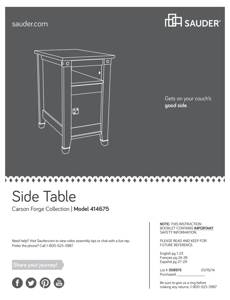
Need help? Visit Sauder.com to view video assembly tips or chat with a live rep.
Prefer the phone? Call 1-800-523-3987.
Share your journey!
sauder.com
NOTE: THIS INSTRUCTION
BOOKLET CONTAINS IMPORTANT
SAFETY INFORMATION.
PLEASE READ AND KEEP FOR
FUTURE REFERENCE.
English pg 1-22
Français pg 23-25
Español pg 26-28
Lot # 397871 12/07/16
Purchased: __________________
Be sure to give us a ring before
making any returns. 1-800-523-3987
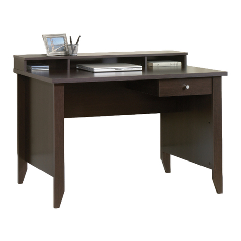
Computer Desk
Model 402375
Sit and surf.
Table of Contents Assembly Tools Required
Part Identification
Hardware Identification
Assembly Steps
Français
Español
Safety
Warranty
No. 2 Phillips Screwdriver
Tip Shown Actual Size
2-3
4-5
6-22
23-25
26-28
29-30
31
Hammer
Not actual size
Skip the power trip.
This time.
A2 RIGHT END (1)
B LEFT END (1)
C2 RIGHT UPRIGHT (1)
D2 LEFT UPRIGHT (1)
E3 TOP (1)
F2 MODESTY PANEL (1)
G2 RIGHT BOTTOM (1)
H LEFT BOTTOM (1)
I RIGHT BACK (1)
J LEFT BACK (1)
K ADJUSTABLE SHELF (1)
L KEYBOARD SHELF (1)
M DOOR (1)
N LARGE DRAWER FRONT (1)
R SMALL DRAWER FRONT (1)
V2 RIGHT BASE (1)
W LEFT BASE (1)
D44 SMALL DRAWER RIGHT SIDE (1)
D45 SMALL DRAWER LEFT SIDE (1)
D78 LARGE DRAWER BACK (1)
D86 SMALL DRAWER BACK (1)
D260 LARGE DRAWER RIGHT SIDE (1)
D263 LARGE DRAWER LEFT SIDE (1)
D707 LARGE DRAWER BOTTOM (1)
D716 SMALL DRAWER BOTTOM (1)
Now you know
our ABCs.
Part Identification
åWhile not all parts are labeled, some of the parts will have a label or an inked letter on the edge
to help distinguish similar parts from each other. Use this part identification to help identify similar parts.
Tape Measure
402375 www.sauder.com/servicesPage 2
Part Identification
A2
B
C2
D2
E3
F2
G2
H
I
J
K
L
M
N
R
V2
W
12-1/2"
12-1/2"
D260
D86
D707
D716
D78
D44
D45
D263
402375www.sauder.com/services Page 3
Hardware Identification
åScrews are shown actual size. You may receive extra hardware with your unit.
35DA CABINET RIGHT - 1 35DB CABINET LEFT - 1 35DC DRAWER RIGHT - 1 35DD DRAWER LEFT - 1
35AW CABINET RIGHT - 1 35AZ DRAWER LEFT - 1
35AY DRAWER RIGHT - 1
35AX CABINET LEFT - 1
45BA CABINET RIGHT - 1 45BD DRAWER LEFT - 1
45BC DRAWER RIGHT - 1
45BB CABINET LEFT - 1
FILE ROD - 2
KK ANGLE BRACKET - 6
LL
CORD CLIP - 1
OO
HIDDEN CAM - 16
MM2 CAM DOWEL - 16
NN2
402375 www.sauder.com/servicesPage 4
FILE GLIDE - 2
15B
Hardware Identification
åScrews are shown actual size. You may receive extra hardware with your unit.
BACKPLATE - 3
RR PULL - 3
SS LARGE DRAWER
FRONT BRACKET - 2
TT
FELT DISC CARD - 1
XX
METAL PIN - 4
YY RUBBER SLEEVE - 4
ZZ BLACK 1-7/8" FLAT HEAD SCREW - 4
AAA
BROWN 1" FLAT HEAD SCREW - 4
BBB BLACK 9/16" LARGE HEAD SCREW - 20
DDD
BLACK 1/2" FLAT HEAD SCREW - 4
EEE GOLD 5/16" FLAT HEAD SCREW - 20
GGG
NAIL - 29
HHH GOLD 1" MACHINE SCREW - 3
III
HINGE - 2
QQ
402375www.sauder.com/services Page 5
GROMMET - 1
7P GROMMET CAP- 1
8P
30S BLACK 1-9/16" FLAT HEAD SCREW - 8
SMALL DRAWER
FRONT BRACKET - 1
UU
Step 1 Look for this icon. It means a
video assembly tip is available at
www.sauder.com/services/tips
å Assemble your unit on a carpeted floor or on the empty
carton to avoid scratching your unit or the floor.
å Push sixteen HIDDEN CAMS (MM2) into the ENDS (A2
and B), UPRIGHTS (C2 and D2), and BOTTOMS (G2 and H).
Then, insert the metal end of a CAM DOWEL (NN2) into each
HIDDEN CAM.
A2
B
C2
D2
G2
H
Insert the metal end of the CAM
DOWEL into the HIDDEN CAM.
Arrow
Do not tighten the HIDDEN CAMS in this step.
Arrow
(16 used)
MM2
NN2
402375 www.sauder.com/servicesPage 6
Scan this QR code or go to this address:
http://qr.sauder.com/?ID=1660
to watch a video on how to assemble your unit.
å Fasten the CABINET RIGHTS (35AW, 35DA, and 45BA)
and CABINET LEFTS (35AX, 35DB and 45BB) to the
RIGHT END (A2) and UPRIGHTS (C2 and D2). Use twelve
GOLD 5/16" FLAT HEAD SCREWS (GGG).
Step 2
402375www.sauder.com/services Page 7
Remember:
Righty tighty.
Lefty loosey.
A2
D2
C2
Roller end
Roller end
Roller end
GOLD 5/16" FLAT HEAD SCREW
(12 used in this step)
GGG
35DA
35DA
35DB
35DB
45BB
45BB
45BA
45BA
Roller end
å Fasten the ENDS (A2 and B) and UPRIGHTS (C2 and D2) to
the BOTTOMS (G2 and H). Tighten eight HIDDEN CAMS.
Step 3
402375 www.sauder.com/servicesPage 8
Start Tighten
Arrow
Minimum
190 degrees
Caution
Risk of damage or
injury. HIDDEN CAMS
must be completely
tightened. HIDDEN
CAMS that are not
completely tightened
may loosen, and parts
may separate. To
completely tighten:
Arrow
Maximum
210 degrees
A2
D2
C2
BH
G2
Roller end
Roller end
This hole must be here.
Surface with
HIDDEN CAMS
Surface with
HIDDEN CAMS
Surface with
HIDDEN CAMS
Surface without
HIDDEN CAMS
Surface without
HIDDEN CAMS
Surface with
HIDDEN CAMS
Do not stand the unit upright without the
BACK fastened. The unit may collapse.
Caution
å Fasten six ANGLE BRACKETS (LL) to the ENDS (A2 and B),
UPRIGHTS (C2 and D2), and BOTTOMS (G2 and H). Use six
BLACK 9/16" LARGE HEAD SCREWS (DDD).
å NOTE: Be sure the edges of the ANGLE BRACKETS are even
with the edges of the ENDS, UPRIGHTS, and BOTTOMS.
å Fasten the BASES (V2 and W) to the ENDS (A2 and B),
UPRIGHTS (C2 and D2), and BOTTOMS (G2 and H). Use six
BLACK 9/16" LARGE HEAD SCREWS (DDD).
Step 4
402375www.sauder.com/services Page 9
A2
C2 G2
D2
BH
W
V2
LL
LL
LL
BLACK 9/16" LARGE HEAD SCREW
(12 used in this step)
DDD
å Make equal margins along all four edges of the BACKS (I
and J). Push on opposite corners of your unit if needed to
make it "square".
å Fasten the BACKS (I and J) to your unit using the NAILS (HHH).
å NOTE: Be sure to tap NAILS into the holes that line up over
the BOTTOMS (G2 and H).
Step 5
402375 www.sauder.com/servicesPage 10
Finished
surface
Finished
surface
G2
H
J
I
These edges must be even.
These holes must line up
over the BOTTOM (H).
These holes must line up
over the BOTTOM (G2).
NAIL
(29 used in this step)
HHH
Do not stand the unit upright without the
BACK fastened. The unit may collapse.
Caution
å Fasten the ENDS (A2 and B) and UPRIGHTS (C2 and D2) to the
TOP (E3). Tighten eight HIDDEN CAMS.
å Fasten the MODESTY PANEL (F2) to the UPRIGHTS (C2 and D2).
Use four BLACK 1-7/8" FLAT HEAD SCREWS (AAA).
Step 6
402375www.sauder.com/services Page 11
Arrow
Minimum
190 degrees
Maximum
210 degrees
A2
C2
E3
F2
D2 B
This hole must be here.
BLACK 1-7/8" FLAT HEAD SCREW
(4 used for the MODESTY PANEL)
AAA
Meet Part (E3). This component has
been engineered to be lighter, stronger,
faster… well ok. Not technically faster. But
definitely makes for a sturdier Computer
Desk that’s easier to assemble and
friendlier to the environment.
å Fasten the DRAWER RIGHT (35AY) and DRAWER LEFT (35AZ)
to the KEYBOARD SHELF (L). Use four BROWN 1" FLAT
HEAD SCREWS (BBB).
å Turn the CORD CLIP (OO) into the KEYBOARD SHELF (L).
å NOTE: The CORD CLIP is used to hold your keyboard cord
against the KEYBOARD SHELF.
Step 7
402375 www.sauder.com/servicesPage 12
L
Finished surface
OO
Roller end
Roller end
Finished edge
BROWN 1" FLAT HEAD SCREW
(4 used in this step)
BBB
å Carefully stand your unit upright.
å To insert the KEYBOARD SHELF (L) into your unit, tip the
front of the KEYBOARD SHELF down and drop the rollers
on the KEYBOARD SHELF behind the rollers on the unit.
Lift the front of the KEYBOARD SHELF up and slide it into
the unit.
Step 8
402375www.sauder.com/services Page 13
Pro Tip: Lift with your
legs. And, you know,
your arms.
L
å Fasten two HINGES (QQ) to the DOOR (M). Use four
BLACK 1/2" FLAT HEAD SCREWS (EEE).
Step 9
402375 www.sauder.com/servicesPage 14
QQ
BLACK 1/2" FLAT HEAD SCREW
(4 used in this step)
EEE
M
Step 10
402375www.sauder.com/services Page 15
B
M
XX
XX
RR +SS
å Before fastening the DOOR to your unit, be sure the
mounting screw is against the stops as shown in the right
diagram. If it isn't, loosen the mounting screw to slide it
against the stops. Then tighten the mounting screw.
å Fasten the DOOR (M) to the LEFT END (B) as shown in the
lower diagram. Use the screws in the HINGES. You should
start each SCREW a few turns before completely tightening
any of them.
å Fasten a BACKPLATE (RR) and PULL (SS) to the DOOR (M).
Use a GOLD 1" MACHINE SCREW (III).
å Peel the FELT DISC from the FELT DISC CARD (XX). Stick a
FELT DISC on the DOOR where it comes in contact with
the UPRIGHT (D2).
å See the next step for DOOR adjustments.
Mounting
screw
Stop
Hinge
GOLD 1" MACHINE SCREW
(1 used in this step)
III
D2
Step 11
402375 www.sauder.com/servicesPage 16
å Refer to the enlarged diagram to identify the parts on
the HINGES.
å The DOORS may need some adjustments. Follow the text below
to make needed adjustments.
å DOOR ADJUSTMENTS:
To adjust the DOORS from side to side (horizontal), turn the
adjusting screw in or out.
å To adjust the DOORS up and down (vertical), loosen both
vertical adjustment screws. Move the DOORS up or down to the
desired location. Tighten the screws after making adjustments.
å To adjust the DOORS in or out (depth), loosen the mounting
screw one turn and move the DOORS in or out, as needed.
Tighten the mounting screw after making adjustments.
Adjusting screw (horizontal) Mounting screw (depth)
(vertical adjustment)
Step 12
402375www.sauder.com/services Page 17
N
D707
BLACK 9/16" LARGE HEAD SCREW
(8 used for the DRAWER FRONTS)
DDD
D78
D260
D263
D260
D263
VIEW THE T-SLOT BOX VIDEO
1
23
UNFINISHED
å Pull the DRAWER FRONT BRACKETS (TT) apart and slide them into the grooves in the LARGE DRAWER SIDES (D260 and D263).
å NOTE: The DRAWER FRONT BRACKETS are marked "RH" and "LH" for easy identification.
å Fasten the LARGE DRAWER FRONT (N) to the DRAWER FRONT BRACKETS (TT). Use four BLACK 9/16" LARGE HEAD SCREWS (DDD).
å Slide the LARGE DRAWER BOTTOM (D707) into
the grooves in the LARGE DRAWER SIDES (D260
and D263) and LARGE DRAWER FRONT (N).
å Fasten the LARGE DRAWER BACK (D78) to the LARGE DRAWER SIDES (D260
and D263). Use four BLACK 1-9/16" FLAT HEAD SCREWS (30S).
å Repeat this step for the small drawer using the SMALL DRAWER
FRONT (R), SMALL DRAWER BACK (D86), SMALL DRAWER
SIDES (D44 and D45), SMALL DRAWER BOTTOM (D716), and
SMALL DRAWER FRONT BRACKETS (UU).
Be sure the DRAWER
BOTTOM inserts into the
DRAWER FRONT groove.
Be sure the
DRAWER
BOTTOM
inserts into
the DRAWER
BACK groove.
With the palm of
your hand, tap
the DRAWER
BOTTOM down
into the groove.
30S
Start each screw a few turns before
completely tightening any of them.
BLACK 1-9/16" FLAT HEAD SCREW
(8 used in this step)
D263
TT
Tap down with your
screwdriver and hammer.
15-1/2"
N
Groove
D260
D263
å Fasten the DRAWER RIGHT (45BC) and DRAWER LEFT (45BD)
to the DRAWER SIDES (D260 and D263). Use four GOLD
5/16" FLAT HEAD SCREWS (GGG) through holes #2 and #4.
å Repeat this step for the small drawer using holes #1 and #3 on
the DRAWER RIGHT (35DC) and DRAWER LEFT (35DD).
Step 13
402375 www.sauder.com/servicesPage 18
45BD
45BD
45BC
45BC
Roller end
Roller end
1
3
2
4
1
3
2
4
D260
D263
GOLD 5/16" FLAT HEAD SCREW
(8 used in this step)
GGG
(4 screws per drawer)
å Push a FILE GLIDE (15B) onto the LARGE DRAWER
RIGHT SIDE (D260).
å Slide the FILE RODS (KK) into the FILE GLIDE (15B) on
the LARGE DRAWER RIGHT SIDE.
å Slide another FILE GLIDE (15B) onto the other end of the
FILE RODS (KK), then press this FILE GLIDE over the
LARGE DRAWER LEFT SIDE (D263).
Step 14
402375www.sauder.com/services Page 19
KK
15B
15B
Insert the FILE RODS into the holes
of your choice in the FILE GLIDES,
depending on your file sizes.
D260
D263
å Push the RUBBER SLEEVES (ZZ) over the METAL PINS (YY).
Insert the METAL PINS into the hole locations of your choice in
the LEFT END (B) and LEFT UPRIGHT (D2). Set the ADJUSTABLE
SHELF (K) onto the METAL PINS.
å Insert the GROMMET (7P) and GROMMET CAP (8P) into the
hole in the TOP (E3).
Step 15
402375 www.sauder.com/servicesPage 20
8P
VV
E3
B
D2
K7P
YY
ZZ
Almost time to
celebrate! With a nap.

Other manuals for 402375

1

Other Sauder Indoor Furnishing manuals
Sauder Via Series 401446 User manual

Sauder

Sauder Via Series 401446 User manual

Sauder 414675 User manual

Sauder

Sauder 414675 User manual

Sauder Hammond 431249 User manual

Sauder

Sauder Hammond 431249 User manual

Sauder Jaclyn Smith Gatsby 415693 User manual

Sauder

Sauder Jaclyn Smith Gatsby 415693 User manual

Sauder HomePlus 422428 User manual

Sauder

Sauder HomePlus 422428 User manual

Sauder Cannery Bridge 415910 User manual

Sauder

Sauder Cannery Bridge 415910 User manual

Sauder Pallada Series 411843 User manual

Sauder

Sauder Pallada Series 411843 User manual

Sauder 412996 Installation guide

Sauder

Sauder 412996 Installation guide

Sauder Boulevard Cafe 420667 User manual

Sauder

Sauder Boulevard Cafe 420667 User manual

Sauder Embassy Point 414192 User manual

Sauder

Sauder Embassy Point 414192 User manual

Sauder Cannery Bridge 429556 User manual

Sauder

Sauder Cannery Bridge 429556 User manual

Sauder 413081 User manual

Sauder

Sauder 413081 User manual

Sauder Hammond 428246 User manual

Sauder

Sauder Hammond 428246 User manual

Sauder 416519 User manual

Sauder

Sauder 416519 User manual

Sauder Cannery Bridge 429515 User manual

Sauder

Sauder Cannery Bridge 429515 User manual

Sauder County 418529 User manual

Sauder

Sauder County 418529 User manual

Sauder Via 401447 User manual

Sauder

Sauder Via 401447 User manual

Sauder Parklane 419152 User manual

Sauder

Sauder Parklane 419152 User manual

Sauder Office Works Affirm 431916 User manual

Sauder

Sauder Office Works Affirm 431916 User manual

Sauder 413072 User manual

Sauder

Sauder 413072 User manual

Sauder Edge Water Series User manual

Sauder

Sauder Edge Water Series User manual

Sauder Briarbrook 430070 User manual

Sauder

Sauder Briarbrook 430070 User manual

Sauder Englewood 426908 User manual

Sauder

Sauder Englewood 426908 User manual

Sauder Harbor View 158002 User manual

Sauder

Sauder Harbor View 158002 User manual

Popular Indoor Furnishing manuals by other brands

ROOMS TO GO Ovis 60699 manual

ROOMS TO GO

ROOMS TO GO Ovis 60699 manual

Space Seating 829-R2C728P Assembly and operating instructions

Space Seating

Space Seating 829-R2C728P Assembly and operating instructions

Jysk KETTINGE quick start guide

Jysk

Jysk KETTINGE quick start guide

Style selections EDWARDS 36DC installation manual

Style selections

Style selections EDWARDS 36DC installation manual

Coaster 183452 Assembly instructions

Coaster

Coaster 183452 Assembly instructions

HAMPTON BAY FRS81094B-STL Use and care guide

HAMPTON BAY

HAMPTON BAY FRS81094B-STL Use and care guide

BDI Meriden 8127 Assembly instructions

BDI

BDI Meriden 8127 Assembly instructions

Exclusive Heritage BV-20060D-WMCG installation manual

Exclusive Heritage

Exclusive Heritage BV-20060D-WMCG installation manual

Walker Edison W58CSTBV2D Assembly instructions

Walker Edison

Walker Edison W58CSTBV2D Assembly instructions

Safavieh Furniture DTB1403 manual

Safavieh Furniture

Safavieh Furniture DTB1403 manual

Whalen WF36FVB manual

Whalen

Whalen WF36FVB manual

modway EEI-2266 quick start guide

modway

modway EEI-2266 quick start guide

Seconique MONACO Assembly instructions

Seconique

Seconique MONACO Assembly instructions

modway Marchesa EEI-5015 Assembly instructions

modway

modway Marchesa EEI-5015 Assembly instructions

ASH & EMBER Grade A Teak 25" Barstool user manual

ASH & EMBER

ASH & EMBER Grade A Teak 25" Barstool user manual

Muller TB 224 Assembly instruction

Muller

Muller TB 224 Assembly instruction

RTA Products TECHNI MOBILI RTA-80X5 Assembly instructions

RTA Products

RTA Products TECHNI MOBILI RTA-80X5 Assembly instructions

TOV Gala Assembly instructions

TOV

TOV Gala Assembly instructions

manuals.online logo
manuals.online logoBrands
  • About & Mission
  • Contact us
  • Privacy Policy
  • Terms and Conditions

Copyright 2025 Manuals.Online. All Rights Reserved.