manuals.online logo
Brands
  1. Home
  2. •
  3. Brands
  4. •
  5. Sauder
  6. •
  7. Indoor Furnishing
  8. •
  9. Sauder Shoal Creek 412093 User manual

Sauder Shoal Creek 412093 User manual

Need help? Visit Sauder.com to view video assembly tips or chat with a live rep.
Prefer the phone? Call 1-800-523-3987.
Share your journey!
sauder.com
NOTE: THIS INSTRUCTION
BOOKLET CONTAINS IMPORTANT
SAFETY INFORMATION.
PLEASE READ AND KEEP FOR
FUTURE REFERENCE.
English pg 1-20
Français pg 21-23
Español pg 24-26
Lot # 385515 11/05/15
Purchased: __________________
Be sure to give us a ring before
making any returns. 1-800-523-3987
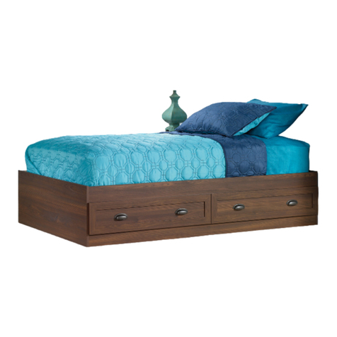
Mates Bed
Shoal Creek Collection | Model 412093
You won't just fall in
love with it. You'll fall
asleep in it.
Table of Contents Assembly Tools Required
Hammer
Not actual size
No. 2 Phillips Screwdriver
Tip Shown Actual Size
Skip the power trip.
This time.
Part Identification
Hardware Identification
Assembly Steps
Français
Español
Warranty
2-3
4
5-20
21-23
24-26
27
412093 www.sauder.com/servicesPage 2
Now you know
our ABCs.
Part Identification
åWhile not all parts are labeled, some of the parts will have a label or an inked letter on the edge
to help distinguish similar parts from each other. Use this part identification to help identify similar parts.
A2 BOTTOM (2)
B3 BOTTOM SUPPORT (2)
B30 DRAWER BOTTOM (2)
C3 UPRIGHT (1)
D212 RIGHT DRAWER SIDE (2)
D213 LEFT DRAWER SIDE (2)
D476 DRAWER BACK (2)
D477 DRAWER DIVIDER (2)
E3 END (2)
G3 UPPER FRONT PANEL (1)
H3 LOWER FRONT PANEL (1)
I3 BACK PANEL (1)
J2 SMALL SLAT (4)
M65 DRAWER BRACE (2)
S RIGHT DRAWER FRONT (1)
T LEFT DRAWER FRONT (1)
Part Identification
412093www.sauder.com/services Page 3
A2
A2
B3
B3
C3
G3
B30
B30
S
T
H3
D476 D477
D477
D476
E3
E3
I3
D212
D212
D213
D213
J2
J2 J2
J2
M65
M65
Hardware Identification
åScrews are shown actual size. You may receive extra hardware with your unit.
412093 www.sauder.com/servicesPage 4
40CB CABINET LEFT - 2
40CA CABINET RIGHT - 2 40CC DRAWER RIGHT - 2 40CD DRAWER LEFT - 2
30S BLACK 1-9/16" FLAT HEAD SCREW - 10 BROWN 1-5/8" FLAT HEAD SCREW - 10
55S
BLACK 9/16" LARGE HEAD SCREW - 10
1S
SUPPORT PIN - 12
4R
SILVER 1-1/8" FLAT HEAD SCREW - 20
10S 15S SILVER 5/8" MACHINE SCREW - 8
SUPPORT BRACKET - 1
11B
3S GOLD 5/16" FLAT HEAD SCREW - 16
WOOD DOWEL - 11
15F
HIDDEN CAM - 14
1F CAM DOWEL - 14
2F
GLUE - 1
54M
PULL- 4
7K
DRAWER FRONT BRACKET - 2
8G
Step 1 Look for this icon. It means a
video assembly tip is available at
www.sauder.com/services/tips
å Assemble your unit on a carpeted floor or on the empty
carton to avoid scratching your unit or the floor.
å Push fourteen HIDDEN CAMS (1F) into the UPRIGHT (C3),
DRAWER BRACES (M65), and PANELS (G3, H3, and I3).
Then, insert the metal end of a CAM DOWEL (2F) into
each HIDDEN CAM.
412093www.sauder.com/services Page 5
(14 used)
Arrow
1F
2F
Do not tighten the HIDDEN CAMS in this step.
Insert the metal end of the CAM
DOWEL into the HIDDEN CAM.
Arrow
I3
G3
C3
H3
M65
M65
Scan this QR code or go to this address:
http://qr.sauder.com/?ID=1719
to watch a video on how to assemble your unit.
å Fasten a CABINET RIGHT (40CA) and a CABINET
LEFT (40CB) to the ENDS (E3). Use four GOLD 5/16"
FLAT HEAD SCREWS (3S) through holes #1 and #3.
å NOTE: After you attach the CABINET RAILS, the ENDS
will be labeled RIGHT END and LEFT END.
Step 2
412093 www.sauder.com/servicesPage 6
E3
E3
Remember:
Righty tighty.
Lefty loosey.
GOLD 5/16" FLAT HEAD SCREW
(4 used in this step)
3S
Roller end
Roller end
1
2
34
1
2
3
4
This END (E3) will now be
called the RIGHT END (E3).
This END (E3) will now be
called the LEFT END (E3).
Rounded edge
Rounded edge
å Fasten the remaining CABINET RIGHT (40CA) and
CABINET LEFT (40CB) to the UPRIGHT (C3). Use
four GOLD 5/16" FLAT HEAD SCREWS (3S) through
holes #1 and #3.
Step 3
412093www.sauder.com/services Page 7
C3
Surface with HIDDEN CAMS
GOLD 5/16" FLAT HEAD SCREW
(4 used in this step)
3S
Roller end
Roller end
1
2
3
4
1
2
3
4
Finished edge
Step 4
412093 www.sauder.com/servicesPage 8
å Fasten the BOTTOM SUPPORTS (B3) to the ENDS (E3).
Use eight SILVER 1-1/8" FLAT HEAD SCREWS (10S).
å Fasten the SMALL SLATS (J2) to the BACK PANEL (I3)
and UPPER FRONT PANEL (G3). Use twelve SILVER 1-1/8"
FLAT HEAD SCREWS (10S).
å NOTE: Use the exact holes shown.
Left End Right End
B3
B3
E3
E3
I3
G3
SILVER 1-1/8" FLAT HEAD SCREW
(20 used in this step)
10S
Edge with no holes
If the BOTTOM SUPPORTS (B3) or
SMALL SLATS (J2) have a finished
surface, it should be facing up.
J2
J2
J2
J2
Edge with no holes
Edge with no holes
Finished edge
Finished edge
å First, fill the holes in a short edge of the BACK PANEL (I3) 1/4 to
1/2 full with GLUE (54M). Then, insert two WOOD DOWELS (15F)
into the holes. Wipe away the excess GLUE.
å Next, fill the holes in the other short edge of the BACK PANEL (I3)
1/4 to 1/2 full with GLUE. Then, insert two WOOD DOWELS (15F)
into these holes. Wipe away the excess GLUE.
å Now, fill the holes in the RIGHT END (E3) 1/4 to 1/2 full with GLUE.
Be sure to fill the second and fourth holes from the rounded edge
as shown.
å Fasten the RIGHT END (E3) to the BACK PANEL (I3). Tighten two
HIDDEN CAMS.
å NOTE: Be sure the WOOD DOWELS in the BACK PANEL insert
into the holes in the RIGHT END. Wipe away the excess glue.
Step 5
412093www.sauder.com/services Page 9
Start Tighten
Arrow
Minimum
190 degrees
Caution
Risk of damage or
injury. HIDDEN CAMS
must be completely
tightened. HIDDEN
CAMS that are not
completely tightened
may loosen, and parts
may separate. To
completely tighten:
Arrow
Maximum
210 degrees
E3
I3
Right End
Rounded edge
Roller end
Fill the holes 1/4 to 1/2 full with GLUE.
Inspect the parts thoroughly before
assembling. Disassembly of glued
parts is extremely dicult.
Caution
!
54M
15F
15F
Surface with HIDDEN CAMS
Step 6
412093 www.sauder.com/servicesPage 10
Arrow
Minimum
190 degrees
Maximum
210 degrees
C3
I3
Surface with
HIDDEN CAMS
These holes
must be here.
Roller end
15F
15F
å First, fill the hole in the short edge of the UPRIGHT (C3) 1/4 to 1/2
full with GLUE (54M). Then, insert a WOOD DOWEL (15F) into the
hole. Wipe away the excess GLUE.
å Next, fill the two holes in the other short edge of the UPRIGHT (C3)
1/4 to 1/2 full with GLUE. Then, insert two WOOD DOWELS
(15F)
into these holes. Wipe away the excess GLUE.
å Now, fill the holes in the BACK PANEL (I3) 1/4 to 1/2 full with
GLUE. Be sure to fill the second and fourth holes from the top
edge as shown.
å Fasten the UPRIGHT (C3) to the BACK PANEL (I3). Tighten two
HIDDEN CAMS.
å NOTE: Be sure the WOOD DOWELS in the UPRIGHT insert into
the holes in the BACK PANEL. Wipe away the excess glue.
54M
Fill the holes 1/4 to 1/2 full with GLUE.
Inspect the parts thoroughly before
assembling. Disassembly of glued
parts is extremely dicult.
Caution
!
Step 7
412093www.sauder.com/services Page 11
Arrow
Minimum
190 degrees
Maximum
210 degrees
H3
G3
E3
C3
Surface without HIDDEN CAMS
Right End
15F
15F
54M
Fill the holes 1/4 to 1/2 full with GLUE.
Inspect the parts thoroughly before
assembling. Disassembly of glued
parts is extremely dicult.
Caution
!
Rounded edge
å First, fill the holes in the short edges of the FRONT PANELS (G3 and H3)
1/4 to 1/2 full with GLUE (54M). Then, insert two WOOD DOWELS (15F)
into the holes. Wipe away the excess GLUE.
å Fill the hole in the middle of the LOWER FRONT PANEL (H3) 1/4 to 1/2
with GLUE. Be sure to fill the hole closest to the unfinished edge.
å Now, fill the holes in the RIGHT END (E3) 1/4 to 1/2 full with GLUE. Be sure
to fill the second and fourth holes from the rounded edge as shown.
å Fasten the FRONT PANELS (G3 and H3) to the RIGHT END (E3) and
UPRIGHT (C3). Tighten four HIDDEN CAMS.
å NOTE: Be sure the WOOD DOWELS in the FRONT PANELS insert into the
holes in the RIGHT END and the WOOD DOWEL in the UPRIGHT inserts
into the LOWER FRONT PANEL. Wipe away the excess glue.
å Lastly, fill the holes in the opposite short edges of the FRONT
PANELS (G3 and H3) 1/4 to 1/2 full with GLUE. Then, insert
two WOOD DOWELS (15F) into these holes. Wipe
away the excess GLUE.
Unfinished edge
Finished edge
å Fill the holes in the LEFT END (E3) 1/4 to 1/2 full with GLUE (54M).
Be sure to fill the second and fourth holes from the rounded edge
as shown in the lower diagram.
å Fasten the LEFT END (E3) to the FRONT PANELS (G3 and H3)
and BACK PANEL (I3). Tighten four HIDDEN CAMS.
å NOTE: Be sure the WOOD DOWELS in the PANELS insert into the
holes in the LEFT END. Wipe away the excess glue.
Step 8
412093 www.sauder.com/servicesPage 12
Arrow
Minimum
190 degrees
Maximum
210 degrees
E3
E3
G3
H3
I3
Left End
Rounded edge
Rounded edge
Roller end
Roller end
54M
Fill the holes 1/4 to 1/2 full with GLUE.
Inspect the parts thoroughly before
assembling. Disassembly of glued
parts is extremely dicult.
Caution
!
å NOTE: This step is a dierent view looking at the bed from
the back side.
å Fasten the SUPPORT BRACKET (11B) to the UPRIGHT (C3).
Use two BLACK 9/16" LARGE HEAD SCREWS (1S).
Step 9
412093www.sauder.com/services Page 13
VIEW FROM THE BACK SIDE OF THE BED
11B
C3
BLACK 9/16" LARGE HEAD SCREW
(2 used in this step)
1S
11B
Don't worry. It isn't
Rome. This can be built
in a day.
Step 10
412093 www.sauder.com/servicesPage 14
å Using your hammer, gently tap twelve SUPPORT PINS (4R)
into the center holes in the DRAWER FRONTS (S and T)
and DRAWER BACKS (D476).
4R
S
T
(12 used)
D476
D476
Step 11
412093www.sauder.com/services Page 15
1
3
2
4
Unfinished surface
å Pull the DRAWER FRONT BRACKETS (8G) apart and slide them
into the grooves in the DRAWER SIDES (D212 and D213). You may
need to gently tap them in with a hammer.
å NOTE: The DRAWER FRONT BRACKETS are marked "RH" and
"LH" for easy identification.
å Fasten the LEFT DRAWER FRONT (T) to the DRAWER FRONT
BRACKETS (8G). Use four BLACK 9/16" LARGE HEAD SCREWS (1S).
å Slide the DRAWER BOTTOM (B30) into the
grooves in the DRAWER SIDES (D212 and D213)
and DRAWER FRONT (T).
å Fasten the DRAWER BRACE (M65) to the DRAWER
FRONT (T). Tighten one HIDDEN CAM.
å Fasten the DRAWER BACK (D476) to the DRAWER
SIDES (D212 and D213) and DRAWER BRACE (M65).
Use five BLACK 1-9/16" FLAT HEAD SCREWS (30S).
Repeat this step for the other drawer.
D212
B30
D213
D212
D476
D213
D212
D213
T
T
T
Be sure the DRAWER
BOTTOM inserts into the
DRAWER FRONT groove.
Be sure the
DRAWER
BOTTOM
inserts into
the DRAWER
BACK groove.
With the palm of your hand,
tap the DRAWER BOTTOM
down into the groove.
BLACK 9/16" LARGE HEAD SCREW
(8 used in this step)
1S
Start each screw a few turns before
completely tightening any of them.
BLACK 1-9/16" FLAT HEAD SCREW
(10 used in this step)
M65
M65
30S
8G
Arrow
Maximum
210 degrees
Minimum
190 degrees
Push down
Surface with
HIDDEN CAM
å Fasten the DRAWER RIGHT (40CC) to the RIGHT
DRAWER SIDE (D212) and the DRAWER LEFT (40CD) to
the LEFT DRAWER SIDE (D213). Use four GOLD 5/16"
FLAT HEAD SCREWS (3S) through holes #1 and #4.
å Repeat this step for the other drawer.
Step 12
412093 www.sauder.com/servicesPage 16
D212
D213
1
2
3
4
Roller end
Roller end
1
2
3
4
GOLD 5/16" FLAT HEAD SCREW
(8 used in this step)
3S
(4 screws per drawer)
å Slide a DRAWER DIVIDER (D477) into the SUPPORT PINS on
the LEFT DRAWER FRONT (T) and DRAWER BACK (D476).
å Fasten two PULLS (7K) to the LEFT DRAWER FRONT (T).
Use four SILVER 5/8" MACHINE SCREWS (15S).
å Repeat this step for the other drawer.
Step 13
412093www.sauder.com/services Page 17
SILVER 5/8" MACHINE SCREW
(8 used for the PULLS)
15S
T
Finished edge
D477
D476
7K
7K
Want options? Customize
your item with add-on
hardware kits available
on sauder.com.
å If you purchased the 412091 Headboard, assemble that
unit now. The Headboard attachment will be shown in the
412091 Headboard instruction book.
å NOTE: The diagrams are shown below for the 412091
Headboard on the left or right of your Mates Bed.
Step 14
412093 www.sauder.com/servicesPage 18
412091 HEADBOARD on the right
412091 HEADBOARD on the left
å Fasten the BOTTOMS (A2) to the BOTTOM SUPPORTS (B3),
UPRIGHT (C3), and SMALL SLATS (J2). Use ten BROWN
1-5/8" FLAT HEAD SCREWS (55S).
Step 15
412093www.sauder.com/services Page 19
A2
A2
C3
B3
B3
Hey! It's starting to look
like something!
J2
J2
BROWN 1-5/8" FLAT HEAD SCREW
(10 used in this step)
55S
å To insert the drawers into your unit, tip the front of the drawer down and drop the rollers on the
drawer behind the rollers on the unit. Lift the front of the drawer up and slide it into the unit.
å To make adjustments to the drawer, loosen the SCREWS in the DRAWER FRONT BRACKETS,
make needed adjustments, and tighten the SCREWS.
å This completes assembly. Clean with your favorite furniture polish or a damp cloth. Wipe dry.
Step 16
412093 www.sauder.com/servicesPage 20
And to celebrate, why not share your success story?
30 lbs.
total
30 lbs.
total
S
T
Place the roller on the SLIDE
behing the roller on the RAIL.

Other Sauder Indoor Furnishing manuals
Sauder 411802 User manual

Sauder

Sauder 411802 User manual

Sauder Worksense BERGEN CIRCLE 426459 User manual

Sauder

Sauder Worksense BERGEN CIRCLE 426459 User manual

Sauder 419198 User manual

Sauder

Sauder 419198 User manual

Sauder Cottage Road 416039 User manual

Sauder

Sauder Cottage Road 416039 User manual

Sauder Studio RTA 408531 User manual

Sauder

Sauder Studio RTA 408531 User manual

Sauder 423032 User manual

Sauder

Sauder 423032 User manual

Sauder Nova Loft 425211 User manual

Sauder

Sauder Nova Loft 425211 User manual

Sauder Carson Forge 412920 User manual

Sauder

Sauder Carson Forge 412920 User manual

Sauder Clifford Place 429508 User manual

Sauder

Sauder Clifford Place 429508 User manual

Sauder Steel River 427855 User manual

Sauder

Sauder Steel River 427855 User manual

Sauder Englewood 426908 User manual

Sauder

Sauder Englewood 426908 User manual

Sauder Pinwheel 421888 User manual

Sauder

Sauder Pinwheel 421888 User manual

Sauder Barrister Lane 414723 User manual

Sauder

Sauder Barrister Lane 414723 User manual

Sauder 415421 User manual

Sauder

Sauder 415421 User manual

Sauder 415543 User manual

Sauder

Sauder 415543 User manual

Sauder Corner Entertainment Credenza 403818 User manual

Sauder

Sauder Corner Entertainment Credenza 403818 User manual

Sauder Harbor View 401328 User manual

Sauder

Sauder Harbor View 401328 User manual

Sauder Clifford Place 421113 User manual

Sauder

Sauder Clifford Place 421113 User manual

Sauder Palladia Lateral File User manual

Sauder

Sauder Palladia Lateral File User manual

Sauder Summit Station 425014 User manual

Sauder

Sauder Summit Station 425014 User manual

Sauder Manhattan Gate 429256 User manual

Sauder

Sauder Manhattan Gate 429256 User manual

Sauder Shoal Creek Series User manual

Sauder

Sauder Shoal Creek Series User manual

Sauder Palladia 411861 User manual

Sauder

Sauder Palladia 411861 User manual

Sauder 414289 User manual

Sauder

Sauder 414289 User manual

Popular Indoor Furnishing manuals by other brands

Cooper Lighting Portfolio M6235T Specification sheet

Cooper Lighting

Cooper Lighting Portfolio M6235T Specification sheet

Whittier Wood Furniture McKenzie Cal-King 1333AFGAC Assembly instructions

Whittier Wood Furniture

Whittier Wood Furniture McKenzie Cal-King 1333AFGAC Assembly instructions

Coaster 736178 Assembly instructions

Coaster

Coaster 736178 Assembly instructions

BRIO Kitchen Combo 31360 manual

BRIO

BRIO Kitchen Combo 31360 manual

Household Essentials 18410-1 instructions

Household Essentials

Household Essentials 18410-1 instructions

Rapidline AM100 Assembly instructions

Rapidline

Rapidline AM100 Assembly instructions

for Living Beacon Hill Space Saver H15-1835 Assembly instructions

for Living

for Living Beacon Hill Space Saver H15-1835 Assembly instructions

Furniture of America CM7150Q Assembly instructions

Furniture of America

Furniture of America CM7150Q Assembly instructions

Santos Andirá Invicta 225466 Assembling instructions

Santos Andirá

Santos Andirá Invicta 225466 Assembling instructions

Furinno FNCL-33002 Assembly instruction

Furinno

Furinno FNCL-33002 Assembly instruction

Costway CB10119 user manual

Costway

Costway CB10119 user manual

indusigns Tabo installation manual

indusigns

indusigns Tabo installation manual

Varier Kokon Club Assembly instructions

Varier

Varier Kokon Club Assembly instructions

Otto REGAL Assembly instructions

Otto

Otto REGAL Assembly instructions

Gami SANDRO J76 manual

Gami

Gami SANDRO J76 manual

Monarch Specialties I 3412 Assembly instructions

Monarch Specialties

Monarch Specialties I 3412 Assembly instructions

MAISONS DU MONDE SASHA 205968 manual

MAISONS DU MONDE

MAISONS DU MONDE SASHA 205968 manual

Broyhill LEGACY THORNWOOD GB21-801 Assembly instructions

Broyhill

Broyhill LEGACY THORNWOOD GB21-801 Assembly instructions

manuals.online logo
manuals.online logoBrands
  • About & Mission
  • Contact us
  • Privacy Policy
  • Terms and Conditions

Copyright 2025 Manuals.Online. All Rights Reserved.