manuals.online logo
Brands
  1. Home
  2. •
  3. Brands
  4. •
  5. SDC
  6. •
  7. Door Lock
  8. •
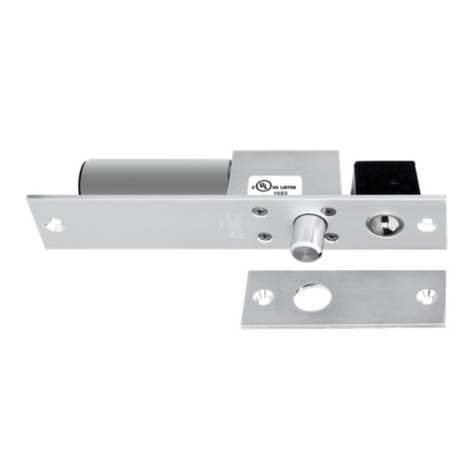
  9. SDC TEMPLATE 180 SERIES User manual

SDC TEMPLATE 180 SERIES User manual

This manual suits for next models

2

Other SDC Door Lock manuals

SDC PRO Series User manual

SDC

SDC PRO Series User manual

SDC Z7700 Series User manual

SDC

SDC Z7700 Series User manual

SDC E75 Series Operating instructions

SDC

SDC E75 Series Operating instructions

SDC 1511S User manual

SDC

SDC 1511S User manual

SDC Z7200R User manual

SDC

SDC Z7200R User manual

SDC EntryCheck 918 User manual

SDC

SDC EntryCheck 918 User manual

SDC E72 EntryCheck Troubleshooting guide

SDC

SDC E72 EntryCheck Troubleshooting guide

SDC 352 Narrow Line EMLock User manual

SDC

SDC 352 Narrow Line EMLock User manual

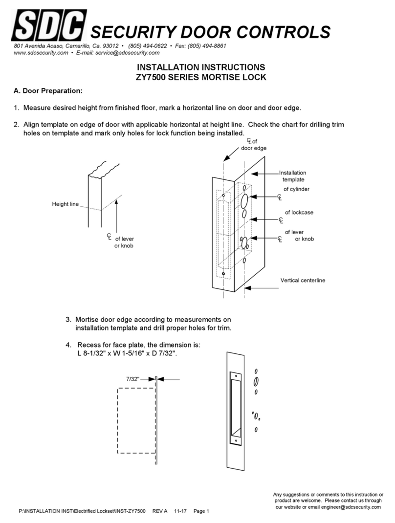
SDC Z7500 Series User manual

SDC

SDC Z7500 Series User manual

SDC Excel E1200 Series User manual

SDC

SDC Excel E1200 Series User manual

SDC ZA7200 Series User manual

SDC

SDC ZA7200 Series User manual

SDC E70PS Series Owner's manual

SDC

SDC E70PS Series Owner's manual

SDC Z7200 User manual

SDC

SDC Z7200 User manual

SDC SK-82 User manual

SDC

SDC SK-82 User manual

SDC S6800 Series Quick start guide

SDC

SDC S6800 Series Quick start guide

SDC Z7500 Series User manual

SDC

SDC Z7500 Series User manual

SDC FS23M Series User manual

SDC

SDC FS23M Series User manual

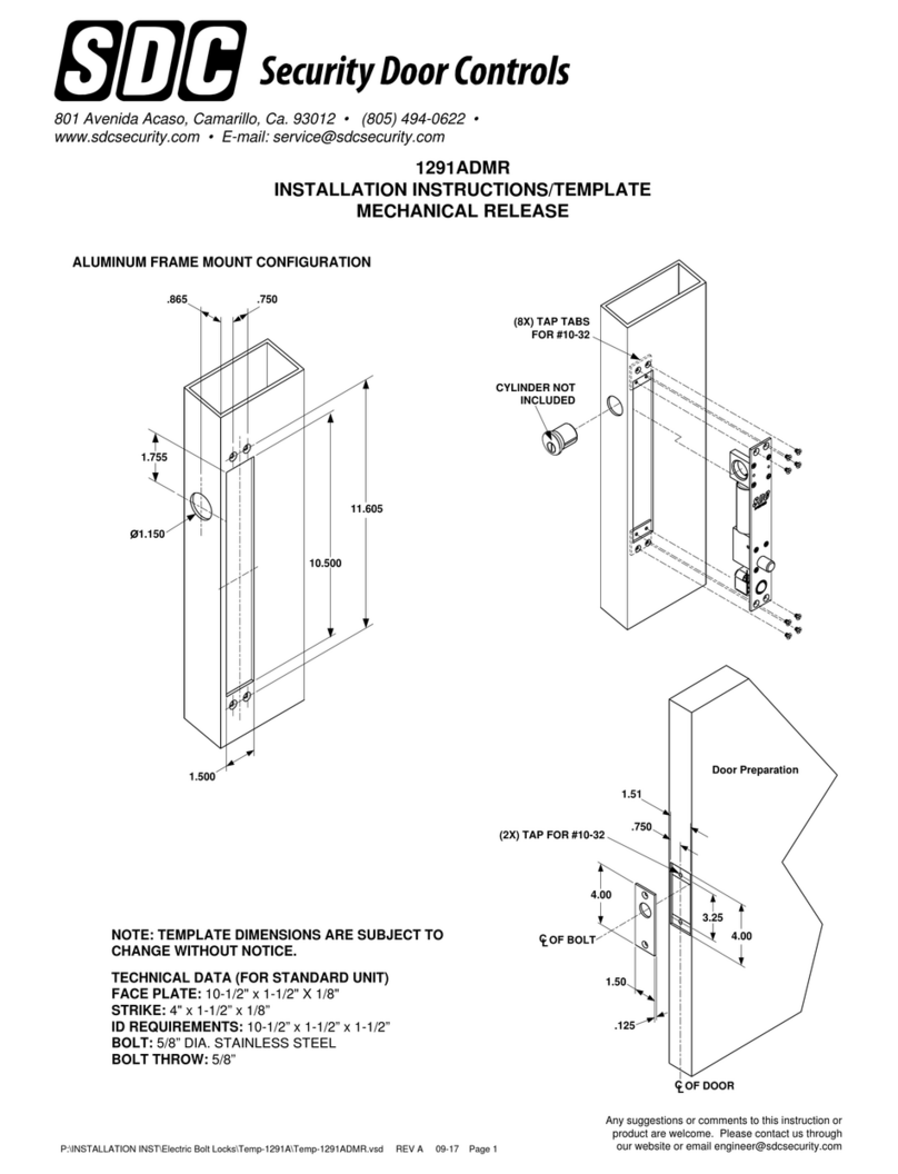
SDC Spacesaver 1091 ADMR User manual

SDC

SDC Spacesaver 1091 ADMR User manual

SDC S6300 Series User manual

SDC

SDC S6300 Series User manual

SDC E75 Series User manual

SDC

SDC E75 Series User manual
SDC Z7835 Series User manual

SDC

SDC Z7835 Series User manual

SDC Z7836 Series User manual

SDC

SDC Z7836 Series User manual

SDC 1190A Series User manual

SDC

SDC 1190A Series User manual
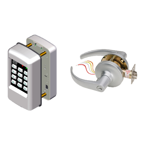
SDC PD2090A User manual

SDC

SDC PD2090A User manual

Popular Door Lock manuals by other brands

Dorma MUNDUS PREMIUM US 10 Mounting instruction

Dorma

Dorma MUNDUS PREMIUM US 10 Mounting instruction

Defiant LG600BRA4BGT Instructions for installation

Defiant

Defiant LG600BRA4BGT Instructions for installation

TRU-BOLT M1740024 manual

TRU-BOLT

TRU-BOLT M1740024 manual

Opera ARCA SLIDE installation instructions

Opera

Opera ARCA SLIDE installation instructions

tell CODELOCK CL5500 Series installation instructions

tell

tell CODELOCK CL5500 Series installation instructions

ABH LR6000 installation instructions

ABH

ABH LR6000 installation instructions

Assa Abloy effeff 827A-IP Mounting instructions

Assa Abloy

Assa Abloy effeff 827A-IP Mounting instructions

Iseo MA1A installation guide

Iseo

Iseo MA1A installation guide

ID Lock 150 user manual

ID Lock

ID Lock 150 user manual

Lockly ACCESS TOUCH PRO user manual

Lockly

Lockly ACCESS TOUCH PRO user manual

iLoq G50S user guide

iLoq

iLoq G50S user guide

ilco 452 Installation

ilco

ilco 452 Installation

Samsung shs-h705 user guide

Samsung

Samsung shs-h705 user guide

TRU-BOLT 08102017 user manual

TRU-BOLT

TRU-BOLT 08102017 user manual

CDVI 500-LADJ quick start guide

CDVI

CDVI 500-LADJ quick start guide

Igloohome Deadbolt 2S Metal Grey Installer/user guide

Igloohome

Igloohome Deadbolt 2S Metal Grey Installer/user guide

eSSL FL-300 user manual

eSSL

eSSL FL-300 user manual

Dorma MUNDUS PREMIUM GK 50 Mounting instruction

Dorma

Dorma MUNDUS PREMIUM GK 50 Mounting instruction

manuals.online logo
manuals.online logoBrands
  • About & Mission
  • Contact us
  • Privacy Policy
  • Terms and Conditions

Copyright 2025 Manuals.Online. All Rights Reserved.

1. Determine the appropriate mounting configuration for your application (Header mount or Top-jamb or Side-jamb
mount.
2. Determine the handing for your application.
3. Remove the lock housing cover. Based on the mounting information determined on steps 1 & 2 above, adjust
the Auto Relock Switch (ARS) in the bolt chamber bracket as described below.
3a. Remove the ARS insert and install the ARS switch as shown. Replace the plastic insert.
Any suggestions or comments to this instruction or
product are welcome. Please contact us through
our website or email [email protected]
P:\INSTALLATION INST\Electric Bolt Locks\TEMP-180-280\INST-180_280.vsd REV E 08-17 Page 1
INSTALLATION INSTRUCTIONS/TEMPLATE
180/280 SERIES ELECTRIC LOCKS
801 Avenida Acaso, Camarillo, Ca. 93012 • (805) 494-0622 •
www.sdcsecurity.com • E-mail: [email protected]
Header
Mount
Top-
Jamb
Side-
Jamb
DOOR
FRAME HEADER
LOCK
STRIKE
END VIEW
Header Mount
Outswing Door
FRAME HEADER
OR SIDE JAMB
LOCK
STRIKE
DOOR
Top or Side Jamb
Inswing or Sliding Door
EXTERIOR
Strike
Block
LHR RHR
Header Mount
Door
LOCK
Door
LOCK
LH
Door
Strike
Block
Lock
Top-jamb
RH
Door
Door
Strike
Block Lock
Side-jamb
LOCK
Mounting
Plate
ARS Cover
Insert Bolt
Chamber
Bracket
Perpendicular to
Mounting Plate Parallel to
Mounting Plate
MountingConfiguration Auto‐RelockSwitchOrientation
HeaderMounted‐LHRPerpendiculartothemountingplate
HeaderMounted‐RHRPerpendiculartothemountingplate
TopJamborSideJamb‐Swing(LHorRH) Perpendiculartothemountingplate
TopJamb‐SlidingtoLeft* Paralleltothemountingplate
TopJamb‐SlidingtoRight* Paralleltothemountingplate
*TobJambSlidingDoorrequiresapositivestop
5. Mark and drill as follows: Holes 1, 2, 3, and 4 for #10 sheet metal screws or 10-32 x 1/2 machine screws.
Hole 8 – 3/8" diameter for wire.
Block strike: Holes 5 and 6 or 12 and 13 for 1/4 - 20 machine screw.
6. Tap holes as required.
7. Mount lock and strike block.
8. Attach power leads as shown on Page 3. When bolt is thrown, check alignment of bolt and strike. There should
be no binding on the bolt. Leading part of strike block should be 1/8" away from the lock (1/8" is maximum
distance). If this is correct, tighten mounting screws.
9. Check lock operation for any last adjustments.
10. Re-install housing cover.
4. Configure the strike block assembly
(Choose 4a, 4b, or 4c):
Strike Block
ARS magnet
Strike Insert
w/ screws
Block Shim
(use as
needed)
4c. For Top Jamb (swing or slide) or Side Jamb
Strike hole
away from
magnet
This end
towards the
door
P:\INSTALLATION INST\Electric Bolt Locks\TEMP-180-280\INST-180_280.vsd REV E 08-17 Page 2
4b. For Header-mounted, LHR
Strike hole
away from
magnet
This end
towards the
door
4a. For Header-mounted, RHR
Strike hole
towards
magnet
This end
towards the
door
ELECTRICAL DATA:
Dual Voltage (180/280)
12VDC@ .9 Amp (max.)
24VDC@ .45 Amp (max.)
Continuous Duty
LOCK WIRING
180 Wiring: **AC Power requires
the PR-1000
RED (+)
BLU
BLK
WHT (-)
12VDC SOLENOID
CONFIGURATION
12VDC @
900mA (max)
RED (+)
BLK
BLU
WHT (-)
24VDC @
450mA (max)
24VDC SOLENOID
CONFIGURATION
280 Wiring:
Solenoid Voltage Configuration:
NOTE: The SDC PR-1000 Power Regulator module is included with the 180/280 bolt lock, and is required for optimal
solenoid lifespan. Installing the PR-1000 reduces the power consumption of the bolt locks after activation of the lock,
allowing for a heat reduction to the bolt lock.
PR-1000
VOLTAGE
REGULATOR
YEL/BLK (~)
YEL (~) or (+DC)
(-)
+
Access
Control or
Push Button
(N/C)
N/O
N/C
COM
AC
POWER
BLK (-DC)
RED (+)
WHT (-)
ORG
BLU
WHT/BLK
Not
Used
(~)
(~) DC
POWER
INPUT
Solenoid 180 ARS
(DOOR CLOSED)
YEL GRY
*See below for
solenoid wiring
PR-1000
VOLTAGE
REGULATOR
YEL/BLK (~)
YEL (~) or (+DC)
(-)
+
AC
POWER
BLK (-DC)
ORG
BLU
WHT/BLK
(~)
(~) DC
POWER
INPUT
ACCESS
CONTROL
(N/O)
N/O
N/C
COM
RED (+)
WHT (-) Solenoid ORG GRY
280 ARS
(DOOR CLOSED)
*See below for
solenoid wiring
PR1000 Input Voltage: 12/24 VDC/AC (+/-10%) DC voltage is recommended for optimal performance
SPECIFICATIONS
DIMENSIONS: Lock 2" x 2" x 6"; Strike Block 2" x 2-¼” x 1"
FINISH: US28 standard (dark duranodic optional)
BOLT: 180/280 series - 1/2" diameter, 1/2” throw
SOLENOID: 180, power to lock; 280, power to unlock
P:\INSTALLATION INST\Electric Bolt Locks\TEMP-180-280\INST-180_280.vsd REV E 08-17 Page 3
BLOCK
STRIKE
12 13
BLOCK
STRIKE
RIGHT HAND
(LHR)
6
5
5
6
BLOCK
STRIKE
STOP STOP STOP
LEFT HAND
(RHR)
LOCK
TEMPLATE
TEMPLATE
FOLD ON DOTTED LINE AND HOLD AGAINST STOP
P:\INSTALLATION INST\Electric Bolt Locks\TEMP-180-280\INST-180_280.vsd REV E 08-17 Page 4
MOUNTING PLATE
4X #10
1
24
3
8