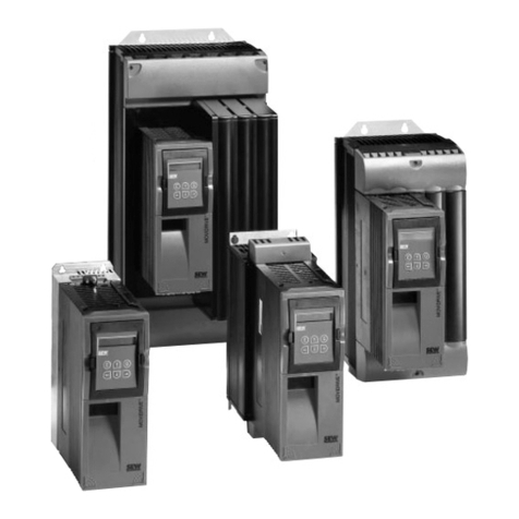
MOVIDYN
®
M D_SCOPE
3
Contents
1 Introduction......................................................................................4
2 Quickstart of a Servo Controller ..............................................................5
3 Installation.......................................................................................6
3.1 Hardware requirements .........................................................................................6
3.2 Installing the program ...........................................................................................6
3.3 Starting the program .............................................................................................6
3.4 Communications requirements..............................................................................7
3.5 Setting up the printer and graphics card................................................................7
4 The Main Program Window ...................................................................8
4.1 Display area...........................................................................................................8
4.1.1 The zoom cursors........................................................................................9
4.1.2 The measured value cursor.........................................................................9
4.1.3 The differential measurement cursors.......................................................10
4.2 Control and display elements...............................................................................11
4.3 M easured value selection.....................................................................................11
4.4 Calculating the effective capacity.........................................................................12
5 The Menu Bar.................................................................................. 13
5.1 “Environment” menu item ...................................................................................13
5.2 “M D_SCOPE” menu.............................................................................................15
5.2.1 “Set Trace...” menu command...................................................................15
5.2.2 “Read in meas. values” menu command...................................................15
5.2.3 “Document...” menu command.................................................................16
5.3 “Parameters” menu item .....................................................................................16
5.3.1 “Controller parameters...” menu command...............................................16
5.3.2 “Test function...” menu command.............................................................17
5.3.3 “Commissioning...” menu command.........................................................17
5.4 “Options” menu item...........................................................................................22
5.4.1 “Select interface...” menu command.........................................................22
5.4.2 “Trace attributes...” menu command.........................................................23
5.4.3 “Language” menu command.....................................................................23
5.4.4 “M D_SHELL-Path” menu command..........................................................24
5.5 “Help” menu item ................................................................................................24
6 Additional Utilies ............................................................................. 25
6.1 D PTER.EXE......................................................................................................25
6.2 HCSELECT.EXE....................................................................................................26
7 Index............................................................................................ 27
