Sharp AR-FN7 User manual

This document has been published to be used for
after sales service only.
The contents are subject to change without notice.
Parts marked with “ “ are important for maintaining the safety of the set.
Be sure to replace these parts with specified ones for maintaining the safety and performance of the set.
SHARP CORPORATION
LASERPRINTEROPTIONS
FINISHER
PUNCHUNIT AR-FN7
MODEL AR-PN1
CODE : 00ZARFN7//A1E
[1] INTRODUCTION. . . . . . . . . . . . . . . . . . . . . . . . . . . . . . . . . . . . 1 - 1
[2] EXTERNAL VIEWS AND INTERNAL STRUCTURES . . . . . . . 2 - 1
[3] UNPACKING AND INSTALLATION . . . . . . . . . . . . . . . . . . . . . . 3 - 1
[4] OPERATIONAL DESCRIPTION . . . . . . . . . . . . . . . . . . . . . . . . 4 - 1
[5] DISASSEMBLY AND ASSEMBLY. . . . . . . . . . . . . . . . . . . . . . . 5 - 1
[6] MAINTENANCE . . . . . . . . . . . . . . . . . . . . . . . . . . . . . . . . . . . . 6 - 1
[7] MACHINE OPERATION . . . . . . . . . . . . . . . . . . . . . . . . . . . . . . 7 - 1
[8] ADJUSTMENTS . . . . . . . . . . . . . . . . . . . . . . . . . . . . . . . . . . . . 8 - 1
[9] TROUBLESHOOTING . . . . . . . . . . . . . . . . . . . . . . . . . . . . . . . 9 - 1
[10] SIMULATIONS. . . . . . . . . . . . . . . . . . . . . . . . . . . . . . . . . . . . . 10 - 1
[11] ELECTRICAL SECTION. . . . . . . . . . . . . . . . . . . . . . . . . . . . . 11 - 1
AR-FN7
CONTENTS
!

CONTENTS
[1] INTRODUCTION
1. Product outline . . . . . . . . . . . . . . . . . . . . . . . . . . . . . . . 1-1
2. Configuration . . . . . . . . . . . . . . . . . . . . . . . . . . . . . . . . 1-1
3. Specifications. . . . . . . . . . . . . . . . . . . . . . . . . . . . . . . . 1-2
[2] EXTERNAL VIEWS AND INTERNAL STRUCTURES
1. External view . . . . . . . . . . . . . . . . . . . . . . . . . . . . . . . . 2-1
2. Internal structure . . . . . . . . . . . . . . . . . . . . . . . . . . . . . 2-1
3. Finisher and saddle section . . . . . . . . . . . . . . . . . . . . . 2-2
4. Puncher section (AR-PN1). . . . . . . . . . . . . . . . . . . . . . 2-3
[3] UNPACKING AND INSTALLATION
1. AR-FN7 . . . . . . . . . . . . . . . . . . . . . . . . . . . . . . . . . . . . 3-1
2. AR-PN1 . . . . . . . . . . . . . . . . . . . . . . . . . . . . . . . . . . . . 3-4
[4] OPERATIONAL DESCRIPTION
1. Basic Operations . . . . . . . . . . . . . . . . . . . . . . . . . . . . . 4-1
2. Feed/Drive System. . . . . . . . . . . . . . . . . . . . . . . . . . . . 4-4
3. Stapling Operation . . . . . . . . . . . . . . . . . . . . . . . . . . . . 4-7
4. Delivery Tray Operation . . . . . . . . . . . . . . . . . . . . . . . . 4-10
5. Saddle Unit. . . . . . . . . . . . . . . . . . . . . . . . . . . . . . . . . . 4-11
6. Puncher Unit (option) . . . . . . . . . . . . . . . . . . . . . . . . . . 4-14
7. Detecting Jams. . . . . . . . . . . . . . . . . . . . . . . . . . . . . . . 4-16
8. Power Supply System. . . . . . . . . . . . . . . . . . . . . . . . . . 4-18
[5] DISASSEMBLY AND ASSEMBLY
1. Finisher Saddle Unit. . . . . . . . . . . . . . . . . . . . . . . . . . . 5-1
2. Puncher Unit(option). . . . . . . . ........... . . . . . . . 5-13
[6] MAINTENANCE
1. Maintenance System Table. . . . . . . . . . . . . . . . . . . . . . 6-1
2. Punch dust process (with the punch unit installed). . . . 6-1
[7] MACHINE OPERATION
1. Staple sort mode. . . . . . . . . . . . . . . . . . . . . . . . . . . . . . 7-1
2. Setup by the printer driver. . . . . . . . . . . . . . . . . . . . . . . 7-2
3. Using the finisher functions in the copy mode. . . . . . . . 7-2
[8] ADJUSTMENTS
1. Finisher/saddle unit. . . . . . . . . . . . . . . . . . . . . . . . . . . . 8-1
2. Puncher unit (option). . . . . . . . . . . . . . . . . . . . . . . . . . . 8-1
[9] TROUBLESHOOTING
1. Outline. . . . . . . . . . . . . . . . . . . . . . . . . . . . . . . . . . . . . . 9-1
2. Trouble code . . . . . . . . . . . . . . . . . . . . . . . . . . . . . . . . . 9-1
3. Troubleshooting. . . . . . . . . . . . . . . . . . . . . . . . . . . . . . . 9-2
[10] SIMULATIONS
1. Finisher/Saddle unit . . . . . . . . . . . . . . . . . . . . . . . . . . . 10-1
2. Puncher unit (option). . . . . . . . . . . . . . . . . . . . . . . . . . . 10-1
[11] ELECTRICAL SECTION
1. LEDs and Check Pins by PCB . . . . . . . . . . . . . . . . . . . 11-1
2. Wiring diagram (AR-FN7) . . . . . . . . . . . . . . . . . . . . . . . 11-2
3. Wiring diagram (AR-PN1) . . . . . . . . . . . . . . . . . . . . . . . 11-4
!

AR-FN7/PN1 INTRODUCTION 1-1
[1] INTRODUCTION
1. Product outline
This unit is installed to the following machines to perform the after-process of output paper from a printer, a copier, or a fax machine.
1) Employment of the through-type stapler
Employment of the through-type stapler allows to make saddle stitch by one stapler.
2) 3 kinds of auto staple functions
There are 3 staple positions available. (One position in the front, one position at the back, 2 positions at the center)
3) Saddle stitch function
Up to10 sheetsof paper can be stapled at the centerand folded in half and discharged.
4) Punch function (Option)
By installation of a puncher unit, paper can be punched to make holes for a binder. (Applicable for 64 - 128g/m². OHP films cannot be used.)
2. Configuration
1. Before installation of this unit, the large-capacity desk (AR-D13) or the 3-stage desk (AR-D14) must be installed in advance.
(When installing the AR-D13/D14, the option power unit (AR-DC1) is required.)
2. When installing this unit, the duplex module (AR-DU3) must be installed together.
3. This unit cannot be installed with the following units:
•Duplex module (AR-DU4) with the manual paper feed tray
•Paper exit tray (AR-TE4)
•Multi-purpose tray (AR-MU1)
•Finisher (AR-FN6)
Applicable models AR-P350 / P450, AR-M350 / M450
Output units
AR-FN7
AR-PN1
Scanner rack
Saddle stitch finisher
Punch unit
Multi purpose drawer
Stand/3 x 500 sheet paper drawer
Stand/MPD & 2000 sheet
Duplex module/bypass tray
Duplex module
B/W scanner module/DSPF
Saddle stitch finisher
Finisher
Mail-bin stacker
Exit tray
Punch unit
PS3 expansion kit
Facsimile expansion kit
Print server card
Hard disk drive
Power supply unit
Upper exit tray extension
Multi-function controller board
Fax memory (8 MB)
Network scanner expansion kit
*1
*1
=Any of the units must be installed together.
*1
= Must be installed together. = Cannot be installed together.
Simultaneous
installation
not allowed
Simultaneous installation not allowed
Simultaneous installation is required
Simultaneous
installation is required
B/W scanner module/DSPF(AR-EF1)
Upper exit tray
extension
(AR-TE4)
Finisher
(AR-FN6)
Mail-bin stacker
(AR-MS1)
Stand/MPD & 2000 sheet
paper drawer
(AR-D13)
Power supply unit
(AR-DC1)
Multi purpose drawer
(AR-MU1)
Stand/3 x 500 sheet
paper drawer
(AR-D14)
Saddle stitch
finisher
(AR-FN7)
Duplex
module/bypass
tray(AR-DU4)
Exit tray
(AR-TE3 or AR-DU4 Standard)
Duplex module
(AR-DU3)
!"#

AR-FN7/PN1 INTRODUCTION 1-2
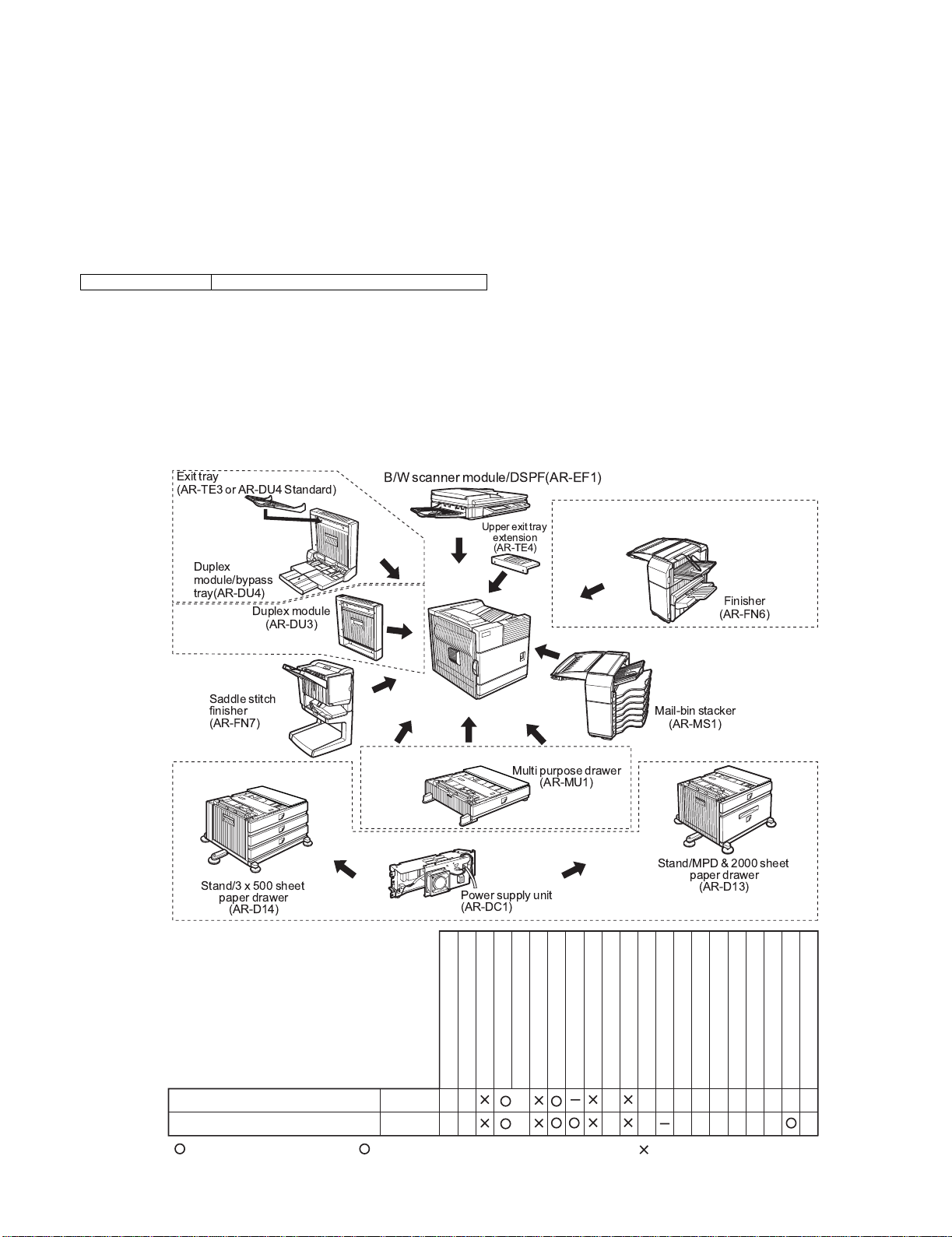
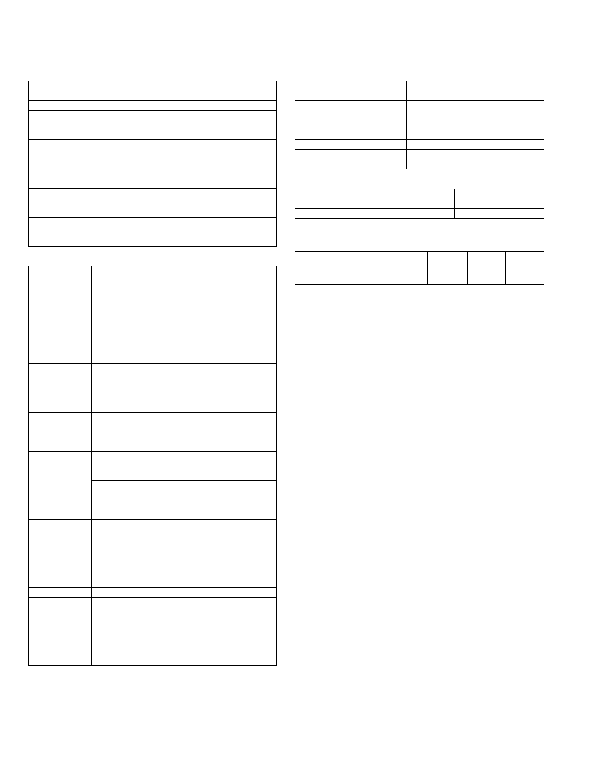
3. Specifications
A. AR-FN7
(1) Basic specifications
(2) Finishing section
(3) Saddle stitch section
B. AR-PN1
4. Consumable parts
Type Console type finisher
Transport speed 35/45 ppm
Transport reference Center reference
Tray type
(Number of trays) Upper tray Lift-up/down offset tray
Lower tray Book tray for saddle stitch
Paper exit direction Face down
Paper exit paper size A3, B4, A4, A4R, B5, B5R, A5R,
11" x 17", 8.5" x 14", 8.5" x 13",
8.5" x 11", 8.5" x 11"R,
5.5" x 8.5"R
Executive
Power consumption 50W or below
Power source Supplied from the option power
(DC24V, 2.7A)
External dimensions (W x D x H) 621 x 603 x 1000 (mm)
Occupying dimensions (W x D) 718 x 603 (mm)
Weight About 39kg
Capacity of
paper exit and
load
Non-staple 1,000 sheets (Small size)
500 sheets (Large size)
Staple sort 30 sheets
Max 1,000 sheets (Small size)
500 sheets: (Large size)
Large size A3, B4,
11" x 17", 8.5" x 14", 8.5" x 13"
Small size A4R, B5, B5R, A5R,
8.5" x 11", 8.5" x 11"R, 5.5" x 8.5"R
Executive
Offset function Provided
(Output paper size except for A5R, 5.5" x 8.5"R)
Paper size which
can be stapled A3, B4, A4, A4R, B5,
11" x 17", 8.5" x 14", 8.5" x 13", 8.5" x 11",
8.5" x 11"R
Kinds and
weights of paper
to be discharged
Normal paper 60 - 12g/m² (16 - 34lbs)
Index paper 176g/m² (47lbs)
Cover paper 200 - 205g/m² (54 - 55lbs)
OHP
Quantityofpaper
to be stapled
(Max.)
50 sheets
(Small size, 128g/m² x 2 + 80g/m² x 48)
25 sheets (Large size, 80g/m² x 25)
Large size A3, B4,
11" x 17", 8.5" x 14", 8.5" x 13"
Small size A4, A4R,
8.5" x 11", 8.5" x 11"R, B5
Stapling 3 kinds
(One in the front, one at the back: two positions)
two positions A3, B4, 11" x 17", 8.5" x 14",
8.5" x 13", A4, 8.5" x 11", B5
one at the back A3, B4, A4, A4R, B5
one in the front 11" x 17", 8.5" x 14", 8.5" x 13",
8.5" x 11", 8.5" x 11"R, Executive
Staple supply Staple cartridge replacement
Staple detection Staple empty
detection Provided
Cartridge
empty
detection
Provided
Staple jam
detection Provided
Stapling type Center stapling: Center folding
Stapling position 1200mm pitch from the paper center
Size of paper applicable for
saddle stitchA3, A4R, B4,
11" x 17", 8.5" x 11"R
Paper weight 64 - 80g/m²
(Cover: 64 - 128g/m²)
Book tray stacking type Fixed
Quantity of paper to be stapled 10 sets (6 - 10 pages)
20 sets (1 - 5 pages)
Type Punch unit
No. ofpunch holes2/3 holes
Size of paper applicable for punching Max. A3, Min. B5R
Name Content Life Product
name Remark
Staple cartridge Staple cartridge x 3 5000 x 3 AR-SC2
$ !"#

AR-FN7/PN1 EXTERNAL VIEWS AND INTERNAL STRUCTURES 2-1
[2] EXTERNAL VIEWS AND INTERNAL STRUCTURES
1. External view
2. Internal structure
A. Finisher section
Fig. F01-301-01
B. Saddle section
Fig. F01-301-02
C. Puncher section (Option)
Fig. F01-301-03
[1] Stapler compiler
[2] Top cover
[3] Stapler section
[4] Front cover
[5] Saddle stitch tray
[6] Offset tray
[1] Paper exit tray
[2] Alignment plate (Front, back)
[3] Paddle
[4] Paper exit roller
[5] Process tray stopper
[6] Transport roller
[7] Puncher section (Option)
[8] Paper exit belt
[9] Bundle exit roller
[10] Stapler
[11] Saddle section
[1]
[2]
[3]
[5]
[6]
[4]
[1] [2]
[8]
[3] [7][5][4] [6]
[9] [10] [11]
[1] Book making stopper
[2] Book making tray
[3] Bundle transport roller
[4] Book making exit roller
[5] Paper folding roller
[6] Paper pushing plate
[1] Dice
[2] Cam
[3] Punch
[4] Punch dust box
[5]
[3] [4][2] [6]
[1]
[3][1] [2] [4]
!" #$%&

AR-FN7/PN1 EXTERNAL VIEWS AND INTERNAL STRUCTURES 2-2
3. Finisher and saddle section
A. Sensor
Fig. F05-201-01
B. Motor and PWB
Fig. F05-201-02
Code Name Active condition Remark
ES Entry sensor Paper detected : "H"
PHPS Paddle home position
sensor Paddle HP : "H"
ARHPS Bundle roller home
position sensor Oscillation guide
HP : "H"
FJHPS Alignment home position
sensor (front) Alignment tray (F)
HP : "H"
RJHPS Alignment home position
sensor (rear) Alignment tray (R)
HP : "H"
AS Alignment tray sensor Paper detected : "H"
OBHPS Exit belt home position
sensor Paper exit belt HP : "H"
BES Tray paper sensor Tray paper detected :
"H"
SLS Paper level sensor Paper detected : "H"
FPS Bookbinding position
sensor Paper detected : "L"
FHPS Bookbinding home
position sensor Folding operation
HP : "L"
FRHPS Bookbinding roller HP
sensor Bundle transport roller
HP : "H"
FES Bookbinding paper
sensor Paper detected : "H"
FE Bookbinding clock
sensor
ULS Lift upper sensor Tray upper limit detected
: "H"
LLSLift lower sensorTraylower limitdetected
: "H"
ES
PHPS
ARHPS
ULS
RJHPS
FPS FHPS
ES CL1
OBHPS
SLS
BES AS
JS
SSS
FDSW
FES
FE
LE
LLS
FJHPS
FDS
TCS
STHPS
SPS
FRHPS
SHPS
LE Lift lock sensor
SHPS Slide home position
sensor Stapler HP : "H"
STHPS Stapler home position
sensor Stapler stapling HP : "L"
SPS Self prime sensor Cartridge staple
detected : "L"
SS Staple sensor Stapler cartridge
detected : "L"
FDS Front door sensor Front cover open : "H"
TCS Upper cover sensor Upper cover open : "H"
FDSW Front door switch Front door closed : "H"
JS Joint switch Printer connected : "H"
SSS Stapler safety switch Oscillationguideclosed:
"H"
Code Name Active condition Remark
FFM Transport motor Paper transport
FPM Paddle motor Oscillation guide drive,
paper exit to offset tray
FAM Bundle exit motor Paper exit operation
FFJM Alignment motor
(front) Alignment plate (F) drive
FRJM Alignment motor (rear) Alignment plate (R) drive
FLM Shift motor Paper exit tray up/down
FFSM Stapler/Fold motor Stapling/paper folding
FSM Slide motor Staple unit sliding
Code Name Active condition Remark
FFSM
FSM
FRJM
FFJM
FAM
FLM
FFM
FPM
Finisher Control PWB
!" #$%&

AR-FN7/PN1 EXTERNAL VIEWS AND INTERNAL STRUCTURES 2-3
4. Puncher section (AR-PN1)
A. Sensor
Fig. F05-202-01
B. Motor
Fig. F05-202-02
C. PWB
Fig. F05-202-03
Code Name Active condition Remark
Punch home position
sensor Punch HP
detected:"L" In the punch unit
PSHPS Punch side home
position Punch slide unit HP
detected:"H" In the punch unit
PEPunch dustsensorIn the punch unit
CodeNameActive conditionRemark
FPNMPunch motorPunchdrive
FPSM Punch side motor Punch slide unit transverse move
PSHPS
PHPS
PE
FPSM
FPNM
Code Name
[1] Punch driver PWB
[2] Side resist photo sensor PWB
[3] Side resist LED PWB
[4] Dust full photo sensor PWB
[5] Dust full LED PWB
[1]
[2]
[3]
[5]
[4]
' !" #$%&

AR-FN7/PN1 UNPACKING AND INSTALLATION 3-1
[3] UNPACKING AND INSTALLATION
1. AR-FN7
<Before installation>
For installation of AR-FN7, an optional stand/paper drawer (stand/MPD &
2000 sheet drawer or stand/3 x 500 sheet paper drawer) and a duplex
module (AR-DU3) must have been installed. Also a power supply unit
(AR-DC1) is needed.
1) Turn off the main switch of the main unit of the printer.
<1> Turn the main switch located on the front side of the main unit to the
"OFF" position.
<2> Then remove the power plug of the main unit from the outlet.
2) Attach the lock securing plate to the duplex module.
<1> Remove the screw from the right side of the duplex module.
<2> Attach the lock securing plate to the duplex module using the
screws C and D (one for each).
3) Work the stand/paper drawer.
<1> Open the pawl of the left adjuster to both sides to unlock it that is
located at the lower left of the stand/paper drawer and remove the
left adjuster.
<2> Cut out the two mounting holes of the stand/paper drawer using a
screwdriver or the like and remove burrs using a flat-blade
screwdriver or the like.
4) Attach the grounding plate to the stand/paper drawer.
<1> Remove the two screws that fix the exterior of the stand/paper
drawer.
<2> Then, attach the front mounting plate and the rear mounting plate to
the stand/paper drawer using screws C (two for each).
<Parts included>
Staple unit: 1 pc.
Connecting plate:
1 pc.
Front grounding
plate: 1 pc. Rear grounding
plate: 1 pc.
Front cover:
1 pc.
Plate R: 1 pc.
Lock securing plate:
1 pc.
Screws A
(M4x6):
6 pcs.
Screws B
(M4x10):
2 pcs.
Screws C
(M4x18):
7 pcs.
Screws D
(M4x10 with rosette):
1 pcs.
Stapling position labels:
2 sheets
"OFF"
Screw D
Screw C
Lock securing plate
Screw
<1>
<2> <2>
Mounting
holes
Mounting
holes
Left adjuster
Pawl
Screws C
Screws C
Exterior
fixing screw
Exterior
fixing screw
Front grounding plate
Rear grounding plate
! #$! %& '()

AR-FN7/PN1 UNPACKING AND INSTALLATION 3-2
5) Install the staple unit to the finisher.
<1> Remove the two pieces of packing tape from the locations shown in
the illustration.
<2> Open the front cover of the finisher and insert the staple unit.
6) Attach the cover to the finisher.
<1> Attach the plate R to the position shown in the illustration and
secure it using two screws A.
<2> Attach the front cover to the finisher, and secure the upper part
using two screws B and the lower part using two screws A.
7) Connect the finisher to the stand/paper drawer.
<1> Remove the cover from the finisher stand.
<2> Attach the connecting plate to the finisher using two screws A.
<3> Reattach the cover to its original position.
<4> Cut out the two mounting holes for the connecting plate at the lower
part of the stand/paper drawer in a similar way to step 3).
<5> Attach the finisher connecting plate to the stand/paper drawer using
two screws C.
8) Check and adjust the height of the finisher.
Move the finisher toward the printer and check to see if the guide pin
of the locking plate is inserted smoothly to the connecting hole of the
finisher.
Packing tape
Packing tape
Front cover
Screws A
Screws A
Screws B
Plate R
Cover
Screws A
Connecting plate
Finisher stand
Screws C Connecting plate
Stand/paper drawer
Guide pin
Connecting
hole
* ! #$! %& '()

AR-FN7/PN1 UNPACKING AND INSTALLATION 3-3
If it is not inserted smoothly, use the following procedure to adjust the height.
a. If the guide pin of the lock securing plate is not aligned with the
connecting hole of the finisher:
<1> Loosen the screw at the rear adjusting portion.
<2> Remove the cap using a flat-blade screwdriver or the like and adjust
the height adjusting pin so that the guide pin is positioned to the
center of the connecting hole of the finisher.
<3> Loosen the screw at the front adjusting portion.
<4> Adjust the height adjusting pin so that the exterior lines are aligned
as shown in the illustration.
<5> If the guide pin can be inserted smoothly, tighten the screws at the
front and rear adjusting portions and mount the caps.
b. If the guide pin of the locking plate matches to the connecting
hole of the finisher:
<1> Push the finisher into the main unit.
<2> If the gap between the main unit of the printer and the finisher is not
uniform at the top and the bottom, remove the caps from the front
side and the rear side of the finisher stand using a flat-blade
screwdriver or the like and remove the screw of the sub covers on
the front side and the rear side to remove the sub covers.
<3> Then, loosen the four screws at the adjusting portions indicated in
the illustration and turn the height adjusting screws on the front side
and the rear side so that the gap becomes uniform.
<4> If the gap becomes uniform, tighten the screws at the adjusting
portions and reattach the caps and sub covers.
9) Paste the stapling position labels.
<1> Paste the labels to the positions shown in the illustration.
10) Remove the AC inlet cover from the rear cabinet of the stand/paper
drawer.
<1> Remove the screw that fixes the AC inlet cover and then remove the
AC inlet cover.
11) Connect the finisher connector.
<1> Connect the finisher connector to the stand/paper drawer.
<2> Tighten the screw of the connector.
12) Turn on the main switch of the main unit.
<1> Insert the power plug of the main unit to the outlet.
<2> Turn on the main switch of the main unit.
Height
adjusting
screw
Height adjusting
screw
Screw at
adjusting
portion
Screw at adjusting portion
Cap
Cap
Front side
Rear side
Front cover
Exterior lines
Exterior lines
Finisher stand
Gap
Gap
Sub cover
Sub cover
Screw
Screw
Screw at adjusting portion
Height
adjusting screw
Screw at adjusting portion
Cap
Cap
Front side
Rear side
ScrewAC inlet cover
Screw
Connector
"ON"
! #$! %& '()

AR-FN7/PN1 UNPACKING AND INSTALLATION 3-4
2. AR-PN1
<Before installation>
For installation of AR-PN1A/PN1B/PN1C/PN1D, a saddle stitch finisher
(AR-FN7) must have been installed.
1) Turn off the main switch of the main unit of the printer.
<1> Turn the main switch located on the front side of the main unit to the
"OFF" position.
<2> Then remove the power plug of the main unit from the outlet.
<3> Loosen the screw and remove the connector of the finisher.
2) Remove the front cover from the right front of the finisher.
<1> Remove the screws A and B (two for each) that secure the finisher
front cover and remove the front cover.
3) Remove the front cabinet and the rear cabinet from the finisher.
<1> Open the front door of the finisher and remove the jam handling dial.
<2> Remove the two front cabinet securing screws, pull out the staple
unit until it stops, then remove the pawl of the front cabinet in the
direction indicated by the arrow and remove the front cabinet.
<3> Remove the three screws that fix the rear cabinet and remove the
rear cabinet.
At this time, remove the relay harness through the opening of the
rear cabinet.
<3> Remove the three rear cabinet securing screws, remove the pawl in
the direction indicated by the arrow, and remove the rear cabinet.
At this time, remove the relay harness through the opening of the
rear cabinet.
Parts included
Screw
(M4 x 6 with rosette)
: 1 pc.
Harness A (purple): 1 pc. Harness B (orange): 1 pc.
Dust box label:
1 sheet Hole punch position label:
2 sheets
"OFF"
Screws
Connector
Screws B
Screws A
Front cover
Jam handling dial
Staple unit
ScrewsFront cabinet
Pawl
Screw
Relay harness
Opening for
relay harness
Screw
Rear
cabinet
Pawl
+ ! #$! %& '()

AR-FN7/PN1 UNPACKING AND INSTALLATION 3-5
4) Remove the top cover.
<1> Remove the four top cover securing screws and remove the top
cover.
<2> Remove the four pawls from the top cover and separate the cover
into the upper and lower portions. Reuse the upper portion.
5) Attach the punch module.
<1> Insert the two bosses of the punch unit into the boss holes of the
finisher and fix the punch module using three screws.
Note:For the screws, use a supplied screw and the two screws that have
been removed in step 4).
6) Connect the harness of the punch module to the PWB of the finisher.
<1> Remove the clamps that fix the harness, handle the wiring of
harness A (purple) and harness B (orange), and fix them with the
clamps.
7) Reattach the covers that have been removed.
<1> Hang the two pawls of the top cover and secure them using the two
screws.
<2> Pass the relay harness to the rear cabinet and secure the rear
cabinet using the three screws.
Top cover
Screw
Top cover
Pawl
Pawl
Boss
Boss hole Boss
Boss hole
Screw (with rosette) (supplied with this module)
Screw
Screw
Punch module
Clamps
Clamps
Harness A (purple)
Harness B (orange)
Harness A (purple)
Harness B (orange)
Screw Screw
Top cover
Pawl
Screw
Relay harness
Opening for
relay harness
Screws
Rear cabinet
, ! #$! %& '()

AR-FN7/PN1 UNPACKING AND INSTALLATION 3-6
<3> Remove the lock release lever that has been attached to the front
cabinet.
Reattach the front cabinet to its original position, push in the staple
unit, and attach it using the two screws.
Insert the protrusion (B) of the lock release lever that has been
removed before to the hole (C) of the latch arm.
After attaching it, move the lever to check that it moves smoothly.
If the lever does not move smoothly, remove the lock release lever
by releasing the pawl at the lower part of the lock release lever using
a flat-blade screwdriver or the like and then insert it again.
<4> Reattach the jam handling dial and close the front cover.
8) Reattach the front cover to the right front of the finisher.
<1> Attach the front cover using the screws A and B (two for each).
9) Paste the dust box label to the top cover.
<1> Paste the supplied dust box label to the location indicated in the
illustration.
10) Connect the connector to the stand/paper drawer and connect the
AC cord of the power supply unit to the main unit of the printer.
<1> Connect the connector of the relay harness of the finisher to the
stand/paper drawer and tighten the screws of the connector.
11) Paste the label.
(Paste it only if the scanner module is installed.)
<1> Paste the label to the position shown in the illustration.
Staple unit
Screws Front cabinet
Lock release lever (A)
Projection (B)
Latch arm Pawl (D)
(C)
Jam handling dial
Screws B
Screws A
Front cover
Screws
Connector
AC cord
- ! #$! %& '()

AR-FN7/PN1 OPERATIONAL DESCRIPTION 4-1
[4] OPERATIONAL DESCRIPTION
1. Basic Operations
A. Specifications
The finisher serves to deliver sheets coming from its host machine. The
mode of delivery may be non-sort stack, job offset*, or staple delivery.
The saddle unit built into the finisher is used to fold a stack of sheets
coming from the finisher unit in half for delivery.
All these operations are controlled by various commands sent by the
host machine in addition to the commands from the finisher controller
PCB.
The puncher unit (option) is designed for installation to the pickup
assembly of the finisher, and is used to punch holes in sheets coming
from the host machine.
The above operations are controlled with various commands from the
finisher controller PCB as well as the commands from the punch
controller PCB.
Fig.F02-101-01
NOTE:The position of delivery is shifted to the front/rear for each stack to
assist sorting.
B. Outline of the Electrical Circuitry
The sequence of finisher operations is controlled by the finisher
controller PCB. The finisher controller PCB is a 16-bit microprocessor
(CPU),and isalso used for communication with the host machine (serial).
The finisher controller PCB drive motors and other loads in response to
the various commands from the host machine. It also communicates
such data as on the states of various sensors and switches to the host
machine by way of the serial communication line.
The ICs mounted to the finisher controller PCB have the following
functions:
•IC13 (CPU)
Controls sequence of operations.
•IC12 (EEP-ROM)
Backs up adjustment settings.
•IC6 (EP-ROM)
Stores sequence programs.
•IC11 (communication IC)
Communicates with the host machine.
•IC1 (regulator IC)
Generates 5 V.
F02-102-01 shows the flow of signals between finisher and options
controller:
Fig.F02-102-01
Puncher unit drive
system (puncher unit;
option)
Alignment drive system
Stapler drive system
Delivery drive system
Feed drive system
Tray drive system
Saddle unit
drive system
Control system
Host machine DC
controller PCB
CPU
Punch controller
PCB
Finisher
controller
PCB
IC13
CPU
IC12
EEP-ROM
IC11
Communica-
tion IC
IC6
EP-ROM
IC1
Regulator IC
Motor
Clutch
Switch
Sensor
Motor
Sensor
Finisher unit
Puncher unit (option)
"# $%&'(

AR-FN7/PN1 OPERATIONAL DESCRIPTION 4-2
C. Inputs to and Outputs from the Finisher Controller PCB
•Inputs to the Finisher Controller PCB (1/2)
Fig.F02-103-01
•Inputs to the Finisher Controller PCB (2/2)
Fig.F02-103-02
•Outputs from the Finisher Controller PCB (1/2)
Fig.F02-103-03
•Outputs from the Finisher Controller PCB (2/2)
Fig.F02-103-04
Inlet sensor
Paddle home
position sensor
Swing guide
home position
sensor
Aligning plate
home position
sensor (front)
Aligning plate
home position
sensor (rear)
Delivery belt
home position
sensor
Processing
tray sensor
OBHPS
AS
RJHPS
FJHPS
ARHPS
PHPS
ES CN44-3
-2
-1 CN16-10
Finisher controller PCB
When the sensor
detects paper, ‘1’ .
+5 V
ENT_S
+5 V
PDL_HP
+5 V
F JOG_HP
When the aligning
plate (rear) is at
home position, ‘1’.
+5 V
R JOG_HP
+5 V
ADJ_TRAY_S
When the delivery belt
is at home position, ‘1’.
+5 V
EJCT_BLT_HP
+5 V
BDL_ROL_HP
-11
-12
-2
CN43-1
-3 -2
CN42-3
-1
CN9-1
-2
-3
CN51-1
-2
-3 When the paddle is at
home position, ‘1’.
CN55-3
-2
-1 CN9-7
-8
-9
-2
CN54-1
-3 -2
CN53-3
-1 When the swing guide
is at home position, ‘1’.
Tray paper sensor
Paper surface
sensor
Folding position
sensor
FPS
SLS
BES When paper is present
on the tray,‘1’.
+5 V
TRY_EMPS
When the paper
surface is detected,
‘1’.
+5 V
LVL_S
+5 V
BIND_P
CN4
-2
-3
CN23-3
-2
-1 When the aligning
plate (front) is at
home position, ‘1’.
CN5-13
-14
-15
CN36-3
-2
-1
CN30-3
-2
-1 CN5-1
-2
-3
-2
CN29-1
-3 -8
CN28-9
-7 When the sensor
detects paper, ‘1’.
CN31-3
-2
-1 -4
-5
-6
CN32-3
-2
-1 -7
-8
-9
-4
-5
-6
-7
-8
-9
-6
-5
-4
-3
-2
-1
CN35-3
-2
-1 CN5-10
-11
-12
-2
CN34-1
-3 -2
CN33-3
-1
CN39-3
-1
-2 CN16-1
-3
-2
-3
CN38-1
-2 -7
CN37-9
-8
BIND_L When paper is
detected, ‘0’.
When LED is lit, ‘1’.
Folding home
position sensor
Stack feed roller
(upper) home
position sensor
Bind tray sensor
Staple/fold motor
clock sensor
Shift upper limit
sensor
Shift motor clock
sensor
Shift lower limit
sensor
LE
LLLS
ULS
FE
FES
FRHPS
FHPS CN40-3
-2
-1 CN16-4
Finisher controller PCB
When at folding home position,‘0’.
+5 V
BIND_HP
+5 V
BIND_ROL_HP
+5 V
BIND_CLK
When the tray is at the
upper limit, ‘1’.
+5 V
SIFT_UPLMT
+5 V
SIFT_DNLMT
While the shift motor
is rotating, alternates
between ‘1’ and ‘0’.
+5 V
SIFT_CLK
+5 V
BIND_EMPS
-5
-6
-5
CN38-4
-6 -5
CN37-6
-4
-7
-8
-9
CN41-3
-2
-1 When the stack feed roller
(upper) is at home position, ‘1’.
CN47-3
-2
-1 CN15-1
-2
-3 When the sensor
detects paper, ‘1’.
Front door sensor
Upper cover sensor
TCS
FDS
When the front door
is open, ‘1’.
+5 V
FDOOR_S
When the upper cover
is open, ‘1’.
When the paper is
full, ‘1’.
+5 V
TOPCOV_S
CN9-6
-4
-5
CN52-1
-3
-2 When the staple/fold motor is
rotating, alternates between
‘1’ and ‘0’.
CN15-10
-11
-12
CN50-3
-2
-1
CN49-3
-2
-1 CN15-7
-8
-9 When the tray is at the
lower limit, ‘1’.
CN48-3
-2
-1 -5
-6
CN25-3
-2
-1 -8
-9
CN24-3
-2
-1 CN4-4
-5
-6
Full stack sensor
XXXX +5 V
PAPER_F
CN73-3
-2
-1 CN19-1
-2
-3
-7
-8
-9 -3
-2
-1
CN15-4
CN4-7
FDSW
Joint switch N. O. +24 VP
When the front
door is closed, ‘1’.
JS
SSS
Front door switch
Stapler safety
switch
N. O.
N. O.
JOINT SW
FRONT SW
STPLSAFE SW
CN69-2
-1
CN8-6
-5
CN8-4
-3
CN8-2
-1
CN68-2
-1
CN66-2
-1 When the swing
guide is closed, ‘1’.
When connected to
the host machine,‘1’.
Finisher controller PCB
When the drive is transmitted,
‘1’.
Feed motor
FEEDMTR_A
+24 V
CN10-1
-1
CN62-5
Paddle motor +24 V
FPM
FFC B_CLU
+24 V
CN72
-1
-2 -2
-1 CN18-1
-2
Binding clutch
Delivery motor +24 V
FAM
Alignment motor
(front)
+24 V
FFJM
Alignment motor
(rear) +24 V
FRJM
Switches between‘1’ and
‘0’according to the
direction of motor rotation.
-2
-3
-4
-5
-6
FFM
-2
-3
-4
-5
-6
CN56
-6
-5
-4
-3
-2
-1
FEEDMTR_*A
FEEDMTR_B
FEEDMTR_*B
PDLMTR_A Switches between‘1’ and
‘0’according to the
direction of motor rotation.
PDLMTR_*A
PDLMTR_B
PDLMTR_*B
CN10-7
-8
-9
-10
-11
-12
-1
-2
-3
-4
-5
-6
CN57
-6
-5
-4
-3
-2
-1
EJCTMTR_A Switches between‘1’ and
‘0’according to the
direction of motor rotation.
EJCTMTR_*A
EJCTMTR_B
EJCTMTR_*B
CN13-1
-1 -2
-3
-4
-5
-6
-2
-3
-4
-5
-6
CN59
-6
-5
-4
-3
-2
-1
CN3-1
-2
-3
-4
-5
FJOGMTR_A Switches between‘1’ and
‘0’according to the
direction of motor rotation.
FJOGMTR_*A
FJOGMTR_B
FJOGMTR_*B
CN63-1
-2
-3
-4
-5
-4
-3
-2
-1
CN64-5 CN3-6
-7
-8
-9
-10
CN65-1
-2
-3
-4
-5
-4
-3
-2
-1
RJOGMTR_A Switches between‘1’ and
‘0’according to the
direction of motor rotation.
RJOGMTR_*A
RJOGMTR_B
RJOGMTR_*B
Finisher controller PCB
Shift motor
SIFTMTR_1 Switches between‘+’ and
‘–’according to the
direction of motor rotation.
CN6-1
-2
FLM
-2
-1
CN70
-2
-1 SIFTMTR_0
-2
-1
-2
-1
-2
-1
CN70
-2
-1
Staple/fold motor
BINDMTR_1 Switches between‘+’ and
‘–’according to the
direction of motor rotation.
CN6-3
-4
FFSM BINDMTR_0
CN71
) "# $%&'(

AR-FN7/PN1 OPERATIONAL DESCRIPTION 4-3
•Inputs to and Outputs from the Finisher Controller
Fig.F02-103-05
D. Inputs to and Outputs from the Punch Controller
PCB(option)
•Inputs to and Outputs from the Punch Controller PCB
Fig.F02-104-01
•Outputs from the Punch Controller PCB
Fig.F02-104-02
Finisher controller PCB
CN72A-5
When the stapler is
connected, ‘0’.
When the cartridge has
staples, ‘0’.
When the staple is at top
the stapler, ‘0’.
When the stapler is at
stapling home position, ‘0’.
When the stapler is at home
position, ‘1’.
Stapler unit
Staple home
position sensor
Staple top
position sensor
Staple empty
sensor
CN11-2
CN11-7
CN11-1
SHPS
+5 V
+5 V
+5 V
STHPS
SPS
SS
+5 V
HOOK_S
STPL_HP
SLID_HP
STPL_CNCT
Host
machine
Communication line
CN2-1
-3
-4
-5
-7
-6
CN1-1
-2
+24 V
+24 V
+5 V
SELF_P
+5 V
Slide home
position sensor
CN11-6
CN11-5
CN11-4
CN11-3
CN72A-4
CN72A-3
CN72A-2
CN72A-6
CN72A-1
CN72A-7
CN72A-5
CN72A-4
CN72A-3
CN72A-2
CN72A-6
CN72A-1
CN72A-7
CN72-5
CN72-4
CN72-3
CN72-2
CN72-6
CN72-1
CN72-7
SLIDMTR_A
SLIDMTR_*A
SLIDMTR_B
SLIDMTR_*B
FSM
CN7-3
CN7-4
CN7-5
CN7-6
CN72B-5
CN72B-4
CN72B-3
CN72B-2
CN72B-5
CN72B-4
CN72B-3
CN72B-2
CN72-10
CN72-11
CN72-12
CN72-13
Switches between‘1’ and
‘0’according to the direction
of motor rotation.
Slide motor
GND
GND
TXD
RXD
Punch controller PCB
XXXX -1
J2008-3 +5 V
PUNCH
-2 -6
J1006-4
-5
SREG1*
SREG2*
SREG3*
-9
-10
-11
J1007-12
-13
SREG4*
-8
PAEND*
-7
Horizontal
registration
home position
sensor
PE
-1
J2009-3 +5 V
CLOCK
-2 -9
J1006-7
-8
Punch home
position sensor
+5 V
+5 V
PT1 PT2 PT3 PT4 PT5
When the hole puncher is
at home position, ‘0’.
PSHPS -1
J2007-3 +5 V
SLIDE
-2 -3
J1006-1
-2
Punch motor
clock sensor While the punch motor
is rotating, alternates
between ‘0’ and ‘1’.
When the punch slide
unit is at home position,
‘1’.
When paper is
detected, ‘0’.
Photosensor PCB
DUSTLED
When the light is
blocked, ‘0’.
Waste full LED PCB
J1005-1
PT131
LED121
DUSTPTR
+5V
4
Waste full photosensor PCB
-2
J1005-3
Punch controller PCB
LED PCB
FPSM
Horizontal
registration
motor
Switches between ‘+’
and ‘–’ according to
the direction of motor
rotation.
When ‘1’, LED goes ON.
Switches the pulse
signals according to
the rotation of the motor.
B*
A*
B
A
J1001-1
-2
-3
-4
FPNM
Punch motor
J1002-1
J1007-6
-1
-5
-4
-3
-2
LED5
LED4LED3LED2 LED1
-2
LEDON5
+5V
LEDON4
LEDON3
LEDON2
LEDON1
* "# $%&'(

AR-FN7/PN1 OPERATIONAL DESCRIPTION 4-4
2. Feed/Drive System
A. Outline
The machine performs the following in response to the commands
coming from its host machine on the sheets arriving from the host
machine for delivery: simple stacking, job offset, and stapling or folding
(in two).
Ifa punch unit(option) is installed, the sheets are punchedanddelivered
to the delivery tray.
Sheets may be delivered in either of five ways (including one for the
puncher unit):
Fig.F02-201-01
(1)Normal Delivery
a.Simple Stacking
The machine pulls in the sheet once to the processing tray and then
delivers it to the delivery tray.
Fig.F02-201-02
b.Job Offset
The machine pulls the sheet once to the processing tray. It then moves
the sheet to the front or the rear using the aligning plate. When it has
deposited a specific number of sheets, it delivers them in the form of a
stack. When the number ofsheetsstacked onthe processing
tray reaches a specified value, the sheets are delivered in a form of a
stack. Even if the specified value is not reached, stacked sheets are
temporarily delivered when 10 sheets of large-size paper (300 mm or
longer) or 30 sheets of small-size paper (299 mm or shorter) have been
stacked. (5- and STMT-sizes: 10 sheets)
Fig.F02-201-03
c.Stapling
The machine stacks sheets coming from its host machine on the
processing tray. When the number of sheets stacked on the processing
tray reaches a specified value, the finisher staples them delivers the
stapled stack to the delivery tray.
Fig.F02-201-04
PunchingNormal
delivery
Delivery
method
Middle 2-point stapling
Job offset
Simple stacking
Stapling Front 1-point stapling
Rear 1-point stapling
Middle 2-point stapling
StitchingSaddle delivery
Tray
Paper
4th set
(direction of delivery)
Results of offset delivery (4 jobs)
2nd set
3rd set
1st set
"# $%&'(

AR-FN7/PN1 OPERATIONAL DESCRIPTION 4-5
d.Saddle Delivery
The machine deposits a stack of sheets on the processing tray, staples it
(middle 2-point), and then moves it to the saddle unit. The saddle unit
folds the stack in two, and delivers it to the bind tray.
Fig.F02-201-05
B.Feed/Delivery
(1)Outline
The machine forwards the sheets coming from its host machine to the
delivery tray, processing tray, or saddle unit according to the type of
delivery used. The sheets forwarded to the processing tray or the saddle
unit are offset, stapled, or folded.
F02-202-01 shows the motors that are associated with moving and
aligning sheets. These motors are controlled (rotated clockwise or
counterclockwise) by the microprocessor (CPU) on the finisher controller
PCB.
The paper path is equipped with the sensors shown in T02-202-02 used
to monitor the arrival or passage of sheets.
If a sheet fails to arrive at or move past a specific sensor within a specific
period of time, the finisher controller will assume a jam, and stops the
ongoing operation and, at the same time, communicates the presence of
a jam to the host machine.
Table.T02-202-01
Fig.F02-202-01
Notation Name Description Connector on finisher
controller PCB
FFM Feed motor Stepping motor CN10
FPM Paddle motor Stepping motor CN10
FAM Delivery motor Stepping motor CN13
FFJM Alignment plate
motor (front) Stepping motor CN3
FRJM Alignment plate
motor (rear) Stepping motor CN3
FFSM Staple/fold motor Brush DC motor CN6
PI14
FFJM
FFSM
FFC
FSM
FLM
FAM
FRJM FPM FFM
Finisher controller PCB (1/2)
Feed motor
drive signal FEEDMTR
Paddle motor
drive signal PDLMTR
Alignment plate motor
(rear) drive signal RJOGMTR
Bind clutch drive signal B_CLU
Alignment plate motor
(front) drive signal FJOGMTR
Finisher controller PCB (2/2)
Staple/fold motor drive signal BINDMTR
Staple/fold motor clock detect signal
BIND_CLK
Shift motor drive signal SIFTMTR
Delivery motor drive signal EJCTMTR
Slide motor drive signal SLIDMTR
+ "# $%&'(

AR-FN7/PN1 OPERATIONAL DESCRIPTION 4-6
Fig.F02-202-02
Table.T02-202-02
C.Job Offset
(1)Outline
"Job offset" refers to the operation by which the machine delivers a set of
sheets with them pulled forward or backward for sorting.
Switching between the forward and backward directions is made using
an aligning plate (front) and an aligning plate (rear).
The sheet coming between the delivery rollers is fed onto the processing
tray and then fed toward the stopper by the paddle.
A swing guide is at the up position while a sheet is being pulled onto the
processing tray or during alignment. It is at the down position during
stack feeding, stack delivery, or stapling.
At power-on, the finisher controller PCB drives the aligning plate (front)
motor (FFJM) and the aligning plate (rear) motor (FRJM) to return the
two aligning plates to their home positions.
Table.T02-203-01
Fig.F02-203-01
(2)Processing Tray Paper Stacking Operation
A sheet coming between the delivery rollers is fed onto the processing
tray. Then the paddle tapson the sheet surface twice (once for the
second and subsequent sheets) to locate the sheet against the
processing tray stopper.
Fig.F02-203-02
(3)Offset Operation
Each sheet is pulled forward or backward using the aligning plate (front)
and the aligning plate (rear).
The offset operation is performed each time a sheet is pulled onto the
processing tray.
Offsetting in the forward direction
Fig.F02-203-03
Notation Name Description Connector on finisher
controller PCB
ES Inlet sensor Photointerrupter CN16
FPS Fold position sensor Photointerrupter CN16
SensorSymbolConnectorFunctionMotorSymbol
Aligning plate
(front) home
position sensor
FJHPS CN4-3 Drives the
aligning plate
(front)
Aligning
plate
(front)
motor
FFJM
Aligning plate
(rear) home
position sensor
RJHPS CN5-15 Drives the
aligning plate
(rear)
Aligning
plate
(rear)
motor
FRJM
Swing guide
home position
sensor
ARHPS CN9-9 Drives the
swing guide
drive.
Paddle
motor FPM
Paddle home
position sensor PHPS CN9-3 Drives the
paddle
(feeds paper).
Paddle
motor FPM
Finisher controller PCB
FPS
Fold position paper detect signal BIND_P
ES
Inlet paper detect signal ENT_P
Aligning plate
(front)
Alignment plate (front)
motor (FFJM)
Alignment plate (rear)
motor (FRJM)
Light-shielding plate
(Front) Paper
Aligning plate (front) home position sensor (FJHPS)
Light-shielding plate
Aligning plate (rear)
home position sensor (RJHPS)
Aligning plate (rear)
Swing guide
Delivery belt Stack delivery roller (lower)
Processing tray stopper
Paddle Stack delivery roller (upper)
Aligning plate
Paper
Aligning plate (rear)
Sheet to be offset
Tray Aligning plate (front)
, "# $%&'(

AR-FN7/PN1 OPERATIONAL DESCRIPTION 4-7
Offsetting in the backward direction
Fig.F02-203-04
(4)Stack Delivery Operation
Stack delivery takes place when 10 sheets of large-size paper or 30
sheets of small-size paper (A5- and STMT-sizes: 10 sheets) have been
stacked on the processing tray with them offset in either direction.
The paddle motor rotates and the swing guide descends to hold the
paper stack between the upper and lower stack delivery rollers. The
delivery motor rotates in the forward direction to rotate the delivery
rollers, feeding the paper stack in the delivery direction. The delivery belt
home position sensor is turned OFF. The delivery motor is driven a
specified number of pulses, causing the swing guide to ascend. Next,
the paper delivery motor is driven. Next, the delivery motor is driven to
deliver the paper stack with the nails of the delivery belt that rotates in
sync with the stack delivery rollers.
Fig.F02-203-05
Job offset sequence
Fig.F02-203-06
3. Stapling Operation
A.Outline
Staple operation is performed to staple a specified sheets of paper using
a stapler unit.
The stapling position depends on the staple mode and paper size.
When the machine starts immediately after power-on, the finisher
controller PCB drives the slide motor (FSM) to return the stapler unit to
the home position. The stapler unit starts moving toward the front of the
stapler frame. It stops when the slide home position sensor (SHPS) on
the slide PCB located under the stapler unit. Next, the slide motor is
driven a specified number of pulses. The stapler unit moves to rear
standby position at the back of the machine, entering the standby state.
Table.T02-301-01
Fig.F02-301-01
Tray
Aligning plate (rear)
Sheet to be offset
Aligning plate (front)
Swing guide
Host machine delivery signal
Start signal
Inlet sensor (ES)
Processing tray sensor
(AS)
Feed motor (FFM)
Delivery motor (FAM)
Delivery belt home
position sensor (OBHPS)
Paddle motor (FPM)
Paddle home position
sensor (PHPS)
Swing guide home
position sensor (ARHPS)
Stapler safety switch
(SSS)
Alignment motor (front)
(FFJM)
CW rotation CCW rotation
Aligning plate home position
sensor (front) (FJHPS)
Alignment motor (rear)
(FRJM)
Aligning plate home position
sensor (rear) (RJHPS)
360msec
60msec
360msec 360msec 360msec
30msec 220msec
SensorSymbolConnectorFunctionRemarks
Slide home
position sensor SHPS CN11-3 Detects the home
position for the stapler
moving back and forth.
-
Staple home
position sensor STHPS CN11-4 Detects the home
position for the stapling
operation
In the
stapler
Staple empty
sensor SPS CN11-5 Detects presence or
absence of staples in
the cartridge.
In the
stapler
Staple top
position sensor SS CN11-6 Detects the staple top
position. In the
stapler
Function Motor Symbol Remarks
Moves the stapler. Slide motor FSM -
Performs stapling operation. Staple/fold motor FFSM -
Paper stack
Slide motor
(FSM)
Stapler
Slide home position sensor (SHPS)
Light-shielding plate
(Deliver direction)
- "# $%&'(
Other manuals for AR-FN7
1
This manual suits for next models
1
Table of contents
Other Sharp Printer Accessories manuals

Sharp
Sharp AR-DU3 User manual

Sharp
Sharp AR-PB9ML User manual

Sharp
Sharp SF-S55N User manual

Sharp
Sharp ARFX13 - Fax Interface Card User manual

Sharp
Sharp AR-FR4 U User manual

Sharp
Sharp AR-FR22 U User manual

Sharp
Sharp AR-F14N User manual

Sharp
Sharp AR-PB8 User manual

Sharp
Sharp AR-D24 User manual

Sharp
Sharp AR-D15 User manual