AR-RB1 DESCRIPTION OF OPERATION 4 - 2
(1) Initial operation
When the power to the copier is turned on, in order to confirm whether
or not there is paper in the transport path, the paper input motor, upper
turnover motor and lower turnover motor revolve for a predetermined
time.
Even after the predetermined time has passed, if all the transport sen-
sors are OFF and it is determined that there is no paper in the trans-
port path, if within a given period of time at least one transport sensor
turned ON, it is interpreted as paper being present in the transport path
(paper jam).
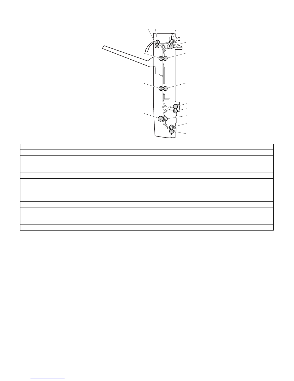
(2) Straight delivery operation
In this operation, the paper discharged from the copier is sent directly
to the paper exit tray or transported to the finisher.
When the paper input motor and upper turnover motor revolve, the
paper input roller and delivery roller rotate in the directions as shown in
the figure below to discharge the paper.
If the paper is delivered to the finisher, it is transported at the same
speed at which it is discharged from the copier.
As the paper is discharged to the paper exit tray, when the trailing
edge reaches a point 50mm from the delivery roller on the copier side,
the speed of the delivery roller increases, and the paper is discharged
to the tray.
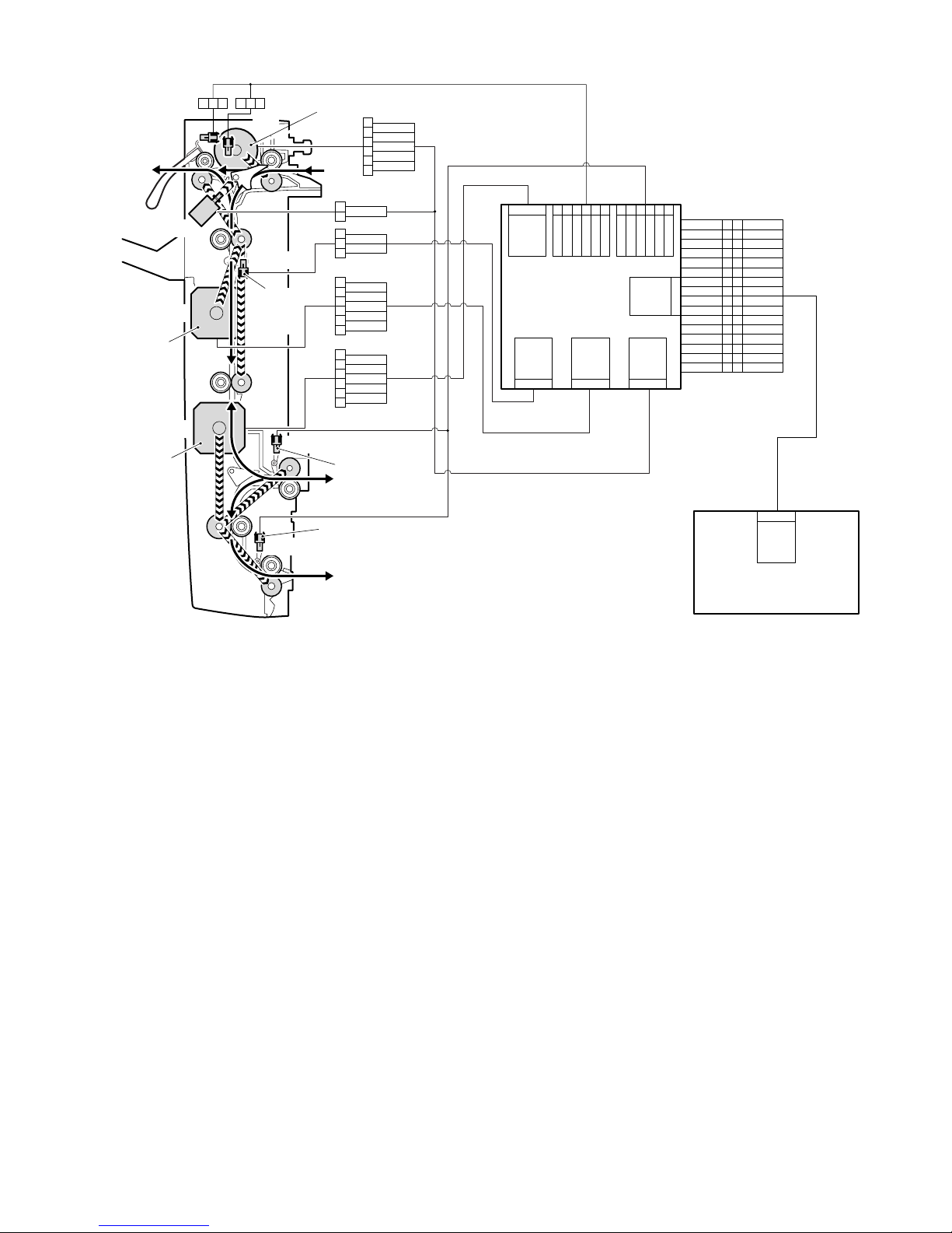
Unit: mm/s
Sensor input, motor output, solenoid output timing is as below.
Paper input motor
BPOD
BPPD1
BPRD
BPPD2
Upper turnover motor
Lower turnover motor
Paper kind Copier process
speed
RB1 tray delivery
speed
Thick paper 2 58.5 58.5
Envelope 117 117
OHP (priority: quality) 58.5 120
OHP (priority: speed) 117 160
Paper input roller
Delivery roller
BPOD
(Paper exit sensor)
BIM
(Paper-in motor)
BRM
(Upper reverse motor)
Process speed
BGSOL
(Gate solenoid)
Delivery speed
(Direction of
paper-in)
(Direction of
paper-out)