3
Chapter 2 Getting Started
This chapter describes the network scanning configuration procedures that dealer service or
customer MIS personnel need to perform prior to using Sharp’s network scanning system. Such
procedures involve three steps.
1. Password Setting
Setting up the administrator’s and user’s passwords for this software.
NOTE
The administrator of this software can set the passwords (for administrator and user) to authorize
the access to the Web pages such as E-mail Setup and Network Scanning Setup or Network
Scanner Management for the security of the settings on the pages. If such a security measure is
not required, the Password Setting procedure can be skipped. This will leave Web access
settings open to all users.
2. E-mail Setup and Network Scanning Setup
Configuration of the network scanning system and status & alert by E-mail.
3. Scanning Destination Setup
Setting the default scanning parameters on the device to send the scanned image or data as
Destinations.
NOTE
For the settings made by accessing the Web pages, such as E-mail Setup and Network Scanning
Setup, the following characters can not be input in the pages:
* Characters that cannot be input: < > & "
* Examples of improper input: <abc> <abc "abc" "abc abc" < >
The input is case-sensitive.
Password Setting
The administrator should exclusively do the setting of the password of two levels: User and Admin
when setting up network scanning system security. A User password is required to create, change,
and delete destinations. An Admin Password lets you access to the same functions as the User
password but is also required to set system configuration settings such as:
•Password Setup page
•E-mail Setup and Network Scanning Setup page
•Setup Status and Alerts by E-mail pages
When you first install your network scanning system, both password functions are disabled. To set a
User and/or Admin password the administrator is requested to follow the steps below:
1 Open the web browser such as Netscape Navigator 4.0 and later or Internet Explorer 4.0 and
later.
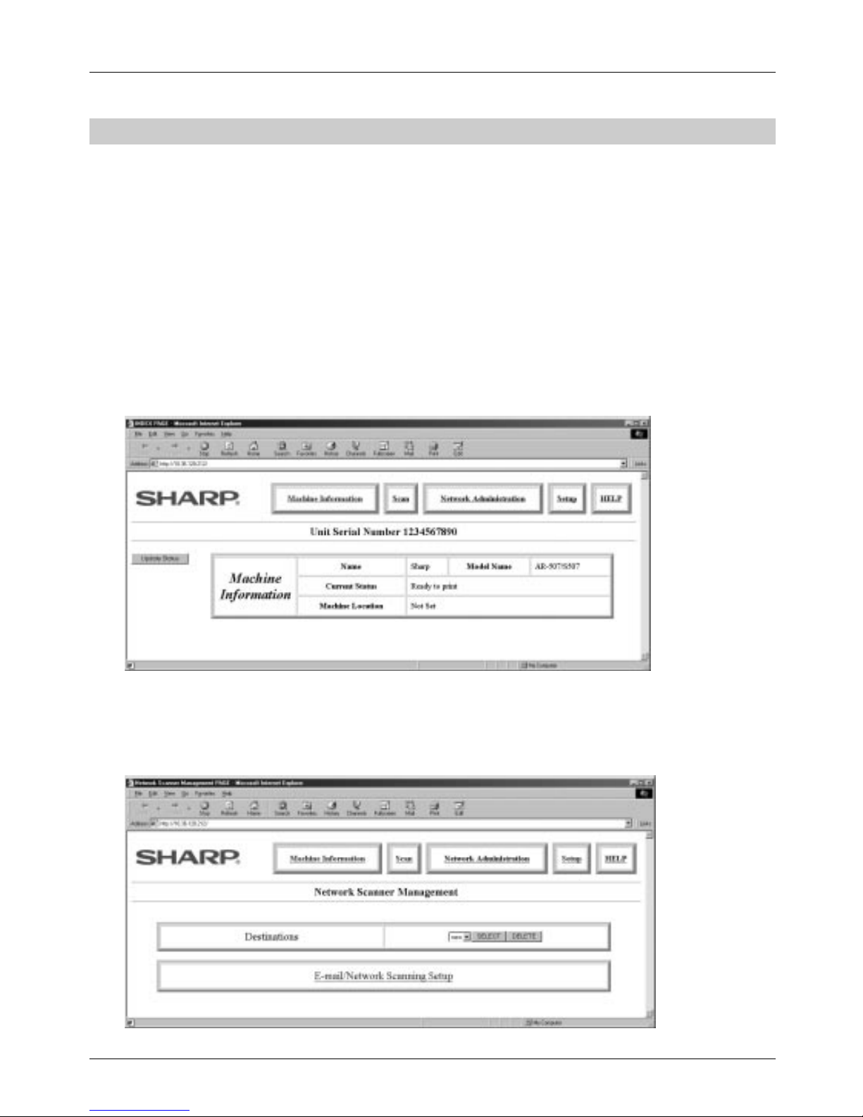
2 Input the IP Address previously specified to the ADDRESS field of the browser.
Input the IP address specified in the printer expansion kit AR-PB2A. (For checking the IP address, refer to
the part of “Identifying the Copier’s Network Address” on page 2.) When the connection is completed, the
Machine Information Page will be displayed.