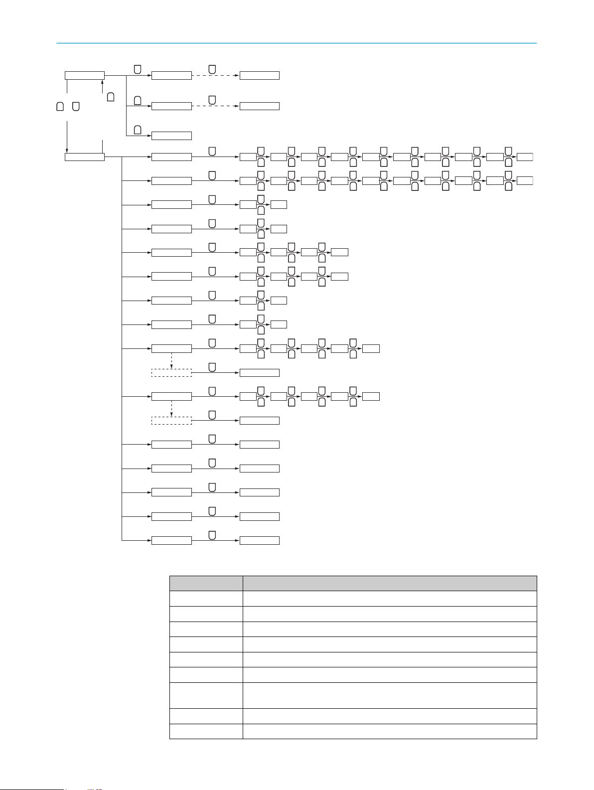
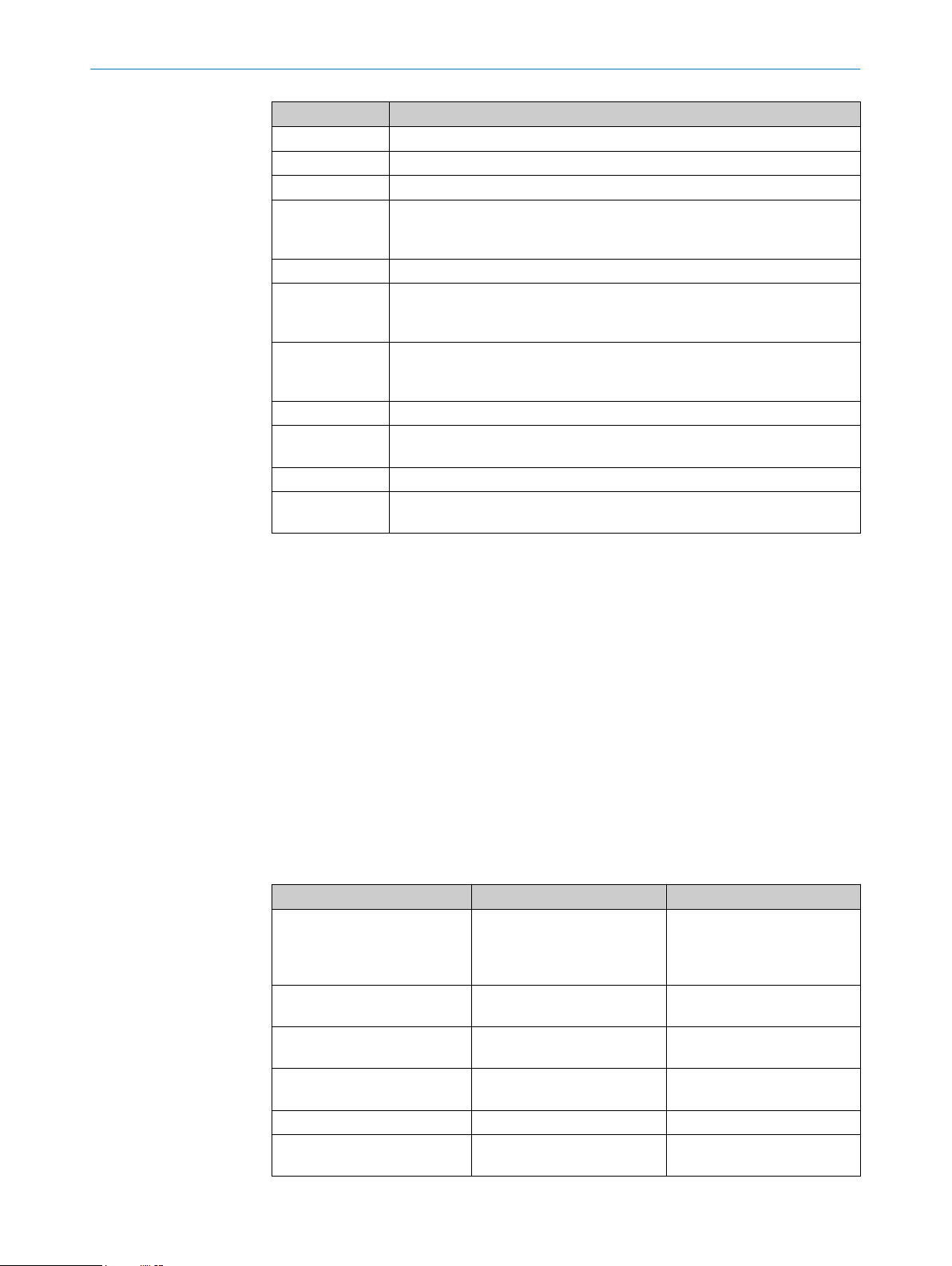
SICK WTT190LC-B2233A00 User manual

OPERATING INSTRUCTIONS
PowerProx Small Teach-in - WTT190LC-
B2233A00
MultiTask photoelectric sensor

Described product
PowerProx Small Teach-in – WTT190LC-B2233A00
Manufacturer
SICK AG
Erwin-Sick-Str. 1
79183 Waldkirch
Germany
Legal information
This work is protected by copyright. Any rights derived from the copyright shall be
reserved for SICK AG. Reproduction of this document or parts of this document is
only permissible within the limits of the legal determination of Copyright Law. Any modi‐
fication, abridgment or translation of this document is prohibited without the express
written permission of SICK AG.
The trademarks stated in this document are the property of their respective owner.
© SICK AG. All rights reserved.
Original document
This document is an original document of SICK AG.
44VC
2006/42/EC
NO
SAFETY
28024108.17AH / 04.02.2021 | SICK
Subject to change without notice

Contents
1 Safety information............................................................................ 4
1.1 General safety notes................................................................................ 4
1.2 Notes on UL approval............................................................................... 4
2 Product description........................................................................... 4
2.1 Intended use............................................................................................. 4
3 Commissioning.................................................................................. 5
3.1 Check the application conditions:........................................................... 5
3.2 Mounting................................................................................................... 5
3.3 Electronics................................................................................................. 5
3.4 Functioning of the programmable input.................................................. 6
3.5 Alignment.................................................................................................. 6
4 Configuration..................................................................................... 6
4.1 Setting the switching output via the teach-in quick access button
(-/Q1) (+/Q2)............................................................................................. 6
4.2 Additional functions.................................................................................. 7
4.3 Setting the switching outputs and other sensor configurations via the
menu......................................................................................................... 7
4.4 Pushbutton lock........................................................................................ 9
5 Troubleshooting................................................................................. 9
5.1 Troubleshooting........................................................................................ 9
5.2 Table: Fault diagnosis............................................................................... 9
6 Technical data.................................................................................... 10
6.1 Technical data........................................................................................... 10
6.2 Dimensional drawing................................................................................ 11
7 Disassembly and disposal............................................................... 11
8 Maintenance...................................................................................... 12
CONTENTS
8024108.17AH / 04.02.2021 | SICK
Subject to change without notice 3

1 Safety information
1.1 General safety notes
1.1.1 Safety notes
■Read the operating instructions before commissioning.
■Connection, mounting, and configuration may only be performed by trained spe‐
cialists.
■Not a safety component in accordance with the EU Machinery Directive.
■UL: Only for use in applications in accordance with NFPA 79. These devices must
be fused with a 1 A fuse that is suitable for 30 VDC. UL-listed adapters with
connecting cables are available.
■When commissioning, protect the device from moisture and contamination.
■These operating instructions contain information required during the life cycle of
the sensor.
EN/IEC 60825-1:2014
IEC60825-1:2007
Laser
1
Maximum pulse power < 64 mW
Puls length: 7 ns
Wavelength: 650 nm
Complies with 21 CFR 1040.10
and 1040.11 except for deviations
pursuant to Laser Notice No. 50,
dated June 24, 2007
LASER CLASS 1
ATTENTION
WARNING: Interruption, manipulation or incorrect use can lead to hazardous exposure
due to laser radiation.
1.2 Notes on UL approval
The device must be supplied by a Class 2 source of supply.
UL Environmental Rating: Enclosure type 1
2 Product description
2.1 Intended use
The PowerProx Small Teach-in - WTT190LC-B2233A00 is an opto-electronic photoelec‐
tric proximity sensor (referred to as “sensor” in the following) for the optical, non-con‐
tact detection of objects. If the product is used for any other purpose or modified in any
way, any warranty claim against SICK AG shall become void.
Photoelectric proximity sensor with background suppression and analog distance value
output.
1 SAFETY INFORMATION
48024108.17AH / 04.02.2021 | SICK
Subject to change without notice

3 Commissioning
3.1 Check the application conditions:
Check the application conditions: Adjust the sensing range and distance to the object
or background and the remission capability of the object according to the correspond‐
ing diagram [see H1, H2] (x = sensing range, y = minimum distance between the object
and background in mm (object remission / background remission)). Remission: 6% =
black, 90% = white (referring to standard white as per DIN 5033).
The minimum distance (= y) for background suppression can be read from diagram the
diagram [see H15] as follows:
Example: x = 1,000 mm, y = 20 mm. That is, the background is suppressed at a
distance of > 20 mm from the object.
200
(7.87)
180
(7.09)
160
(6.03)
120
(4.72)
80
(3.15)
40
(1.57)
140
(5.51)
100
(3.94)
60
(2.36)
20
(0.79)
0
Min. distance from object to background in mm (inch)
01,000
(39.37)
2,000
(78.74)
3,000
(118.11)
Distance in mm (inch)
1
2
3
4
5
6
7
8
9
ß
Figure: H-1 - Small teach and analog 6% / 90%
200
(7.87)
180
(7.09)
160
(6.03)
120
(4.72)
80
(3.15)
40
(1.57)
140
(5.51)
100
(3.94)
60
(2.36)
20
(0.79)
0
Min. distance from object to background in mm (inch)
01,000
(39.37)
2,000
(78.74)
3,000
(118.11)
Distance in mm (inch)
1
2
3
4
5
6
7
8
9
ß
Figure: H-2 - Small teach and analog 90% / 90%
3.2 Mounting
Mount the sensor using a suitable mounting bracket (see the SICK range of acces‐
sories).
Note the sensor's maximum permissible tightening torque of 0.8 Nm.
Note the preferred direction of the object relative to the sensor [F].
3.3 Electronics
The sensors must be connected in a voltage-free state (UV = 0 V). The information in
the graphics must be observed, depending on the connection type:
– Male connector connection: pin assignment
– Cable: Wire color
WTT190L
1 (brn) +12 - 24 VDC
1
2
4
3
2 (wht) Multi function input/output
3 (blu) GND
4 (blk) Switching output, IO-Link communication
COMMISSIONING 3
8024108.17AH / 04.02.2021 | SICK
Subject to change without notice 5

Only apply voltage/switch on the voltage supply (UV > 0 V) once all electrical connec‐
tions have been established. The green LED lights up on the sensor.
Explanations on connection diagram:
L+ = Supply voltage
MF = Programmable input or output
M = Ground
C/Q = Communication and switching output
3.4 Functioning of the programmable input
Function Minimum duration
Laser shutdown 4 ms
External teach-in Q1
External teach-in Q2 1 s
3.5 Alignment
Align the sensor with the object. Select the position so that the red emitted light beam
hits the center of the object. You must ensure that the optical opening (front screen)
of the sensor is completely clear [F]. We recommend making the adjustments using an
object with a low remission.
Figure: E
4 Configuration
Perform configuration:
4.1 Setting the switching output via the teach-in quick access button (-/Q1) (+/Q2)
The sensing range is adjusted by pressing the teach-in quick access button for > 1 s.
Do not operate the teach-in buttons using sharp objects. We recommend placing the
sensing range in the object, e.g., see Graphic F. Once the sensing range has been
adjusted, the object is removed from the path of the beam. This causes the background
to be suppressed and the switching output to change.
Sensing range settings via IO-Link. See IO-Link description (8022709).
The sensor is adjusted and ready for operation. Use the following graphic to check the
function. If the switching output fails to behave in accordance with the graphic, check
the application conditions. See section Fault diagnosis chapter 5.
3 COMMISSIONING
68024108.17AH / 04.02.2021 | SICK
Subject to change without notice

Figure: F
4.2 Additional functions
Table 1: Process data structure
Byte
offset Byte 0 Byte 1 Byte 2 Byte 3
Bit
offset 9 8 7 6 5 4 3 2 1 0
Distance
to object
Distance
to object Spare Value Qint.8 Qint.7 Qint.6 Qint.5 Qint.4 Qint.3 Qint.2 Qint.1 QL2 QL1
Integer
16
Integer
16
Unsigned
Integer 6 Boolean
Information on the IO-Link functions can be found in the IO-Link photoelectric sensors
operating instructions (available for download from www.sick.com under the device part
number).
4.3 Setting the switching outputs and other sensor configurations via the menu
As an alternative, the switching outputs can also be set via the menu. Further sensor
configurations can also be performed via the menu. The menu is accessed by briefly
pressing the Set button for < 1 s. Graphic K describes how to navigate within the menu.
NOTE
Entries qn1 and qn2 are only available when the accompanying teaching mode (qc1,
qc2) has been set to 2-point or window mode.
CONFIGURATION 4
8024108.17AH / 04.02.2021 | SICK
Subject to change without notice 7

–
Q1
+
Q2
–
Q1
+
Q2
–
Q1
+
Q2
–
Q1
+
Q2
–
Q1
+
Q2
–
Q1
+
Q2
–
Q1
+
Q2
–
Q1
+
Q2
–
Q1
+
Q2
–
Q1
+
Q2
–
Q1
+
Q2
–
Q1
+
Q2
–
Q1
+
Q2
–
Q1
+
Q2
–
Q1
+
Q2
–
Q1
+
Q2
–
Q1
+
Q2
–
Q1
+
Q2
–
Q1
+
Q2
–
Q1
+
Q2
–
Q1
+
Q2
–
Q1
+
Q2
–
Q1
+
Q2
–
Q1
+
Q2
–
Q1
+
Q2
–
Q1
+
Q2
–
Q1
+
Q2
–
Q1
+
Q2
–
Q1
+
Q2
–
Q1
+
Q2
–
Q1
+
Q2
–
Q1
+
Q2
–
Q1
+
Q2
–
Q1
+
Q2
–
Q1
+
Q2
–
Q1
+
Q2
SET
SET
SET
SET
SET
SET
SET
SET
SET
SET
SET
SET
SET
SET
SET
–
Q1
> 1 s
–
Q1
> 1 s
–
Q1
> 1 s
+
Q2
> 1 s
RUN
> 1 s
SP1 t11
SP1 t21
Loc uLc
MF
AVG
rSt
dSP
qc1
qc2
IL1
IL2
tL1
tL2
oFS
qF1
qn1 *
qn2 *
qF2
SP2 t12
SP2
no
oFF
-99 ... 100
20 ... 330
20 ... 330
20 ... 330
20 ... 330
no
no
no
no
oFF
1
no
no
t22
SET
Time 1 set 0 ... 999
SET
Time 2 set 0 ... 999
Ein LSr tch qn1qL2 qn2
2
yes
on
4 8
SPt WdW 2Pt
SPt WdW 2Pt
InV
InV
3216
ond oFd onF Sht
ond oFd onF Sht
64
qL1 qb1 coM
128 256 512
MENU mode
RUN mode
RUN SET
RUN
Press
or
SET
Press
or
wait >30 s
without
key entry
Figure 1: K
Menu item Function
“t11” / “t12” Teaches in switching threshold(s) SP1 or SP2 of switching point Qint.1
“t21” / “t22” Teaches in switching threshold(s) SP1 or SP2 of switching point Qint.2
“Loc” / “uLc” Locks / unlocks pushbuttons
“MF” Defines function of pin 2
“AVG” Moving average filter setting for measured value
“rSt” Resets all functions to factory settings
“dSP” Sets the display brightness (when the “off” value is selected, the display
dims 30 s after the last press of a button)
“qc1” Sets the switching mode for Qint.1
“qc2” Sets the switching mode for Qint.2
4 CONFIGURATION
88024108.17AH / 04.02.2021 | SICK
Subject to change without notice

Menu item Function
“IL1” Sets the inversion of signal output QL1 for the Smart Task
“IL2” Sets the inversion of signal output QL2 for the Smart Task
“tL1” Sets the delay function of output QL1
Time 1 setup Sets the delay time for output QL1. Can only be used when the delay
function is not deactivated. Note: In the case of a value that can only be
adjusted via IO-Link, the display shows “---”
“tl2” Sets the delay function of output QL2
Time 2 setup Sets the delay time for output QL2. Can only be used when the delay
function is not deactivated. Note: In the case of a value that can only be
adjusted via IO-Link, the display shows “---”
“oFs” Sets the offset value for the taught-in switching threshold (in mm). Note: In
the case of a value that can only be adjusted via IO-Link, the display shows
“---”
“qF1” Sets switching threshold SP1 for Qint.1 (in cm)
“qn1” Sets switching threshold SP2 for Qint.1 (in cm). Only available when the
“Window” / “two point” switching mode has been selected.
“qF2” Sets switching threshold SP1 for Qint.2 (in cm)
“qn2” Sets switching threshold SP2 for Qint.2 (in cm). Only available when the
“Window” / “two point” switching mode has been selected
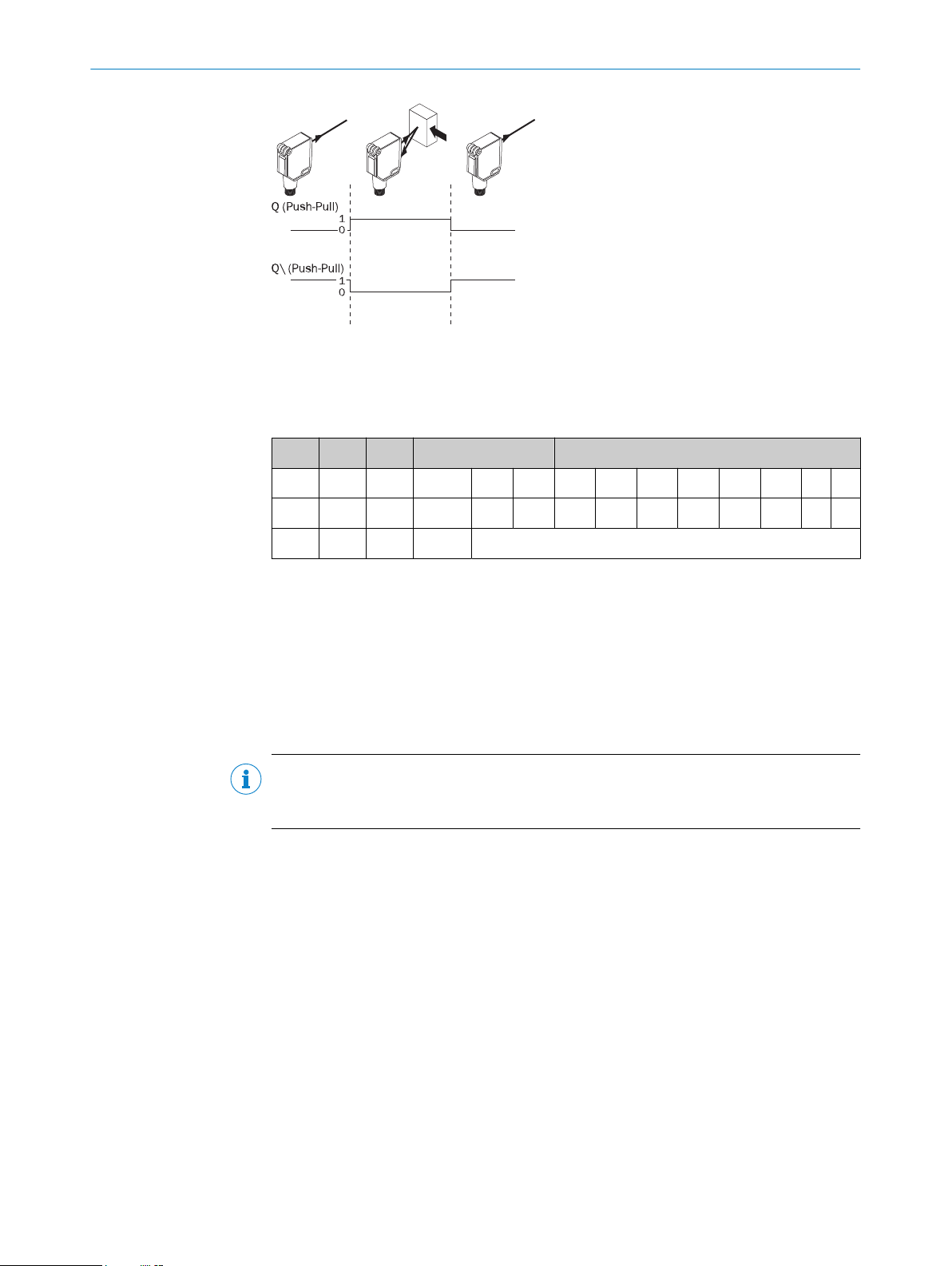
If the switching outputs are to be set via the menu, adjust the Q_X entries.
Press the Run button to leave the menu.
4.4 Pushbutton lock
Pushbutton lock on: Press the (Run) button for > 1 s
Pushbutton lock off: Press the (Run) button again for > 1 s
5 Troubleshooting
5.1 Troubleshooting
The Troubleshooting table indicates measures to be taken if the sensor stops working.
5.2 Table: Fault diagnosis
LED indicator/fault pattern Cause Measures
Green LED does not light up No voltage or voltage below
the limit values
Check the power supply,
check all electrical connec‐
tions (cables and plug connec‐
tions)
Green LED does not light up Voltage interruptions Ensure there is a stable power
supply without interruptions
Green LED does not light up Sensor is faulty If the power supply is OK,
replace the sensor
Green LED lights up, no output
signal when object is detected
Test input (Test) is not con‐
nected properly
See the note on connecting
the TI
Green LED flashes IO-Link communication -
Switching outputs not accord‐
ing to graphic F
IO-Link communication -
CONFIGURATION 4
8024108.17AH / 04.02.2021 | SICK
Subject to change without notice 9

LED indicator/fault pattern Cause Measures
Switching outputs not accord‐
ing to graphic F
Parameter settings made
manually, which deviate from
the standard
Initiate a factory reset. The
switching outputs are reset to
factory settings.
Yellow LEDs flash at the same
time
The sensor is not ready for
operation. The sensor will be
in the warming-up phase at
low ambient temperatures.
The sensor will have shut
down at excessively high
ambient temperatures.
At low ambient temperatures,
wait until the sensor has
warmed up. Ensure the sensor
cools down at excessively high
ambient temperatures.
Yellow LED flashes (only briefly) Teach-in mode Check the teach-in mode
Yellow LED lights up, no object
in the path of the beam
Distance between the sensor
and the background is too
short
Reduce the sensing range,
see graphic F
Object is in the path of the
beam, yellow LED does not
light up
Distance between the sensor
and the object is too long or
sensing range is set too short
Increase the sensing range,
see graphic F
6 Technical data
6.1 Technical data
WTT190LC-B2233
Laser class 1
Sensing range 0.2 ... 3.0 m 1)
Sensing range max. 0.2 ... 3.0 m 1)
Light spot diameter/distance < 12.0 mm / 3,0 m
Supply voltage UBDC 12 ... 30 V
Output current Imax. ≤ 100 mA
Switching frequency AVG 1: 833 Hz, AVG 4: 500 Hz, AVG
16: 147 Hz, AVG 64: 38 Hz, AVG
256: 10 Hz 2) 3)4)
Max. response time AVG 1: 0.6 ms, AVG 4: 1 ms, AVG 16:
3.4 ms, AVG 64: 13 ms, AVG 256:
51.4 ms 5) 3)4)
Enclosure rating IP67
Protection class III
Circuit protection A, B, C 6)
Ambient operating temperature -30 ... +50 °C7)
1) Tastgut mit 6 % ... 90 % Remission (bezogen auf Stan‐
dard-Weiß DIN 5033)
2) Mit Hell- / Dunkelverhältnis 1:1
3) Kann über Mittelwertfilter beeinflusst werden.
4) Abhängig von Abstand zu Objekt, Abstand zu Hinter‐
grund und gewählter Schaltschwelle
5) Signallaufzeit bei ohmscher Last
6) A = UB-Anschlüsse verpolsicher
B = Ein- und Ausgänge verpolsicher
C = Störimpulsunterdrückung
7) Bei Tu < -10°C: Aufwärmzeit < 10 min;UV>=24 V.
6 TECHNICAL DATA
10 8024108.17AH / 04.02.2021 | SICK
Subject to change without notice

6.2 Dimensional drawing
2
1
4 5
ß 9
6
7
8
3
4.8
(0.19)
28.3 (1.11)
17
(0.67) 32.8 (1.29)
9
(0.35)
16
(0.63)
44.4 (1.75)
39.2 (1.54)
2.6
(0.1)
3.7 (0.12)
1.2
(0.05)
1.9
(0.07)
Ø 3.1
(0.12)
7
(0.28)
6(0.24)
2.8 (0.11)
17.4 (0.69)
1Receiver
2Sender
3Connection
4RUN button
5(+/Q2) button
6Output display Q1 (orange)
7IO-Link communication (green)
8Output display Q2 (orange)
9(-/Q1) button
ßDisplay
à(SET) button
7 Disassembly and disposal
The sensor must be disposed of according to the applicable country-specific regula‐
tions. Efforts should be made during the disposal process to recycle the constituent
materials (particularly precious metals).
NOTE
Disposal of batteries, electric and electronic devices
•According to international directives, batteries, accumulators and electrical or
electronic devices must not be disposed of in general waste.
•The owner is obliged by law to return this devices at the end of their life to the
respective public collection points.
•
WEEE: This symbol on the product, its package or in this document,
indicates that a product is subject to these regulations.
TECHNICAL DATA 6
8024108.17AH / 04.02.2021 | SICK
Subject to change without notice 11

8 Maintenance
SICK sensors are maintenance-free.
We recommend doing the following regularly:
•Clean the external lens surfaces
•Check the screw connections and plug-in connections
No modifications may be made to devices.
Subject to change without notice. Specified product properties and technical data are
not written guarantees.
8 MAINTENANCE
12 8024108.17AH / 04.02.2021 | SICK
Subject to change without notice

Beschriebenes Produkt
PowerProx Small Teach-in - WTT190LC-B2233A00
Hersteller
SICK AG
Erwin-Sick-Str. 1
79183 Waldkirch
Deutschland
Rechtliche Hinweise
Dieses Werk ist urheberrechtlich geschützt. Die dadurch begründeten Rechte bleiben
bei der Firma SICK AG. Die Vervielfältigung des Werks oder von Teilen dieses Werks
ist nur in den Grenzen der gesetzlichen Bestimmungen des Urheberrechtsgesetzes
zulässig. Jede Änderung, Kürzung oder Übersetzung des Werks ohne ausdrückliche
schriftliche Zustimmung der Firma SICK AG ist untersagt.
Die in diesem Dokument genannten Marken sind Eigentum ihrer jeweiligen Inhaber.
© SICK AG. Alle Rechte vorbehalten.
Originaldokument
Dieses Dokument ist ein Originaldokument der SICK AG.
44VC
2006/42/EC
NO
SAFETY
14 8024108.17AH / 04.02.2021 | SICK
Subject to change without notice

Inhalt
9 Zu Ihrer Sicherheit............................................................................. 16
9.1 Allgemeine Sicherheitshinweise.............................................................. 16
9.2 Hinweise zur UL Zulassung...................................................................... 16
10 Produktbeschreibung....................................................................... 16
10.1 Bestimmungsgemäße Verwendung......................................................... 16
11 Inbetriebnahme................................................................................. 17
11.1 Einsatzbedingungen prüfen:.................................................................... 17
11.2 Montage.................................................................................................... 17
11.3 Elektronik.................................................................................................. 17
11.4 Funtionsweise des programmierbaren Eingangs................................... 18
11.5 Ausrichtung............................................................................................... 18
12 Konfiguration..................................................................................... 18
12.1 Einstellung des Schaltausgangs über die Teach-in-Schnellzugriffs‐
taste (-/Q1) (+/Q2)................................................................................... 18
12.2 Zusatzfunktionen...................................................................................... 19
12.3 Einstellung der Schaltausgänge sowie weitere Parametrierungen des
Sensors über das Menü........................................................................... 19
12.4 Tastensperre............................................................................................. 21
13 Störungsbehebung............................................................................ 21
13.1 Störungsbehebung................................................................................... 21
13.2 Tabelle Fehlerdiagnose............................................................................. 21
14 Technische Daten.............................................................................. 22
14.1 Technische Daten..................................................................................... 22
14.2 Maßzeichnung........................................................................................... 23
15 Demontage und Entsorgung............................................................ 23
16 Wartung.............................................................................................. 24
INHALT
8024108.17AH / 04.02.2021 | SICK
Subject to change without notice 15

9 Zu Ihrer Sicherheit
9.1 Allgemeine Sicherheitshinweise
9.1.1 Sicherheitshinweise
■Vor der Inbetriebnahme die Betriebsanleitung lesen.
■Anschluss, Montage und Einstellung nur durch Fachpersonal.
■Kein Sicherheitsbauteil gemäß EU-Maschinenrichtlinie.
■UL: Nur zur Verwendung in Anwendungen gemäß NFPA 79. Diese Geräte müssen
mit einer für 30V DC geeigneten 1A-Sicherung abgesichert werden. Von UL gelis‐
tete Adapter mit Anschlusskabeln sind verfügbar.
■Gerät bei Inbetriebnahme vor Feuchte und Verunreinigung schützen.
■Diese Betriebsanleitung enthält Informationen, die während des Lebenszyklus des
Sensors notwendig sind.
EN/IEC 60825-1:2014
IEC60825-1:2007
Laser
1
Maximale Pulsleistung: < 64 mW
Impulsdauer: 7 ns
Wellenlänge: 650 nm
Entspricht 21 CFR 1040.10
und 1040.11 mit Ausnahme von
Abweichungen nach
Laser-Hinweis 50, 24. Juni 2007
LASERKLASSE 1
ACHTUNG
ACHTUNG: Eingriffe oder Manipulationen oder nicht bestimmungsgemäße Verwendung
kann zu gefährlicher Belastung durch Laser-Lichtstrahlung führen.
9.2 Hinweise zur UL Zulassung
The device must be supplied by a Class 2 source of supply.
UL Environmental Rating: Enclosure type 1
10 Produktbeschreibung
10.1 Bestimmungsgemäße Verwendung
Die PowerProx Small Teach-in - WTT190LC-B2233A00 ist ein optoelektronischer Refle‐
xions-Lichttaster (im Folgenden Sensor genannt) und wird zum optischen, berührungs‐
losen Erfassen von Sachen eingesetzt. Bei jeder anderen Verwendung und bei Verände‐
rungen am Produkt verfällt jeglicher Gewährleistungsanspruch gegenüber der SICK AG.
Reflexionslichttaster mit Hintergrundausblendung.
9 ZU IHRER SICHERHEIT
16 8024108.17AH / 04.02.2021 | SICK
Subject to change without notice

11 Inbetriebnahme
11.1 Einsatzbedingungen prüfen:
Einsatzbedingungen prüfen: Schaltabstand und Distanz zum Objekt bzw. Hintergrund
sowie Remissionsvermögen des Objektes mit dem zugehörigen Diagramm [vgl. H1, H2]
abgleichen (x = Schaltabstand, y = Mindestabstand zwischen Objekt und Hintergrund in
mm (Remission Objekt / Remission Hintergrund)). Remission: 6 % = schwarz, 90 % =
weiß (bezogen auf Standardweiß nach DIN 5033).
Die minimale Distanz (= y) für die Hintergrundausblendung kann aus dem Diagramm
[vgl. H15] wie folgt abgelesen werden:
Beispiel: x = 1000 mm, y = 20 mm. D. h. der Hintergrund wird ab einer Distanz von >
20 mm vom Objekt ausgeblendet.
200
(7.87)
180
(7.09)
160
(6.03)
120
(4.72)
80
(3.15)
40
(1.57)
140
(5.51)
100
(3.94)
60
(2.36)
20
(0.79)
0
Min. distance from object to background in mm (inch)
01,000
(39.37)
2,000
(78.74)
3,000
(118.11)
Distance in mm (inch)
1
2
3
4
5
6
7
8
9
ß
Abbildung: H-1 - Small teach and analog
6%/90%
200
(7.87)
180
(7.09)
160
(6.03)
120
(4.72)
80
(3.15)
40
(1.57)
140
(5.51)
100
(3.94)
60
(2.36)
20
(0.79)
0
Min. distance from object to background in mm (inch)
01,000
(39.37)
2,000
(78.74)
3,000
(118.11)
Distance in mm (inch)
1
2
3
4
5
6
7
8
9
ß
Abbildung: H-2 - Small teach and analog
90%/90%
11.2 Montage
Den Sensor an einen geeigneten Befestigungswinkel montieren (siehe SICK-Zube‐
hör-Programm).
Maximal zulässiges Anzugsdrehmoment des Sensors von 0.8 Nm beachten.
Vorzugsrichtung des Objektes zum Sensor beachten [vgl. F].
11.3 Elektronik
Anschluss der Sensoren muss spannungsfrei (UV = 0 V) erfolgen. Je nach Anschlussart
sind die Informationen in den Grafiken zu beachten:
– Steckeranschluss: Pinbelegung
– Leitung: Adernfarbe
WTT190L
1 (brn) +12 - 24 VDC
1
2
4
3
2 (wht) Multi function input/output
3 (blu) GND
4 (blk) Switching output, IO-Link communication
INBETRIEBNAHME 11
8024108.17AH / 04.02.2021 | SICK
Subject to change without notice 17

Erst nach Anschluss aller elektrischen Verbindungen die Spannungsversorgung (UV > 0
V) anlegen bzw. einschalten. Am Sensor leuchtet die grüne Anzeige-LED.
Erläuterungen zum Anschlussschema:
L+ = Versorgungsspannung
MF = programmierbarer Ein- oder Ausgang
M = Masse
C/Q = Kommunikation und Schaltausgang
11.4 Funtionsweise des programmierbaren Eingangs
Funktion Minimale Dauer
Laserabschaltung 4 ms
Externer Teach Q1
Externer Teach Q2 1 s
11.5 Ausrichtung
Sensor auf Objekt ausrichten. Positionierung so wählen, dass der rote Sendelichtstrahl
in der Mitte des Objekts auftrifft. Es ist darauf zu achten, dass die optische Öffnung
(Frontscheibe) des Sensors vollständig frei ist [vgl. F]. Wir empfehlen, die Einstellung
mit einem Objekt von niedriger Remission vorzunehmen.
Abbildung: E
12 Konfiguration
Parametrierung durchführen:
12.1 Einstellung des Schaltausgangs über die Teach-in-Schnellzugriffstaste (-/Q1)
(+/Q2)
Durch Drücken der Teach-in-Schnellzugriffstaste > 1 s wird der Schaltabstand einge‐
stellt.
Teach-in-Tasten nicht mit spitzen Gegenständen betätigen. Wir empfehlen, den Schalt‐
abstand in das Objekt zu legen, z. B. siehe Grafik F. Nachdem der Schaltabstand
eingestellt worden ist, das Objekt aus dem Strahlengang entfernen. Der Hintergrund
wird dabei ausgeblendet und der Schaltausgang ändert sich.
Einstellungen des Schaltabstandes über IO-Link. Siehe IO-Link Beschreibung
(8021940).
11 INBETRIEBNAHME
18 8024108.17AH / 04.02.2021 | SICK
Subject to change without notice

Sensor ist eingestellt und betriebsbereit. Zur Überprüfung der Funktion die nachfol‐
gende Grafik heranziehen. Verhält sich der Schaltausgang nicht gemäß der nachfolgen‐
den Grafik, Einsatzbedingungen prüfen. Siehe Abschnitt Fehlerdiagnose in Kapitel 13.
Abbildung: F
12.2 Zusatzfunktionen
Tabelle 2: Prozessdatenstruktur
Byte-
Offset Byte 0 Byte 1 Byte 2 Byte 3
Bit-
Offset 9 8 7 6 5 4 3 2 1 0
Distance
to object
Distance
to object Spare Value Qint.8 Qint.7 Qint.6 Qint.5 Qint.4 Qint.3 Qint.2 Qint.1 QL2 QL1
Integer
16
Integer
16
Unsigned
Integer 6 Boolean
Die IO-Link Funktionalitäten der Betriebsanleitung IO-Link Photoelectric Sensors ent‐
nehmen (über www.sick.com unter der Geräte-Bestellnummer herunterladen).
12.3 Einstellung der Schaltausgänge sowie weitere Parametrierungen des Sensors über
das Menü
Die Schaltausgänge können alternativ auch über das Menü eingestellt werden. Ebenso
lassen sich weitere Parametrierungen des Sensors über das Menü vornehmen. Der
Zugriff zum Menü erfolgt über kurzes Drücken < 1 s der Taste Set. Die Navigation im
Menü beschreibt Grafik K.
HINWEIS
Die Einträge qn1 und qn2 sind nur verfügbar, wenn der dazugehörige Teach-Modus
(qc1, qc2) auf 2-Punkt oder Fenstermodus gesetzt wurde.
KONFIGURATION 12
8024108.17AH / 04.02.2021 | SICK
Subject to change without notice 19
Other manuals for WTT190LC-B2233A00
1
Table of contents
Languages:
Other SICK Accessories manuals

SICK
SICK WTB12L 1 Series User manual

SICK
SICK MultiPulse WTB4-3P2100S14 User manual

SICK
SICK WSE4F User manual

SICK
SICK JEF300 Manual

SICK
SICK SureSense HTB18L Series User manual

SICK
SICK GLS621 User manual

SICK
SICK PowerProx WTT12L User manual

SICK
SICK RFU61 Series User manual

SICK
SICK TiM4 Series User manual

SICK
SICK OD1000 User manual

SICK
SICK RAY26 User manual

SICK
SICK NAV310 User manual

SICK
SICK GRTE18S V Series User manual

SICK
SICK OL1 User manual

SICK
SICK WLA26 Series User manual

SICK
SICK GTE20 User manual

SICK
SICK LFV 330 User manual

SICK
SICK TiM1 Series User manual

SICK
SICK deTec4 C4C-EV03030A10000 User manual

SICK
SICK SureSense HTF18L User manual