nFUSE™ LED Lightbar
nFUSE Lightbar English 0520
5.
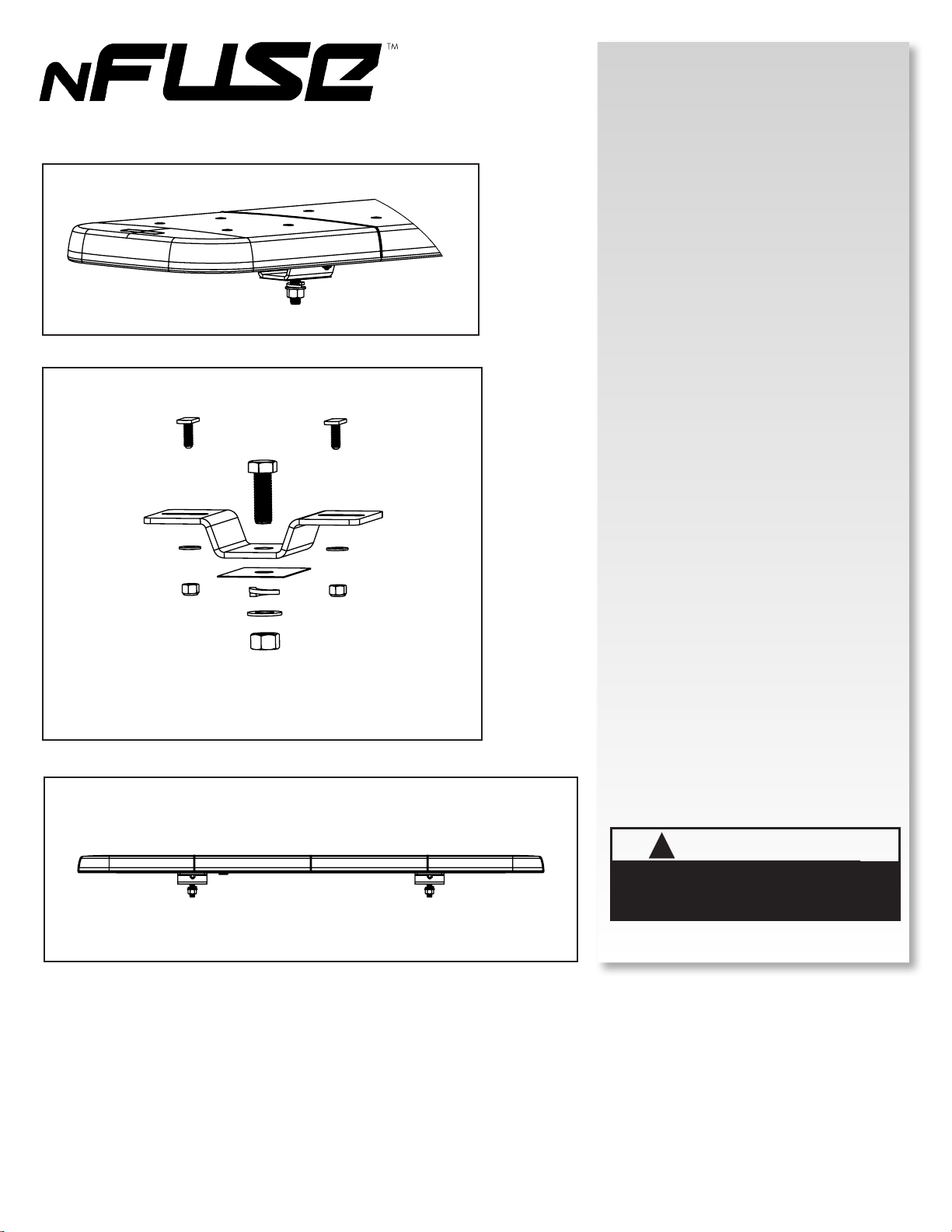
Figure 2.
Figure 3.
Figure 1.
HEADACHE RACK MOUNTING
(PNFLBK02)
1. Place the T-Slot bolts in the extrusion slots on the
underside of the lightbar.
2. Insert the ½” hex head bolt into the center hole of
the bracket.
3. Place the bracket on the T-Slot bolts and loosely
secure with at washers and nylon locking nuts.
4. Measure and drill appropriate sized holes on the
desired mounting surface, spaced evenly for
securing the lightbar.
5. Place the plastic spacer over each mounting hole.
6. Place lightbar and bracket assembly into the holes
and install the at washer, lock washer and hex nut
on the ½”hex bolt, tighten to compress lock washer.
(Torque may vary depending on the mounting
surface.)
7. Complete the installation by tightening the ¼-20
lock nuts to 40-60 in-lbs, DO NOT OVER TIGHTEN.
8. Follow the appropriate lightbar Owner’s Manual for
additional instructions and installation.
!
WARNING
Route wires only in locations that are not subjected to
potential wear. Make sure to avoid routing wires in the
deployment area of your air bag. Refer to your vehicle’s
owner’s manual for airbag deployment zone.
Headache Rack Mount
1. Place the T-Slot bolts in the extrusion slots
on the underside of the lightbar.
2. Insert the ½” hex head bolt into the center
hole of the bracket.
3. Place the bracket on the T-Slot bolts and
loosely secure with flat washers and nylon
locking nuts.
4. Measure and drill appropriate sized holes
on the desired moun�ng surface, spaced
evenly for securing the lightbar.
5. Place the plas�c spacer over each moun�ng
hole.
6. Place lightbar and bracket assembly into the
holes and install the flat washer, lock washer
and hex nut on the ½”hex bolt, �ghten to
compress lock washer. (Torque may vary
depending on the moun�ng surface).
7. Complete the installa�on by �ghtening the
¼-20 lock nuts to 40-60 in-lbs, DO NOT OVER
TIGHTEN.
8. Follow the appropriate lightbar Owner’s
Manual for addi�onal instruc�ons and
installa�on.
Permanent Mount
1. Place the T-Slot bolts in the extrusion
slots on the underside of the lightbar.
2. Place the bracket on the T-Slot bolts,
evenly space the brackets on the lightbar
and �ghten the ¼-20 lock nuts to 40-60
in-lbs, DO NOT OVER TIGHTEN.
3. Install the two rubber bumpers on the
bracket, rotate to lock into posi�on.
4. Mark the two inner holes on each
bracket to drill into the moun�ng
surface.
5. Fasten the hardware between the
lightbar and moun�ng surface.
6. Follow the appropriate lightbar
Owner’s Manual for addi�onal
instruc�ons and installa�on.
A A
B B
C C
D D
E E
F F
ENULBXXXXXXX
SHEET
PNFLBK02


 User manual")


 User manual")


