1.800.338.7337 / www.soundosignal.com
PMP2BK001 0320
2
6” OVAL MOUNTING KIT
FOR USE WITH MPOWER®3”, 4” STUD MOUNTS & 4x2 LIGHTS
PMP2BK001
NOTICE:
Installers and users must comply with all applicable federal, state and local laws regarding use and installation of warning devices.
Improper use or installation may void warranty coverage.
To review our Limited Warranty Statement & Return Policy for this or any SoundO Signal product, visit our website at www.soundosignal.com/tech-services/returns/.
If you have questions regarding this product, contact Technical Services, Monday - Friday, 8 a.m. to 5 p.m. ET at 1.800.338.7337 (press #4).
Questions or comments that do not require immediate attention may be emailed to techservices@soundosignal.com.
ENHANCING SAFETY THROUGH INNOVATION
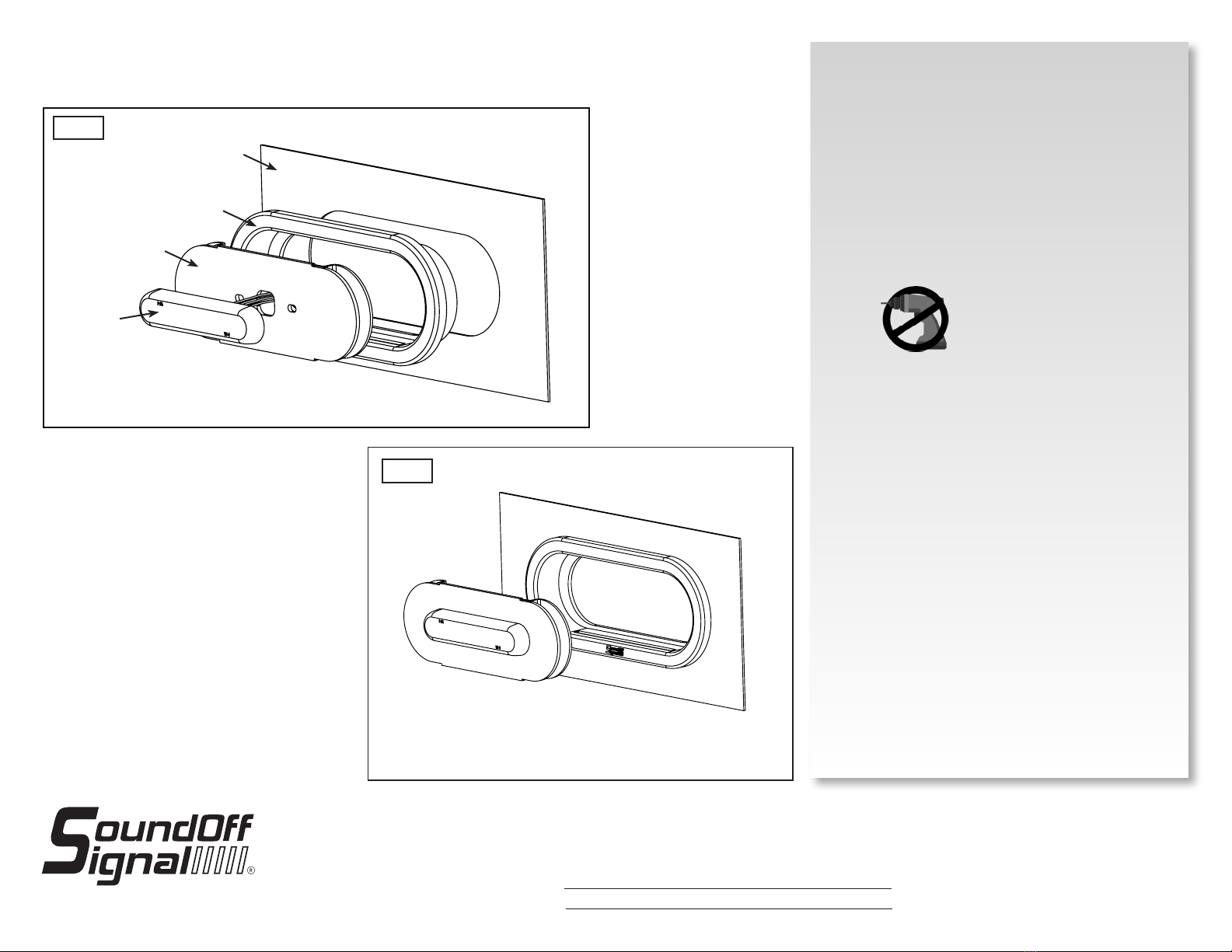
INSTALLATION:
1. Using the provided template* as a guide, mark and
cut an oval in the sheet metal in the desired location.
Ensure that any modications comply with the vehicle
manufacturer’s specications. It is recommended that
the cut edges be deburred and sealed prior to light
installation as necessary.
2. Feed the light module wires through the center hole and
attach a compatible, stud-mount mpower module to the
bracket as shown in Figure 3. Install 2 lock nuts onto the
studs behind the mount surface. After the nut makes full
contact with the mounting surface, hand tighten 1/8th
turn (torque no more than 15 in-lbs.)
3. Install the rubber grommet into the oval hole prior to
bracket installation, as shown in Figure 3. Ensure the
grommet is fully seated.
4. If access is limited, make necessary wire connections
before installing the bracket and light assembly.
5. Press bracket and light assembly into the grommet.
Ensure that the assembly is fully seated in the grommet.
PRIOR TO BRACKET INSTALLATION,
INSERT THE RUBBER GROMMET INTO THE OVAL HOLE
FIG. 3
DO NOT USE POWER
TOOLS TO TIGHTEN
FIGURE 1
FIGURE 3
REVISION LOG
REV
DESCRIPTION
INITIALS
ECN
DATE
1
01/01/1900
A A
B B
C C
D D
E E
F F
G G
H H
J J
10
10
9
9
8
8
7
7
6
6
5
5
4
4
3
3
2
2
1
1
PMP2BK001_ISHEET
MATERIAL:
THIRD ANGLE
PROJECTION
PROPRIETARY AND CONFIDENTIAL
THE INFORMATION CONTAINED IN
THIS DRAWING IS THE SOLE
PROPERTY OF SOUNDOFF SIGNAL.
ANY REPRODUCTION IN PART OR
AS A WHOLE WITHOUT THE
WRITTEN PERMISSION OF
SOUNDOFF SIGNAL IS PROHIBITED.
®
REVISION:
DESCRIPTION:
SHEET
1 OF 1
DRAWING
SIZE:
DO NOT SCALE
TOLERANCES
EXCEPT AS NOTED
.X ± .020
.XX ± .012
.XXX ± .006
ANGLES ± .5°
PRIMARY DIMS:
INCH
DUAL DIMS: [mm]
C
DRAWING NO:
GD&T TO FOLLOW
ASME Y14.5M-2009
CAD DIMENSIONS ARE BASIC
UNLESS OTHERWISE SPECIFIED
FIG. 2
MPOWER
(SOLD SEPARATELY)
SHEET METAL
GASKET
BRACKET
*The template is meant to only be a guide. It is the installer’s
responsibility to conrm the accuracy of the dimensions
provided and make adjustments as necessary.


 User manual")

 User manual")


