manuals.online logo
Brands
  1. Home
  2. •
  3. Brands
  4. •
  5. Soundoff Signal
  6. •
  7. Lighting Equipment
  8. •
  9. Soundoff Signal UltraLITE PLUS EL3PA12A00A User manual

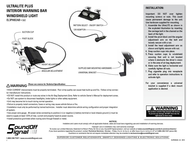
Soundoff Signal UltraLITE PLUS EL3PA12A00A User manual

EL3PA12A00A
EL3PA12A01A
EPL3PA12A0(X)A 0419
1.
UltraLITE PLUS
EXTERIOR LED DIRECTIONAL ARROW
NOTICE:
Installers and users must comply with all applicable federal, state and local laws regarding use and installation of warning devices. Improper use or installation may void
warranty coverage. To review our Limited Warranty Statement & Return Policy for this or any SoundOff Signal product, visit our website at www.soundoffsignal.com/sales-
support. If you have questions regarding this product, contact Technical Services, Monday - Friday, 8 a.m. to 5 p.m. or after hours 5 p.m. to 8 p.m. ET at 1.800.338.7337 (press #4
to skip the automated message). Questions or comments that do not require immediate attention may be emailed to [email protected].
SUPERIOR CUSTOMER RELATIONSHIPS. SMARTLY DESIGNED LIGHTING & ELECTRONIC SOLUTIONS.
1.800.338.7337 / www.soundoffsignal.com
TABLE OF CONTENTS
PAGE CONTENT
1 COMPONENTS/ CONTENTS
2 INSTALLATION INSTRUCTIONS/TECHNICAL
SPECIFICATIONS
3-4 ELECTRICAL INSTALLATION
5 FLASH PATTERNS
6 WARRANTY AND RETURN GOODS PROCEDURE
• Warning devices are strictly regulated and governed by Federal, State
and Municipal ordinances. These devices shall be used ONLY on approved
vehicles. It is the sole responsibility of the user of these devices to ensure
compliance.
• DO NOT install this product or route any wires in the Air Bag Deployment
Zone. Refer to your vehicle Owner’s Manual for the location of any air
bag deployment zones.
• DO NOT connect this device to a strobe power supply. This product is
self-contained and does not require an external power supply.
Important Information:
IMPORTANT NOTICE TO INSTALLER: Make sure to read and understand
all instructions and warnings before proceeding with the installation of this
product. Ensure that the manual and any warning cards are delivered to the
end user of this equipment. Proper installation of the lightbar requires the
installer to have a thorough knowledge of automotive electronics, systems,
and procedures. Lightbars provide an essential function of an effective visual
warning system. The use of the lightbar does not insure that all drivers can
or will abide by or react to an emergency warning signal, especially at high
rates of speeds or long distances. The operator of the vehicle must never take
the right of way for granted and it is the operator’s responsibility to proceed
safely. The effectiveness of the lightbar is highly dependant on the correct
mounting and wiring. The installer must read and follow the manufacturer’s
installation instructions and warnings in the manual. The vehicle operator
should verify daily that the lightbar is securely fastened to the vehicle and
properly functioning before operating vehicle. The lightbar is intended for use
by authorized personnel only. It is the user’s responsibility to ensure they
understand and operate the emergency warning devices in compliance with
the applicable city, state and federal laws and regulations. SoundOff Signal
assumes no liability for any loss resulting from the use of this warning device.
!
WARNING
This product contains high intensity LED devices.
To prevent eye damage, DO NOT stare into the
light beam at close range.
EL3PA12A00A
EL3PA12A01A
EPL3PA12A0(X)A 0419
2.
UltraLITE PLUS
EXTERIOR LED DIRECTIONAL ARROW
NOTICE:
Installers and users must comply with all applicable federal, state and local laws regarding use and installation of warning devices. Improper use or installation may void
warranty coverage. To review our Limited Warranty Statement & Return Policy for this or any SoundOff Signal product, visit our website at www.soundoffsignal.com/sales-
support. If you have questions regarding this product, contact Technical Services, Monday - Friday, 8 a.m. to 5 p.m. or after hours 5 p.m. to 8 p.m. ET at 1.800.338.7337 (press #4
to skip the automated message). Questions or comments that do not require immediate attention may be emailed to [email protected].
SUPERIOR CUSTOMER RELATIONSHIPS. SMARTLY DESIGNED LIGHTING & ELECTRONIC SOLUTIONS.
!
WARNING
This product contains high intensity LED devices.
To prevent eye damage, DO NOT stare into the
light beam at close range.
INSTALLATION
MOUNTING INSTRUCTIONS
1. Mark 11.5" from the top point on the back rack.
2. Attach the bracket to the back rack by drilling in the (4) self-
tapping screws to the designated location.
3. Thread the nuts onto the T-bolts about 3 thread lengths; make
sure there is enough thread left to slide the arrow onto the bracket.
4. Align the T-bolts with the slots on the brackets attached to the
back rack. Slide the T-bolts into the slotted holes.
5. While the nuts are still loose, slide the arrown back and forth until
the arrow is centered on the back rack.
6. Tighten down the T-bolts using a 3/8" wrench.
7. Plug in the harness to the arrow.
POWER SPECIFICATIONS
Input Voltage
Range:
10 -16 Vdc
Current Draw
10 Amps Peak, 5 Amp
Avg. w/50% Duty Cycle
Flash Pattern. ~60 Watt Avg.
Standby Current
<0.0002 Amps <0.0025 Watts
Reverse Polarity
Protected
Load Dump
Protected
Wiring
Power Cable 15ft 12 AWG Wires,
(+) Red, (-) Black
Control Wires: 6x 22AWG 15ft
TECHNICAL SPECIFICATIONS
Material: Anodized Extruded
Aluminum
Dimensions: 51.75"L x 21.5"H x 1.5" D
Operating Temperature: -40º to +85º C
Pattern Selection
Because of the variety of conguring options, see separate
sheets for detailed instructions.
NOTE: The brackets being screwed into the
back rack cannot be more than 35" apart.
NOTE: Arrow should be mounted with wire on
Driver Side.
EL3PA12A00A
EL3PA12A01A
EPL3PA12A0(X)A 0419
3.
UltraLITE PLUS
EXTERIOR LED DIRECTIONAL ARROW
NOTICE:
Installers and users must comply with all applicable federal, state and local laws regarding use and installation of warning devices. Improper use or installation may void
warranty coverage. To review our Limited Warranty Statement & Return Policy for this or any SoundOff Signal product, visit our website at www.soundoffsignal.com/sales-
support. If you have questions regarding this product, contact Technical Services, Monday - Friday, 8 a.m. to 5 p.m. or after hours 5 p.m. to 8 p.m. ET at 1.800.338.7337 (press #4
to skip the automated message). Questions or comments that do not require immediate attention may be emailed to [email protected].
SUPERIOR CUSTOMER RELATIONSHIPS. SMARTLY DESIGNED LIGHTING & ELECTRONIC SOLUTIONS.
ELECTRICAL INSTALLATION
Featured Highlights & Terminology:
Power Cable:
1. Route lightbar power cables as close to vehicles power source (battery) as possible.
2. Install a maximum of 15 Amp Fuse (customer supplied) to the end of the RED wire of the Lightbar Power Cable.
a. Remove the fuse before connecting any wires to the battery.
b. DO NOT USE CIRCUIT BREAKER OR FUSIBLE LINK.
3. Connect the other end of the Fuse to the POSITIVE (+) terminal of the battery or other high current source.
a. Do NOT use any more than 2ft of wire between the power source and the fuse and ensure the wire is
protected and secured from being cut into; this is non-fused wire.
4. Connect the BLACK wire to the factory chassis ground right next to the battery or other ground location capable of handling
high current.
Low Current Standby Mode (reduced standby current)
If there is no active input the lightbar will go into a “standby” mode. The standby mode is a very low power mode that is used to extend the life of
your battery. The lightbar will awaken from the standby mode if any input is activated.
Over-Voltage Protection
When an over-voltage condition of ≥18.0Vdc is detected, the module will ash an over-voltage warning pattern of 50mS ON/950mS OFF to alert of
the over-voltage condition and protect the electronics from damage due to heat/voltage.
WIRING
Input
#
Wire
Color Gauge Activated Function
1 RED 12AWG Full Time +12V
2BLACK 12AWG Ground
3 ORANGE 22AWG (+) Warning Mode 1 Warning Mode 3.
When ORG & BLU
wire are active.
4BLUE 22AWG (+) Front, Warning Mode 2
5RED/
WHITE 22AWG (+) Left Arrow Center Out Arrow
when RED/WHITE and
BROWN/WHITE wires
are both activated
6BROWN/
WHITE 22AWG (+) Right Arrow
7 GREEN 22AWG
Low Power, Intensity Control
ALL lights in ALL activated Modes dim to minimize blinding effects of ap-
proaching drivers.
8 BROWN 22AWG Pattern Select
9YELLOW 22AWG Factory Use Only
EL3PA12A00A
EL3PA12A01A
EPL3PA12A0(X)A 0419
4.
UltraLITE PLUS
EXTERIOR LED DIRECTIONAL ARROW
NOTICE:
Installers and users must comply with all applicable federal, state and local laws regarding use and installation of warning devices. Improper use or installation may void
warranty coverage. To review our Limited Warranty Statement & Return Policy for this or any SoundOff Signal product, visit our website at www.soundoffsignal.com/sales-
support. If you have questions regarding this product, contact Technical Services, Monday - Friday, 8 a.m. to 5 p.m. or after hours 5 p.m. to 8 p.m. ET at 1.800.338.7337 (press #4
to skip the automated message). Questions or comments that do not require immediate attention may be emailed to [email protected].
SUPERIOR CUSTOMER RELATIONSHIPS. SMARTLY DESIGNED LIGHTING & ELECTRONIC SOLUTIONS.
ELECTRICAL INSTALLATION (CONTINUED)

a. Apply voltage to the activation wire(s) of the warning function which requires pattern to be changed (i.e. Warning Mode1, 2 or 3).
b. Momentarily connect the pattern select wire to ground to change the pattern. The pattern is changed when pattern select is disconnected per
the Setup Table below.

a. Apply voltage to the activation wire(s) of the Arrow function which requires pattern to be changed (i.e. Arrow Mode Left, Right or Center Out).
b. Momentarily connect to the pattern select wire to ground to change the pattern. The pattern is changed when pattern select is disconnected per
the Setup Table below.

changed when the bar is active.
SETUP TABLE
SECONDS
USER INTERFACE
TIME OUTPUT ACTION TAKEN COMMENTS
Debounce to ≤1 sec
All modules turn to Steady High
Advance 1 Pattern
1 to ≤2 sec
All modules turn to Steady Low
Reverse 1 Pattern
2 to ≤3 sec
All modules turn OFF
Reset to Default Resets Active Wires to
Default
3 to ∞ sec Normal warning pattern will resume No action taken. No
pattern change will occur.
Note: No pattern change will occur if pattern select is active for more than 3 seconds. Normal warning pattern
will resume. New patterns will start to ash immediately if the pattern select wire is released during a valid
conguration time.
RED
BLACK
ORANGE
BLUE
RED/WHITE
BROWN/WHITE
GREEN
BROWN
+Vdc
EXTERIOR LED DIRECTIONAL ARROW
10A FUSE
EL3PA12A00A
EL3PA12A01A
EPL3PA12A0(X)A 0419
5.
UltraLITE PLUS
EXTERIOR LED DIRECTIONAL ARROW
NOTICE:
Installers and users must comply with all applicable federal, state and local laws regarding use and installation of warning devices. Improper use or installation may void
warranty coverage. To review our Limited Warranty Statement & Return Policy for this or any SoundOff Signal product, visit our website at www.soundoffsignal.com/sales-
support. If you have questions regarding this product, contact Technical Services, Monday - Friday, 8 a.m. to 5 p.m. or after hours 5 p.m. to 8 p.m. ET at 1.800.338.7337 (press #4
to skip the automated message). Questions or comments that do not require immediate attention may be emailed to [email protected].
SUPERIOR CUSTOMER RELATIONSHIPS. SMARTLY DESIGNED LIGHTING & ELECTRONIC SOLUTIONS.
*fpm=Flashes per Minute
**fps=Flashes per Second
WARNING FLASH PATTERNS
# Name
SAE
Compliant
Timing
CA Sequence fpm* fps**
1RandomAction 1 Yes -Random - -
2RandomAction 2 - - Random - -
3RandomAction 3 - - Random - -
4RandomAction 4 -Yes Random - -
5Quint Yes -Variable 67 1.1
6Quad2 Yes -Variable 67 1.1
7Q-Switch™ Yes -Variable - -
8 Double2 Yes -Variable 115 1.9
9 Power Pulse Yes -Variable 188 3.1
10 Road Runner Yes Yes Variable 115 1.9
11 Slow Runner Yes Yes Variable 70 1.2
12 Warp - - Variable 333 5.6
13 Intercycle - - Variable 67 & 333 1.1 & 5.6
14 Warp 1, 2, 3 - - Variable 115 - 333 1.9 - 5.6
15 OFF - - OFF - -
Mode Pattern #
(Name)
Warning Mode 1, 2, 3 RandomAction 1
Arrow Mode L, C & R Single Fast
DEFAULT PATTERNS
ARROW FLASH PATTERNS
# Name
SAE
Compliant
Timing
CA Sequence fpm* fps**
1Single Fast - - - - -
2Single Slow - - - - -
3Chaser Fast - - - - -
4Chaser Slow - - - - -
5Fill Fast - - - - -
6Fill Slow - - - - -
7Grow/Shrink - - - - -
EL3PA12A00A
EL3PA12A01A
EPL3PA12A0(X)A 0419
6.
UltraLITE PLUS
EXTERIOR LED DIRECTIONAL ARROW
NOTICE:
Installers and users must comply with all applicable federal, state and local laws regarding use and installation of warning devices. Improper use or installation may void
warranty coverage. To review our Limited Warranty Statement & Return Policy for this or any SoundOff Signal product, visit our website at www.soundoffsignal.com/sales-
support. If you have questions regarding this product, contact Technical Services, Monday - Friday, 8 a.m. to 5 p.m. or after hours 5 p.m. to 8 p.m. ET at 1.800.338.7337 (press #4
to skip the automated message). Questions or comments that do not require immediate attention may be emailed to [email protected].
SUPERIOR CUSTOMER RELATIONSHIPS. SMARTLY DESIGNED LIGHTING & ELECTRONIC SOLUTIONS.

A review of bolt/hardware/mounting bracket integrity should be performed
at the beginning and end of each shift.
WARNING - DRILLING ANY HOLES INTO THE LIGHTBAR IS NOT
RECOMMENDED! THE RISK OF DAMAGING INTERNAL COMPONENTS
AND THE RESULTING FAILURE OF THE LIGHTBAR WILL VOID ANY
WARRANTY OF THIS PRODUCT.
WARNING - CARE MUST BE TAKEN WHEN DRILLING THROUGH
THE ROOF OF THE VEHICLE NOT TO DRILL INTO ANY EXISTING
WIRING AND NOT TO DRILL THROUGH THE HEADLINER OR SUPPORT
MEMBERS OF THE VEHICLE. CHECK BOTH SIDES OF THE MOUNTING
SERVICE PRIOR TO DRILLING. DE-BURR ANY HOLES AND REMOVE
ANY METAL SHARDS OR REMNANTS. INSTALL GROMMETS INTO
ALL WIRE PASSAGE HOLES.
WARNING - ROUTE WIRES ONLY IN LOCATIONS THAT ARE NOT
SUBJECTED TO POTENTIAL WEAR. MAKE SURE TO AVOID ROUTING
WIRES IN THE DEPLOYMENT AREA OF YOUR AIR BAG. REFER TO
YOUR VEHICLE OWNER’S MANUAL FOR AIR BAG DEPLOYMENT
ZONES.
WARNING - ALL CUSTOMER SUPPLIED POWER WIRES CONNECTING
TO THE POSITIVE (+) OR NEGATIVE (-) BATTERY TERMINAL OR
LOCAL CHASSIS GROUND (-) MUST BE SIZED TO SUPPLY AT LEAST
125% OF THE MAXIMUM CURRENT AND PROPERLY FUSED AT THE
POWER SOURCE WITH APPROPRIATELY RATED FUSE.
IMPORTANT: When passing cables through re wall or other sheet
metal, insert grommet to protect the cable!
:
Please contact your SoundOff Signal Sales Representative, Customer Services
staff or our Technical Department (800.338.7337) for a RMA #, Return
Merchandise Authorization Number.
The following information is required for issuance of the RMA #:
• Reason for returning the product*
• Address where replacement product is to be shipped*
• Telephone number where you may be reached*
• SoundOff Signal invoice number on which product was purchased**
• SoundOff Signal part number and serial number**
• E-mail address where RMA # should be e-mailed**
• Fax number where RMA # should be faxed**
* RMA # will not be given without this information.
** If available, please provide this information.
SoundOff Signal will NOT accept returns without an RMA #. Each RMA #
is good for only one (1) return and will expire (30) days after the date it was
issued. Products must be shipped back to SoundOff Signal and the RMA #
clearly marked on the outside of the package near the shipping label. Please
use the following address on your shipping label:
SoundOff Signal
ATTN: RMA # / Technical Services
3900 Central Parkway
Hudsonville, MI 49426

Shipping & Handling, labor and service fees are non-refundable. SoundOff
Signal is not liable for any damage due to installation or personal injury as a
result of using SoundOff Signal product.

Warranty will not be granted if the Warranty Return Policy & Procedure rules
are not strictly followed. Physical damage resulting from customer abuse
will void warranty. Warranty will also be voided if any SoundOff Signal and/
or manufacturer serial tags, product stickers, seals, or the like, are removed,
altered or tampered with. Returned product that is damaged by shipping via
the RMA # procedure is not the responsibility of SoundOff Signal.
Document effective date on cover and below supersedes previously dated
policies and statements.
There are no other warranties, expressed or implied, including, but not limited
to, any implied merchantability or tness for a particular use. SoundOff
Signal reserves the right to modify this warranty statement at any time; or to
discontinue, modify, or upgrade any products of its manufacture with design
improvements without prior notice.
WARNING MESSAGES - PLEASE READ:


This manual suits for next models

1

Other Soundoff Signal Lighting Equipment manuals

Soundoff Signal Pinnacle EPL7000 Series User manual

Soundoff Signal

Soundoff Signal Pinnacle EPL7000 Series User manual

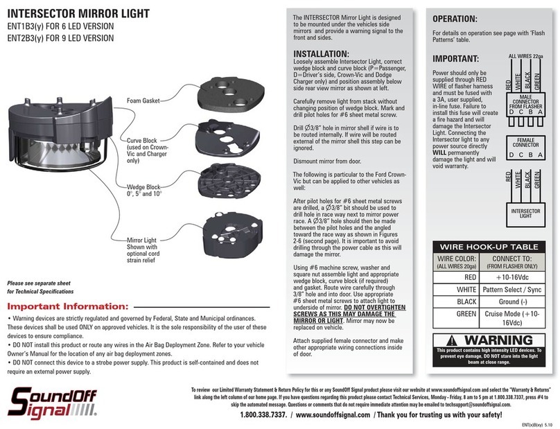
Soundoff Signal ENT1B3(y) User manual

Soundoff Signal

Soundoff Signal ENT1B3(y) User manual

Soundoff Signal BOLT2 User manual

Soundoff Signal

Soundoff Signal BOLT2 User manual

Soundoff Signal P Series User manual

Soundoff Signal

Soundoff Signal P Series User manual

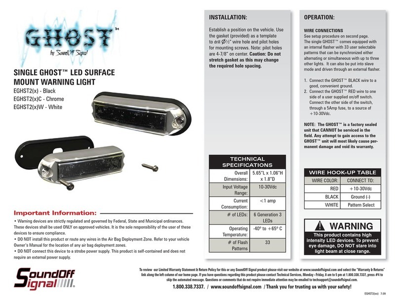
Soundoff Signal SINGLE GHOST EGHST2 User manual

Soundoff Signal

Soundoff Signal SINGLE GHOST EGHST2 User manual

Soundoff Signal PINNACLE Mini Lightbar User manual

Soundoff Signal

Soundoff Signal PINNACLE Mini Lightbar User manual

Soundoff Signal EFL1 5 Series User manual

Soundoff Signal

Soundoff Signal EFL1 5 Series User manual

Soundoff Signal P Series User manual

Soundoff Signal

Soundoff Signal P Series User manual

Soundoff Signal MPOWER EMPS2QM Series User manual

Soundoff Signal

Soundoff Signal MPOWER EMPS2QM Series User manual

Soundoff Signal NEXUS TECHNOLOGY nFORCE LED Lightbar 24 User manual

Soundoff Signal

Soundoff Signal NEXUS TECHNOLOGY nFORCE LED Lightbar 24 User manual

Soundoff Signal mPower EMPR10004-WW User manual

Soundoff Signal

Soundoff Signal mPower EMPR10004-WW User manual

Soundoff Signal UltraLite EL3D02A00(x) User manual

Soundoff Signal

Soundoff Signal UltraLite EL3D02A00(x) User manual

Soundoff Signal P Series User manual

Soundoff Signal

Soundoff Signal P Series User manual

Soundoff Signal FR100 Series User manual

Soundoff Signal

Soundoff Signal FR100 Series User manual

Soundoff Signal MPower EMPR10004-WW User manual

Soundoff Signal

Soundoff Signal MPower EMPR10004-WW User manual

Soundoff Signal PMP2BK001 User manual

Soundoff Signal

Soundoff Signal PMP2BK001 User manual

Soundoff Signal Intersector ENT3 3 Series User manual

Soundoff Signal

Soundoff Signal Intersector ENT3 3 Series User manual

Soundoff Signal PREDATOR II User manual

Soundoff Signal

Soundoff Signal PREDATOR II User manual

Soundoff Signal LED3 MINI LIGHT EL3SN Series User manual

Soundoff Signal

Soundoff Signal LED3 MINI LIGHT EL3SN Series User manual

Soundoff Signal P Series User manual

Soundoff Signal

Soundoff Signal P Series User manual

Soundoff Signal P Series User manual

Soundoff Signal

Soundoff Signal P Series User manual

Soundoff Signal nFUSE User manual

Soundoff Signal

Soundoff Signal nFUSE User manual

Soundoff Signal ULTRALITE PLUS User manual

Soundoff Signal

Soundoff Signal ULTRALITE PLUS User manual

Popular Lighting Equipment manuals by other brands

Cateye TIGHT KINETIC TL-LD180K manual

Cateye

Cateye TIGHT KINETIC TL-LD180K manual

Cooper WaveLinx Wireless Wallstation installation guide

Cooper

Cooper WaveLinx Wireless Wallstation installation guide

Sammode L10 MAXWELL SUB-ZERO MAINTAINED 184190 Installation & maintenance

Sammode

Sammode L10 MAXWELL SUB-ZERO MAINTAINED 184190 Installation & maintenance

Welch Allyn XENON 300 Operating instructions manual

Welch Allyn

Welch Allyn XENON 300 Operating instructions manual

CALIVE TITAN I installation guide

CALIVE

CALIVE TITAN I installation guide

Ehrgeiz Fusion FS-80 RGBW/1 operating manual

Ehrgeiz

Ehrgeiz Fusion FS-80 RGBW/1 operating manual

eldoLED LINEARdrive 100/A Tech sheet

eldoLED

eldoLED LINEARdrive 100/A Tech sheet

RZB Lighting light control +3 instructions

RZB Lighting

RZB Lighting light control +3 instructions

Altman AST-9000-UL4-ST2 Series Application guide

Altman

Altman AST-9000-UL4-ST2 Series Application guide

Vision & Control LDLF30x540-G525/24V/-a Instructions for use

Vision & Control

Vision & Control LDLF30x540-G525/24V/-a Instructions for use

BADU JET Perla translation of original operation manual

BADU

BADU JET Perla translation of original operation manual

COP Security 15-IL3810 user manual

COP Security

COP Security 15-IL3810 user manual

Vision & Control DL30x30-B470/UDC/-a Instructions for use

Vision & Control

Vision & Control DL30x30-B470/UDC/-a Instructions for use

Chauvet 4Play user manual

Chauvet

Chauvet 4Play user manual

MJ LED LIGHTNING MJ-1350 user manual

MJ LED LIGHTNING

MJ LED LIGHTNING MJ-1350 user manual

Osram SYNIOS P2720 Series Application note

Osram

Osram SYNIOS P2720 Series Application note

Acolyte NEONLYTE installation manual

Acolyte

Acolyte NEONLYTE installation manual

Traxxas Pro Scale 9784 installation instructions

Traxxas

Traxxas Pro Scale 9784 installation instructions

manuals.online logo
manuals.online logoBrands
  • About & Mission
  • Contact us
  • Privacy Policy
  • Terms and Conditions

Copyright 2025 Manuals.Online. All Rights Reserved.