V210809
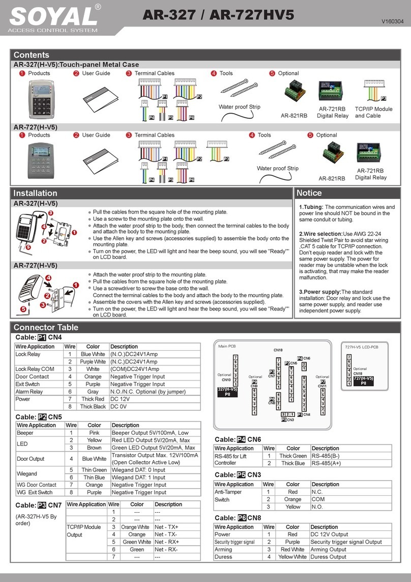
EXIT
N.C.
N.O.
COM
CTL
12V
GND
PB
12V
GND
12V
GND
N.O.
12V
GND
12V
GND
DDR
CN4
CN8
CN2
AR-721RB
12V
327-E
727-E
1
2
3
4
5
6
7
8
1 2 3 4
7
6
5
4
3
2
1CN18
727-E
727-E
LCD-PCB
7
6
5
4
3
2
1
327-E
CN18
N.C.
N.O.
COM
CTL
12V
E
BZ
RLED
GLED
WG 1
12V
GND
1
2
3
6
12V
GND
Exit Switch
12V
GND
CN5
CN4
BZ
RLED
GLED
Door Output
WG 0
WG 1
WG-DS
WG-PB
7
8
N.C.
EXIT
1
2
3
4
5
6
7
8
5
4
WG 0
7
6
5
4
3
2
1CN18
727-E
727-E
LCD-PCB
7
6
5
4
3
2
1
327-E
CN18
WG Port
WG Port
WG Port
WG Port
Main Port
Main Port
LCD Access Controller
RTE
Controller
Controller
Reader
RTE
POWER
12VDC
POWER
12VDC
POWER
12VDC
POWER
12VDC
Door Contact
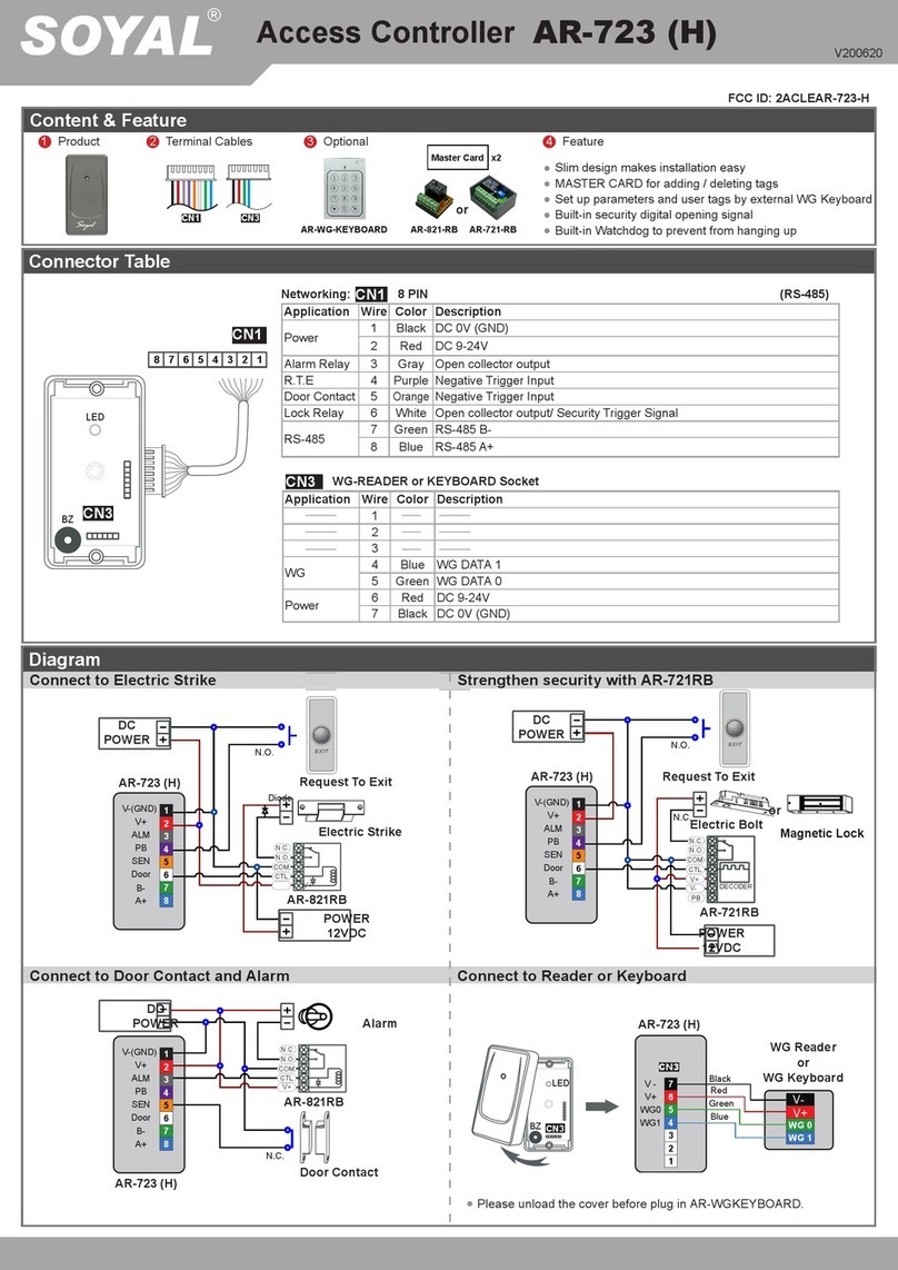
Strengthen security with AR-721RB
Electric Bolt Electric Bolt
Connect to Reader
Access programming mode → Add/Delete → Add -> RF-Learn → Input 5/6-digit user address
→ Input Tag Units(pcs) → Close Tag into RF Area
※ If adding a batch of Sequential tags, please input Tag Units(pcs) in the quantity of the tags and present the
tag with the lowest card code to the access controller.
1 2
Adding Tag by RF Learn Function Tag Information
SITE CODE
CARD CODE
SITE CODE
CARD CODE
Adding and Deleting Tag
※ User capacity: 16384 (00000~16383)
Access programming mode → Add/Delete → Add -> Card ID → Input 5/6-digit user address → Input Site Code → Input Card Code
11
Adding Tag by Tag ID
Access programming mode → Add/Delete → Delete -> Addr → Input Starting address → Input Ending address
1 5
Deleting User Address
Access programming mode → User Setting → Access Mode → Input User Address → 0: Invalid; 1: Card ; 2: Card or PIN; 3: Card & PIN
2 2
Setting up the access mode
Access programming mode → Add/Delete → Delete -> ID # → Input Site Code → Input Card Code
1 6
Deleting Tag by Tag ID
D. PIN Code
C. Initial setup
Access programming mode → User Setting → Password → Input
5/6-digit user address → Input 4-digit PIN (0001~9999) → Succeeded Or via
701Client set it on Users screen
21
Node ID of Reader Setting
Access programming mode → Parameters[1] → Node
ID → Input New Node ID : 1~254 (default value:001) → Main
Door Number : 0~255 → WG1 Door Number : 0~255 →
Show WG Message (0=No,1=Enable) → Network setting
→ Succeeded
3 1
Language Setting
Access programming mode → Tools → Language →
0EN → Succeeded → Initial system...
5 1
F. Enable Voice Module (supporting version : F/w Ver 3.02
or later)
Software Setting
701 Server
or
Programming
B. Entering and Exiting Programming Mode
Changing the Master Code
Access programming mode → Tools → Master Code →
Input the 6-digit new master code → Succeeded
5 2
A. Keyboard Lock/ Unlock
Lock/ Unlock
Press and , and at the same time to lock keyboard.
Press again to unlock.
Entering
Input 123456 or PPPPPP
[e.g.] The Default Value= 123456. If already changed the Master
Code= 876112, input 876112 → Access programming mode
P.S.If entering no instruction within 30 sec., it will automatically
leave the programming mode.
Exiting
Press the repeatedly → Quit or Quit and Arming
(Please refer to alarm / arming setting)
6 7
E. Setting up the alarm / arming
Conditions: 1. Arming enabled 2.Alarm system connected
Application:
1. Door open too long: Door is open longer than door relay time plus door close
time.
2. Force open (Opened without a valid user card): Access by force or illegal
procedure.
3. Door position abnormal: When power is o and then on, reader on arming
before power o.
Step 1. Click "Read."
Step 2. Select "Card
Reader" in RS485-2
section.
Step 3. Click "Write" to
nish the setting.
Hardware setting
Access programming mode → Tools → Ext. Comm Port → Voice
552
※ The Wiring of Disable "Share Door Relay" ( Set up via the parameters
setting Window of 701ServerSQL
※ The Wiring of Enable "Share Door Relay" ( Set up via the parameters
setting Window of 701ServerSQL)
