manuals.online logo
Brands
  1. Home
  2. •
  3. Brands
  4. •
  5. Teknik
  6. •
  7. Indoor Furnishing
  8. •
  9. Teknik Scribed Oak Storage Desk 5418294 User manual

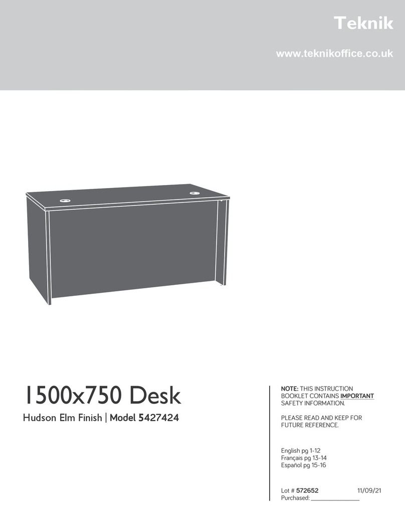
Teknik Scribed Oak Storage Desk 5418294 User manual

www.teknikoffice.co.uk
NOTE: THIS INSTRUCTION
BOOKLET CONTAINS IMPORTANT
SAFETY INFORMATION.
PLEASE READ AND KEEP FOR
FUTURE REFERENCE.
English pg 1-32
Français pg 33-36
Español pg 37-40
Scribed Oak Storage Desk
5418294
For all your
newfangled gadgetry.
Teknik
Table of Contents Assembly Tools Required
Part Identification
Hardware Identification
Assembly Steps
Safety
Hammer
Not actual size
No. 2 Phillips Screwdriver
Tip Shown Actual Size
2-3
4
5-32
33
Page 2
Now you know
our ABCs.
Part Identification
åWhile not all parts are labeled, some of the parts will have a label or an inked letter on the edge
to help distinguish similar parts from each other. Use this part identification to help identify similar parts.
A RIGHT END (1)
B OUTER LEFT END (1)
C INNER LEFT END (1)
D UPRIGHT (1)
E LEFT UPRIGHT (1)
F SMALL UPRIGHT (1)
G TOP (1)
H BOTTOM (1)
I MODESTY PANEL (1)
J UPPER SHELF (1)
K BACK (1)
L DOOR (1)
M ADJUSTABLE SHELF (1)
N BASE (1)
O SIDE SKIRT (4)
P DRAWER FRONT (1)
Q LARGE DRAWER FRONT (1)
R TOP MOLDING (1)
S PLINTH (1)
T LEFT FRONT END MOLDING (1)
U
RIGHT UPRIGHT END MOLDING (2)
V SHELF MOLDING (1)
W LEFT REAR END MOLDING (1)
D102 LARGE DRAWER SIDE (2)
D216 DRAWER SIDE (2)
D463 LARGE DRAWER BOX FRONT (2)
D464 DRAWER BOX FRONT (2)
D713 DRAWER BOTTOM (2)
Electric drill with 1/4" bit
(ONLY in indicated step)
Part Identification
Page 3
A
B
C
D
E
F
G
H
I
J
K
L
M
N
O
P
Q
R
S
T
U
V
W
O
O
O
U
D102
D102
D216
D216
D463
D463
D464
D464
D713
D713
Hardware Identification
åScrews are shown actual size. You may receive extra hardware with your unit.
Page 4
FILE
GLIDE - 2
3B
YEXTENSION
SLIDE - 2
XEXTENSION
RAIL - 2
(EXTENSION SET SHOWN SEPARATED)
FILE
ROD - 2
8B
40CA CABINET
RIGHT - 1 40CB CABINET
LEFT - 1 40CC DRAWER
RIGHT - 1 40CD DRAWER
LEFT - 1
BLACK 1-1/8" MACHINE SCREW - 1
21S
METAL
BRACKET - 3
4G
GOLD 1" MACHINE SCREW - 2
50S
BLACK 9/16" LARGE HEAD SCREW - 6
1S
BLACK 7/8" LARGE HEAD SCREW - 6
17S
BLACK 1-7/8" FLAT HEAD SCREW - 6
2S
36P CAM COVER - 6
12S BROWN 1" FLAT HEAD SCREW - 13
3S GOLD 5/16" FLAT HEAD SCREW - 16
METAL
PIN - 8
1R
BLACK 1/2" FLAT HEAD SCREW - 4
11S
DOOR
STOP - 1
4I
40H HINGE - 2
NAIL - 38
1N
30S BLACK 1-9/16" FLAT HEAD SCREW - 16
HIDDEN
CAM - 18
1F CAM
DOWEL - 18
2F
SILVER 1-1/2" MACHINE SCREW - 2
95S
KNOB - 1
69K RUBBER
SLEEVE - 4
2R
PULL - 2
70K
Step 1
å Assemble your unit on a carpeted floor or on the empty
carton to avoid scratching your unit or the floor.
å Push eighteen HIDDEN CAMS (1F) into the ENDS (A, B,
and C), UPRIGHTS (D and E), BOTTOM (H), and UPPER
SHELF (J). Then, insert the metal end of a CAM
DOWEL (2F) into each HIDDEN CAM.
Page 5
Arrow
1F
2F
(18 used)
Arrow
1F
2F
Do not tighten the HIDDEN CAMS in this step.
Insert the metal end of the CAM
DOWEL into the HIDDEN CAM.
Arrow
A
B
C
D
H
J
E
STOP
If you
purchased the
5418295 Hutch,
assemble that
unit first.
Step 2
Page 6
å Separate the EXTENSION SLIDES (Y) from the
EXTENSION RAILS (X) as shown in the enlarged diagram
below. Be prepared, the parts are greasy.
å Fasten the EXTENSION RAILS (X) to the RIGHT END (A)
and UPRIGHT (D). Use four GOLD 5/16” FLAT HEAD
SCREWS (3S).
å NOTE: For each EXTENSION RAIL, turn a SCREW into the
hole shown in the enlarged diagram. Then, slide the inner
cartridge of the EXTENSION RAIL in to find the other hole
that lines up with the hole in the END. Turn a SCREW into
this hole.
Open end
GOLD 5/16" FLAT HEAD SCREW
(4 used in this step)
3S
Push the black lever in and pull the SLIDE from the RAIL.
A
D
Surface with
HIDDEN CAMS
Surface with
HIDDEN CAMS
Y X
Open end
Remember:
Righty tighty.
Lefty loosey.
Finished edge
Notched edge
X
X
Step 3
Page 7
A
D
Surface with
HIDDEN CAMS
Surface with
HIDDEN CAMS
å Fasten the CABINET RIGHT (40CA) to the RIGHT END (A)
and CABINET LEFT (40CB) to the UPRIGHT (D). Use four
GOLD 5/16" FLAT HEAD SCREWS (3S) through holes #1
and #3.
GOLD 5/16" FLAT HEAD SCREW
(4 used in this step)
3S
1
2
3
4
1
2
3
4
Roller end
Roller end
Finished edge
Notched edge
å Fasten the SIDE SKIRTS (O) to the RIGHT END (A), LEFT
ENDS (B and C), and LEFT UPRIGHT (E). Use eight
BROWN 1" FLAT HEAD SCREWS (12S).
Step 4
Page 8
A
B
E
C
O
O
O
O
Surface with
HIDDEN CAMS
Surface with
HIDDEN CAMS
Surface without
HIDDEN CAMS
Surface without
HIDDEN CAMS
Unfinished edge
Unfinished edge
BROWN 1" FLAT HEAD SCREW
(8 used in this step)
12S
å Fasten the INNER LEFT END (C) to the MODESTY PANEL (I).
Use two BLACK 1-7/8" FLAT HEAD SCREWS (2S).
Step 5
Page 9
C
Surface with
HIDDEN CAMS
I
Notch
O
BLACK 1-7/8" FLAT HEAD SCREW
(2 used in this step)
2S
Do not stand the unit upright without the
BACK fastened. The unit may collapse.
Caution
å IMPORTANT: If you purchased the 418295 Hutch, you will
need to finish drilling through the three partially drilled holes in
the TOP (G) using your drill and 1/4" drill bit.
å Fasten the TOP MOLDING (R) to the TOP (G). Use five
BROWN 1" FLAT HEAD SCREWS (12S).
å To fasten the TOP (G) to the 418295 Hutch, use three BLACK
1-7/8" FLAT HEAD SCREWS (2S) through the TOP and into
the Hutch Ends and Upright.
å NOTE: The SCREWS to fasten the TOP to the 419295 Hutch
will come from the Hutch assembly.
Step 6
Page 10
If you purchased the 418295 Hutch,
finish drilling through these three holes.
R
G
Flat edge
BROWN 1" FLAT HEAD SCREW
(5 used for the TOP MOLDING)
12S
G
BLACK 1-7/8" FLAT HEAD SCREW
(3 used from the Hutch assembly)
2S
418295
Hutch End
418295
Hutch End
418295
Upright
å Fasten the OUTER LEFT END (B) to the TOP (G). Tighten
two HIDDEN CAMS.
Step 7
Page 11
Start Tighten
Arrow
Minimum
190 degrees
Caution
Risk of damage or
injury. HIDDEN CAMS
must be completely
tightened. HIDDEN
CAMS that are not
completely tightened
may loosen, and parts
may separate. To
completely tighten:
Arrow
Maximum
210 degrees
G
B
Surface with HIDDEN CAMS
R
å Fasten the INNER LEFT END (C) assembly to the TOP (G).
Tighten two HIDDEN CAMS.
Step 8
Page 12
Arrow
Minimum
190 degrees
Maximum
210 degrees
G
C
I
Surface with HIDDEN CAMS
For support, place packing
foam and magazines here.
å Fasten the LEFT UPRIGHT (E) to the TOP (G). Tighten two
HIDDEN CAMS.
å Fasten the LEFT UPRIGHT (E) to the MODESTY PANEL (I).
Use two BLACK 1-7/8" FLAT HEAD SCREWS (2S).
Step 9
Page 13
Arrow
Minimum
190 degrees
Maximum
210 degrees
G
I
E
Notched edge
Surface without
HIDDEN CAMS
BLACK 1-7/8" FLAT HEAD SCREW
(2 used in this step)
2S
Step 10
Page 14
å NOTE: Separate the LEFT END MOLDINGS (T and W). The
LEFT FRONT END MOLDING (T) is shorter than the LEFT
REAR END MOLDING (W). Do not confuse these MOLDINGS.
å Slide the LEFT FRONT END MOLDING (T) onto the notched
edges of the LEFT ENDS (B and C).
å *U.S. Patent No. 5,499,886
C
T
Notched edges
B
Slide the LEFT
FRONT END
MOLDING (T) onto
the notched edges.
Step 11
Page 15
å Slide the PLINTH (S) onto the notched edges of the LEFT
ENDS (B and C).
å Push a DOOR STOP (4I) into the hole in the LEFT
UPRIGHT (E).
å *U.S. Patent No. 5,499,886
C
S
E
4I
B
Finished edge
Slide the PLINTH (S)
onto the notched edges.
Step 12
Page 16
å Insert four METAL PINS (1R) into the SMALL UPRIGHT (F).
å Insert the METAL PINS (1R) in one end of the SMALL UPRIGHT (F) into the holes in the TOP (G).
å Fasten the UPPER SHELF (J) to the LEFT UPRIGHT (E). Tighten two HIDDEN CAMS.
å NOTE: Be sure the METAL PINS in the SMALL UPRIGHT insert into the holes in the UPPER SHELF.
G
(4 used)
Arrow
Minimum
190 degrees
Maximum
210 degrees
EJ
F
Finished edge
Notched edge
1R
Surface with
HIDDEN CAMS
å Slide the RIGHT UPRIGHT END MOLDING (U) onto the
notched edge of the LEFT UPRIGHT (E).
å *U.S. Patent No. 5,499,886
Step 13
Page 17
UE
Slide the RIGHT UPRIGHT END
MOLDING (U) onto the notched edge.
å Fasten the UPRIGHT (D) to the UPPER SHELF (J). Tighten
two HIDDEN CAMS.
Step 14
Page 18
Arrow
Minimum
190 degrees
Maximum
210 degrees
J
D
Don't worry. It isn't
Rome. This can be built
in a day.
Surface with
HIDDEN CAMS
Finished edge
Step 15
Page 19
å Slide the SHELF MOLDING (V) onto the notched edge of
the UPPER SHELF (J).
å *U.S. Patent No. 5,499,886
J
V
Notched edge
Slide the SHELF MOLDING (V) onto the notched edge.
å Fasten the BOTTOM (H) to the LEFT UPRIGHT (E).
Tighten two HIDDEN CAMS.
å Fasten the BOTTOM (H) to the UPRIGHT (D). Use two
BLACK 1-7/8" FLAT HEAD SCREWS (2S).
Step 16
Page 20
D
Arrow
Minimum
190 degrees
Maximum
210 degrees
H
E
This hole must be here.
Surface with
HIDDEN CAMS
BLACK 1-7/8" FLAT HEAD SCREW
(2 used in this step)
2S

Other Teknik Indoor Furnishing manuals
Teknik Shaker Style 5428225 User manual

Teknik

Teknik Shaker Style 5428225 User manual

Teknik 5427430 User manual

Teknik

Teknik 5427430 User manual

Teknik Canal Heights 5419228 User manual

Teknik

Teknik Canal Heights 5419228 User manual

Teknik 5418793 User manual

Teknik

Teknik 5418793 User manual

Teknik Avon 5422051 User manual

Teknik

Teknik Avon 5422051 User manual

Teknik Hudson 5427871 User manual

Teknik

Teknik Hudson 5427871 User manual

Teknik Scribed Oak Desk 5414836 User manual

Teknik

Teknik Scribed Oak Desk 5414836 User manual

Teknik 5426484 User manual

Teknik

Teknik 5426484 User manual

Teknik Elstree 5426910 User manual

Teknik

Teknik Elstree 5426910 User manual

Teknik Streamline L-Shaped Desk 5414417 User manual

Teknik

Teknik Streamline L-Shaped Desk 5414417 User manual

Teknik Elstree 5426909 User manual

Teknik

Teknik Elstree 5426909 User manual

Teknik Boulevard Cafe Desk 5420701 User manual

Teknik

Teknik Boulevard Cafe Desk 5420701 User manual

Teknik 5412885 User manual

Teknik

Teknik 5412885 User manual

Teknik Barrister 5414720 User manual

Teknik

Teknik Barrister 5414720 User manual

Teknik 5426436 User manual

Teknik

Teknik 5426436 User manual

Teknik 5414142 User manual

Teknik

Teknik 5414142 User manual

Teknik 5427415 User manual

Teknik

Teknik 5427415 User manual

Teknik Contemporary Bureau 5416966 User manual

Teknik

Teknik Contemporary Bureau 5416966 User manual

Teknik 5426510 User manual

Teknik

Teknik 5426510 User manual

Teknik Metro 5426461 User manual

Teknik

Teknik Metro 5426461 User manual

Teknik 5426135 User manual

Teknik

Teknik 5426135 User manual

Teknik 5427428 User manual

Teknik

Teknik 5427428 User manual

Teknik Hudson Chunky Desk 5425833 User manual

Teknik

Teknik Hudson Chunky Desk 5425833 User manual

Teknik Boulevard Cafe 5421950 User manual

Teknik

Teknik Boulevard Cafe 5421950 User manual

Popular Indoor Furnishing manuals by other brands

Balt Presentation Cart Assembly instructions

Balt

Balt Presentation Cart Assembly instructions

Armour Home Electronics 2110 manual

Armour Home Electronics

Armour Home Electronics 2110 manual

Habitat Genna 803457 Assembly instructions

Habitat

Habitat Genna 803457 Assembly instructions

Axley 006821 operating instructions

Axley

Axley 006821 operating instructions

juwel SB 80 Assembly instructions

juwel

juwel SB 80 Assembly instructions

Edsbyn Piece V-form Assembly instruction

Edsbyn

Edsbyn Piece V-form Assembly instruction

John Lewis BAMBOO GARMENT RAIL 57088001 user guide

John Lewis

John Lewis BAMBOO GARMENT RAIL 57088001 user guide

modway EEI-6167-WAL Assembly instructions

modway

modway EEI-6167-WAL Assembly instructions

Otto Verner 28451936 Assembly instructions

Otto

Otto Verner 28451936 Assembly instructions

Alice's Home BOHEME IBOBEDSIDE Assembly instructions

Alice's Home

Alice's Home BOHEME IBOBEDSIDE Assembly instructions

Rauch M0003 Assembly instructions

Rauch

Rauch M0003 Assembly instructions

zieta Crystals Series Assembly instructions

zieta

zieta Crystals Series Assembly instructions

GETINGE GROUP ARJOHUNTLEIGH Bari-Breeze Instructions for use

GETINGE GROUP

GETINGE GROUP ARJOHUNTLEIGH Bari-Breeze Instructions for use

Amart Furniture DANA 66952 Assembly instruction

Amart Furniture

Amart Furniture DANA 66952 Assembly instruction

NOA & NANI Karlstad 8 Drawer Chest Assembly instructions

NOA & NANI

NOA & NANI Karlstad 8 Drawer Chest Assembly instructions

Monarch Specialties I 7115 Assembly instructions

Monarch Specialties

Monarch Specialties I 7115 Assembly instructions

Spectrum Industries 68000 Series Assembly instructions

Spectrum Industries

Spectrum Industries 68000 Series Assembly instructions

Deltaco Gaming DC220 user manual

Deltaco Gaming

Deltaco Gaming DC220 user manual

manuals.online logo
manuals.online logoBrands
  • About & Mission
  • Contact us
  • Privacy Policy
  • Terms and Conditions

Copyright 2025 Manuals.Online. All Rights Reserved.