manuals.online logo
Brands
  1. Home
  2. •
  3. Brands
  4. •
  5. Teknik
  6. •
  7. Indoor Furnishing
  8. •
  9. Teknik Hythe 5426437 User manual

Teknik Hythe 5426437 User manual

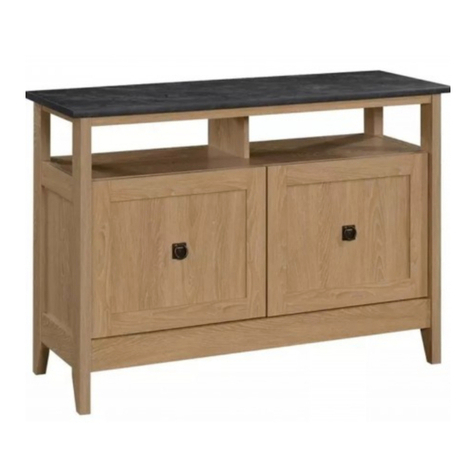
Hythe Wall Mounted TV Stand/Credenza
Model 5426437
Your holder for all
things awesome.
Teknik
www.teknikoffice.co.uk
Part Identification
Hardware Identification
Assembly Steps
No. 2 Phillips Screwdriver
Tip Shown Actual Size
WARNING
!
Table of Contents Assembly Tools Required
3
4
5-20
70 lbs.
70 lbs.
15-3/4"
15-3/4"
59-7/8"
59-7/8"
Use of a TV that is too heavy or large is hazardous. A TV that is too heavy will create a risk of a tip-over that can cause severe injury or
death. A TV that is too large for the available space might be accidentally pushed or bumped o the furniture, or subject to tip-over.
• Check the size and weight of your TV. Compare it to the diagram below – before you begin assembly!
•
This Sauder unit is designed for use with flat panel televisions weighing less than 70 pounds. Never use with a TV that weighs more
.
• The size of the television, front-to-back and side-to-side, must fit within the space defined in the diagram.
• Never place the front edge of the TV past the front edge of the TV support shelf (or stop molding – if equipped)
• Never allow the sides of the TV to extend past the side edges of the TV support surface.
• Be sure to apply the warning label as instructed later in the assembly. The label provides important safety related information.
Page 2
Electric drill with 5/16" bit
(ONLY in indicated step)
Hammer
Not actual size
Part Identification
åWhile not all parts are labeled, some of the parts will have a label or an inked letter on the edge
to help distinguish similar parts from each other. Use this part identification to help identify similar parts.
Now you know
our ABCs.
A TOP (1)
B LARGE SHELF (1)
C LEFT END (1)
D RIGHT END (1)
E LEFT UPRIGHT (1)
F RIGHT UPRIGHT (1)
G SMALL SHELF (1)
H SMALL UPRIGHT (1)
J BACK (1)
K BOTTOM (1)
L FRAME (2)
M FOOT (2)
N DOOR (2)
Page 3
A
B
C
D
E
F
G
H
J
K
L
M
N
L
M
N
Hardware Identification
åScrews are shown actual size. You may receive extra hardware with your unit.
Page 4
HIDDEN CAM - 16
1
L-WRENCH - 1
7
CAM SCREW - 16
2
1-9/16" PAN HEAD SCREW - 10
13
1/2" FLAT HEAD SCREW - 24
15
(Refer to the last step for proper
location and application)
WARNING LABEL - 1
8
522,68 22,68
70 lbs. 31,75 kg 31,75 kg
1/2" HEX HEAD SCREW - 4
16
WOOD DOWEL - 16
3
6BUMPER CARD - 1
1-3/16" HEX HEAD SCREW - 4
14
3/8" MACHINE SCREW - 4
17
2" PAN HEAD SCREW - 2
11 1-7/8" HEX HEAD SCREW - 8
12
9PULL - 2 WALL ANCHOR - 2
10
APPLIQUE CARD - 1
4
HINGE - 4
5
Hardware Usage Guide
HOW TO USE A HIDDEN CAM & CAM SCREW OR CAM DOWEL
NOTE: Various CAM SCREWS or a CAM DOWEL may be used.
Cam Screws Cam Dowel
Turn the CAM SCREW or
gently tap the CAM DOWEL
until the shoulder is against
the surface of the part.
1.
Hidden CamHidden Cam
Arrow
Push a HIDDEN CAM into
the part. The arrow in the
HIDDEN CAM must point
toward the hole in the
edge of the board.
Hole
2.
3.
1
2
Insert the CAM SCREW or CAM DOWEL into the
HIDDEN CAM. Tighten the HIDDEN CAM.
Page 5
Step 1
å Assemble your unit on a carpeted floor or on the empty
carton to avoid scratching your unit or the floor.
å Push six HIDDEN CAMS (1) into the LARGE SHELF (B)
and ENDS (C and D).
å Turn eight CAM SCREWS (2) into the LARGE SHELF (B)
and ENDS (C and D).
Page 6
2
B
C
D
Arrow
1
å Insert two WOOD DOWELS (3) into the ENDS (C and D).
å Fasten the ENDS (C and D) to the LARGE SHELF (B).
Tighten four HIDDEN CAMS.
å NOTE: Be sure the WOOD DOWELS in the ENDS insert
into the LARGE SHELF.
Step 2
Page 7
B
C
D
33
Groove
å Push two HIDDEN CAMS (1) into the SMALL UPRIGHT (H).
å Insert one WOOD DOWEL (3) into the SMALL UPRIGHT (H).
å Fasten the SMALL UPRIGHT (H) to the LARGE SHELF (B).
Use two 1-9/16" PAN HEAD SCREWS (13).
å NOTE: You should start each SCREW a few turns before
completely tightening any of them.
å NOTE: Be sure the WOOD DOWEL in the SMALL UPRIGHT
inserts into the LARGE SHELF.
Step 3
Page 8
B
H
H
Arrow
1
3
Suface and edge
with HIDDEN CAMS
1-9/16" PAN HEAD SCREW
(2 used in this step)
13
å Turn six CAM SCREWS (2) into the TOP (A).
å Insert three WOOD DOWELS (3) into the TOP (A).
å Fasten the TOP (A) to the ENDS (C and D) and SMALL
UPRIGHT (H). Tighten six HIDDEN CAMS.
å NOTE: Be sure the WOOD DOWELS in the TOP insert
into the ENDS and SMALL UPRIGHT.
Step 4
Page 9
H
A
A
2
3
C
D
3
3
The edge holes are
closer to this edge.
å Push six HIDDEN CAMS (1) into the UPRIGHTS (E and F)
and SMALL SHELF (G).
å Carefully turn the UPRIGHTS (E and F) over.
å Turn two CAM SCREWS (2) into the other surfaces of
the UPRIGHTS (E and F).
Step 5
Page 10
Arrow
1
2
1
Arrow
G
F
E
F
E
F
L
I
P
O
V
E
R
å Insert four WOOD DOWELS (3) into the UPRIGHTS (E and F).
å Fasten the UPRIGHTS (E and F) to the SMALL SHELF (G). Tighten two HIDDEN CAMS.
å NOTE: Be sure the WOOD DOWELS in the UPRIGHTS insert into the SMALL SHELF.
å Carefully turn the larger assembly onto the TOP (A).
å Insert two WOOD DOWELS (3) into the LARGE SHELF (B).
å Fasten the UPRIGHTS (E and F) to the LARGE SHELF (B). Tighten four HIDDEN CAMS.
å NOTE: Be sure the WOOD DOWELS in the LARGE SHELF insert into the UPRIGHTS.
Step 6
Page 11
3
A
B
Groove
G
F
E
G
F
E
3
Surface with
HIDDEN CAMS
Surface with
HIDDEN CAMS
Surface with
HIDDEN CAMS
Finished edge
Finished edge
Surface with
HIDDEN CAMS
å Slide the BACK (J) into the grooves in the LARGE SHELF (B) and ENDS (C and D).
å Insert four WOOD DOWELS (3) into the ENDS (C and D) and UPRIGHTS (E and F).
å Fasten the BOTTOM (K) to the ENDS (C and D) and UPRIGHTS (E and F). Use eight 1-9/16"
PAN HEAD SCREWS (13).
å NOTE: You should start each SCREW a few turns before completely tightening any of them.
å NOTE: Be sure the WOOD DOWELS in the ENDS and UPRIGHTS insert into the BOTTOM.
å NOTE: Be sure the BACK (J) inserts into the groove in the BOTTOM.
Step 7
Page 12
Unfinished surface
B
C
D
J
3
C
D
J
F
K
E
(4 used)
1-9/16" PAN HEAD SCREW
(8 used in this step)
13
Groove
Step 8
Page 13
å Fasten the FEET (M) to the BOTTOM (K). Tighten four
1/2" HEX HEAD SCREWS (16) using the L-WRENCH (7).
K
7
M
M
1/2" HEX HEAD SCREW
(4 used in this step)
16
å Carefully turn your unit onto its front edges.
å NOTE: You should start each SCREW a few turns before
completely tightening any of them.
å Fasten one of the FRAMES (L) to the LEFT END (C). Tighten
two 1-3/16" HEX HEAD SCREWS (14) using the L-WRENCH (7).
å Fasten the FRAME (L) to the TOP (A) and BOTTOM (K). Tighten
four 1-7/8" HEX HEAD SCREWS (12) using the L-WRENCH (7).
Step 9
Page 14
K
C
A
7
The leg must be here.
12
1-3/16" HEX HEAD SCREW
(2 used for the END)
14
1-7/8" HEX HEAD SCREW
(4 used for the TOP and BOTTOM)
12
L
Step 10
Page 15
å NOTE: You should start each SCREW a few turns before
completely tightening any of them.
å Fasten the remaining FRAME (L) to the RIGHT END (D). Tighten
two 1-3/16" HEX HEAD SCREWS (14) using the L-WRENCH (7).
å Fasten the FRAME (L) to the TOP (A) and BOTTOM (K). Tighten
four 1-7/8" HEX HEAD SCREWS (12) using the L-WRENCH (7).
K
D
A
7
The leg must be here.
12
1-3/16" HEX HEAD SCREW
(2 used for the END)
14
1-7/8" HEX HEAD SCREW
(4 used for the TOP and BOTTOM)
12
L
Step 11
Page 16
å 1st-Carefully stand your unit upright against the wall in its final location. Strike a mark through the center of each hole
in the brackets in the FRAMES (L). Move your unit away from the marks.
å 2nd-Drill a 5/16" hole on each mark.
å 3rd-While you squeeze the wings together, gently tap two WALL ANCHORS (10) into the holes until they are even with
the surface of the wall.
å Place the brackets in the FRAMES (L) over the WALL ANCHORS (10).
å Turn two 2" PAN HEAD SCREWS (11) through the holes in the FRAMES (L) and into the WALL ANCHORS (10).
å NOTE: You will need to turn the SCREWS (11) multiple turns to completely tighten and secure your unit to the wall.
L
L
10
2" PAN HEAD SCREW
(2 used in this step)
11
1st
2nd
3rd
Mark and drill a 5/16"
hole into the wall.
Mark and drill a 5/16"
hole into the wall.
Step 12
Page 17
å Fasten one PULL (9) to one of the DOORS (N) exactly as
shown. Use two 3/8" MACHINE SCREWS (17).
å Fasten two HINGES (5) to the DOOR (N). Use four 1/2"
FLAT HEAD SCREWS (15).
å Repeat this step for the other DOOR.
5
1/2" FLAT HEAD SCREW
(8 used for the HINGES)
15
N
N
F
L
I
P
O
V
E
R
3/8" MACHINE SCREW
(4 used for the PULLS)
17
The narrow side of the
PULL is closer to this edge.
9
Step 13
Page 18
å Before fastening the DOOR to your unit, be sure the mounting
screw is against the stops as shown in the right diagram. If it
isn't, loosen the mounting screw to slide it against the stops.
Then tighten the mounting screw.
å Fasten the DOORS (N) to the ENDS (C and D) as shown in the
lower diagram. Use sixteen 1/2" FLAT HEAD SCREWS (15).
You should start each SCREW a few turns before completely
tightening any of them.
å Peel the BUMPERS from the BUMPER CARD (6) and stick
them onto the DOORS (N) where they will come into contact
with the UPRIGHTS (E and F).
å See the next step for DOOR adjustments.
C
D
N
N
6
F
E
1/2" FLAT HEAD SCREW
(16 used for the HINGES)
15
6
Mounting
screw
Stop
Hinge
Step 14
Page 19
å Refer to the enlarged diagram to identify the parts on
the HINGES.
å The DOORS may need some adjustments. Follow the text
below to make needed adjustments.
å DOOR ADJUSTMENTS:
To adjust the DOORS from side to side (horizontal), turn the
adjusting screw in or out.
å To adjust the DOORS in or out (depth), loosen the mounting
screw one turn and move the DOORS in or out, as needed.
Tighten the mounting screw after making adjustments.
Adjusting screw (horizontal)
Mounting screw (depth)
Step 15
Page 20
50 lbs. total
å Peel APPLIQUES from the APPLIQUE CARDS (4) and stick them onto each visible HIDDEN CAM.
å Apply the WARNING LABEL (8) to the TOP (A). You should be able to read the label when the TV is removed from the
unit. Peel o the backing and apply the label as shown.
å NOTE: This is a permanent label intended to last for the life of the product. Once applied, do not try to remove it.
å NOTE: Please read the back pages of the instruction booklet for important safety information.
å This completes assembly. Clean with a damp cloth. Wipe dry.
5
70 lbs.
522,6822,68
70 lbs. 31,75 kg 31,75 kg
70 lbs.
25 lbs.
A
8
4
50 lbs. total
To cover HIDDEN CAMS

Other Teknik Indoor Furnishing manuals

Teknik Executive Trestle Desk 5424128 User manual

Teknik

Teknik Executive Trestle Desk 5424128 User manual

Teknik 5414873 User manual

Teknik

Teknik 5414873 User manual

Teknik Hythe 5426438 User manual

Teknik

Teknik Hythe 5426438 User manual

Teknik Spanish Style Desk 5420114 User manual

Teknik

Teknik Spanish Style Desk 5420114 User manual

Teknik Essentials L-Shaped Desk 5425092 User manual

Teknik

Teknik Essentials L-Shaped Desk 5425092 User manual

Teknik 5418793 User manual

Teknik

Teknik 5418793 User manual

Teknik Boutique Style Desk User manual

Teknik

Teknik Boutique Style Desk User manual

Teknik 5418269 User manual

Teknik

Teknik 5418269 User manual

Teknik Wide Bookcase 5420282 User manual

Teknik

Teknik Wide Bookcase 5420282 User manual

Teknik Trestle 5410421 User manual

Teknik

Teknik Trestle 5410421 User manual

Teknik 5401562 User manual

Teknik

Teknik 5401562 User manual

Teknik Lateral Filer 5421114 User manual

Teknik

Teknik Lateral Filer 5421114 User manual

Teknik Clifton Place 5421113 User manual

Teknik

Teknik Clifton Place 5421113 User manual

Teknik Hampstead Park 5420731 User manual

Teknik

Teknik Hampstead Park 5420731 User manual

Teknik Home Study 5426616 User manual

Teknik

Teknik Home Study 5426616 User manual

Teknik Barrister Home User manual

Teknik

Teknik Barrister Home User manual

Teknik 5424943 User manual

Teknik

Teknik 5424943 User manual

Teknik 5427430 User manual

Teknik

Teknik 5427430 User manual

Teknik Elstree 5426909 User manual

Teknik

Teknik Elstree 5426909 User manual

Teknik Shaker Style 5428225 User manual

Teknik

Teknik Shaker Style 5428225 User manual

Teknik Barrister Home 5417772 User manual

Teknik

Teknik Barrister Home 5417772 User manual

Teknik Streamline L-Shaped Desk 5414417 User manual

Teknik

Teknik Streamline L-Shaped Desk 5414417 User manual

Teknik Hampstead Park 5423704 User manual

Teknik

Teknik Hampstead Park 5423704 User manual

Teknik Hudson 5425825 User manual

Teknik

Teknik Hudson 5425825 User manual

Popular Indoor Furnishing manuals by other brands

IKEA JONISK AA-96165-2 Assembly instructions

IKEA

IKEA JONISK AA-96165-2 Assembly instructions

BDI CIRRUS 8158 Assembly instructions

BDI

BDI CIRRUS 8158 Assembly instructions

Forte GLRK03 Assembling Instruction

Forte

Forte GLRK03 Assembling Instruction

Kimex 047-0003 installation manual

Kimex

Kimex 047-0003 installation manual

VISIONARY DESIGNS MOD-1468 quick start guide

VISIONARY DESIGNS

VISIONARY DESIGNS MOD-1468 quick start guide

Next BRONX 685006 Assembly instructions

Next

Next BRONX 685006 Assembly instructions

DITALIA MP-80 Assembly manual

DITALIA

DITALIA MP-80 Assembly manual

Dimensions Furniture MoDRN Retro Glam Marion Assembly instructions

Dimensions Furniture

Dimensions Furniture MoDRN Retro Glam Marion Assembly instructions

Performance Tool W85020 owner's manual

Performance Tool

Performance Tool W85020 owner's manual

Safavieh Furniture Caraway FOX8202A quick start guide

Safavieh Furniture

Safavieh Furniture Caraway FOX8202A quick start guide

BYYU GAMER 91661 manual

BYYU

BYYU GAMER 91661 manual

Southern Enterprises MS333400TX Assembly instructions

Southern Enterprises

Southern Enterprises MS333400TX Assembly instructions

for Living Kitchen Cart 068-1303-4 Assembly instructions

for Living

for Living Kitchen Cart 068-1303-4 Assembly instructions

VAS XL50-2MC Assembly instructions

VAS

VAS XL50-2MC Assembly instructions

Ticaa Maria 310 H1000011866 Instructions for use

Ticaa

Ticaa Maria 310 H1000011866 Instructions for use

Royo GO ON 90 manual

Royo

Royo GO ON 90 manual

Pronto wonen 0683/01-2Gl-A K Assembly instructions

Pronto wonen

Pronto wonen 0683/01-2Gl-A K Assembly instructions

Northbeam ADC0583300010 manual

Northbeam

Northbeam ADC0583300010 manual

manuals.online logo
manuals.online logoBrands
  • About & Mission
  • Contact us
  • Privacy Policy
  • Terms and Conditions

Copyright 2025 Manuals.Online. All Rights Reserved.