Tenma 72-9400A User manual

TM
TM
Page <2> V1.007/12/23
Newark.com/exclusive-brands
Farnell.com/exclusive-brands
Element14.com/exclusive-brands
1. Overview
The Insulation Resistance Tester is designed with brand-new design and combination of massive integrated and digital circuits;
it can measure insulation resistance, AC voltage, etc. and enjoys high degree of accuracy, stable performance, easy operation
and reliability. It is used for insulation resistance measurement for insulation materials and various kinds of electric equipment
such as transformer, electric machines, cables, switches, electrical appliances, a ideal tool for electric equipment maintenance,
testing and inspection.
2. Safety Information
It is designed and manufactured in compliance with: IEC61010-1 CATlll 600V, Double Insulation and Pollution Degree 2
standards. Operate as specied in the manual, otherwise the protection oered by the tester would be impaired.
Compliance Standards: EN61010-1:2010; EN61010-2-030:2010; EN61557-1:2007; EN61557-2:2007; EN61326-1:2013;
EN61326-2-2:2013
Safety Symbols 1
Danger Identies conditions and actions that may pose hazard to the users.
Warning Alerts users to avoid electric shock.
Caution Identies conditions and actions that may cause damage to the instrument of aect accurate
measurement.
Danger
• Do not measure any AC circuit with voltages above 750V.
• Do not measure in ammable places. Spark may cause explosion.
• In case that the surface of the instrument is wet or the operator’s hands are wet, please do not operate this instrument.
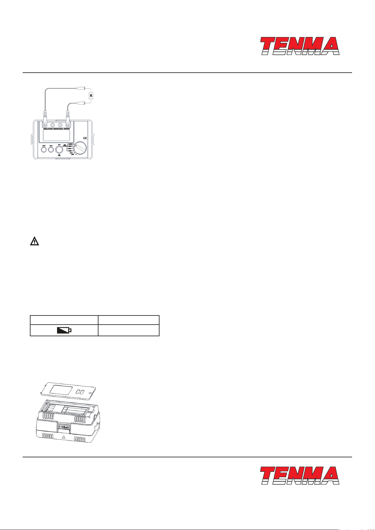
• Do not touch the electric conduction parts of test leads when testing.
• Do not open the battery cover when testing.
• When insulation resistance is measured, do not touch the electric wire under test.
Warning
• Stop using the instrument if it works abnormally. For example: the equipment is damaged or metal parts are exposed.
• Operator must be careful when voltage exceeds 33Vrms, 46.7Vacrms of 70V DC. Such kinds of voltage may cause
electric shock.
• Do not replace the battery in wet conditions.
• Ensure that all test wires are connected to the test ports of tester securely.
• When opening the battery cover, make sure that the instrument is turned o.
• Please read carefully and understand the manual before using the instrument.
• Use the instrument as specied in the manual at any time and store the manual for further reference.
• When the instrument is testing, misoperation may lead to an accident and damage of equipment.
Caution
• Before testing insulation resistance, the circuit under test must be completely discharged and completely isolated with
other power circuits.
• In case the test pen is damaged and needs to be replaced , use only the test leads with the same model or identical
electrical specications.
• When the battery indicator ( ) indicates that the power runs out, do not use the instrument. Remove the battery and store
the instrument if it is not in use for a long time.
• Do not store or use this instrument in heat, humid, ammable, explosive and strong electromagnetic eld environments.

TM
TM
Page <3> V1.007/12/23
Newark.com/exclusive-brands
Farnell.com/exclusive-brands
Element14.com/exclusive-brands
Safety Symbols 2
The instrument has double insulation or reinforced insulation.
ACV AC Voltage
Ground
Comply with European Union standards
3. Technical Specication
Accuracy ±(a% reading+digits); calibration per year.
Ambient Temperature (23±5)°C
Environmental Humidity 45% to 75%
Insulation Resistance Measurement
Rated Voltage 100V 250V 500V 1000V
Test Range 0.00MΩ to 5.5G (When it is about less than 4MΩ, buzzer outputs alarming
sounds). Notes: (100V) 0.00MΩ to 100MΩ
Opened Voltage DC100V ±10% DC250V ±10% DC500V ±10% DC1000V ±10%
Rated Test
Current
When load is
100kΩ, the rated
testing current is
0.9mA~1.1mA
When load is
250kΩ, the rated
testing current is
0.9mA~1.1mA
When load is
500kΩ, the rated
testing current is
0.9mA~1.1mA
When load is
1MΩ, the rated
testing current is
0.9mA~1.1mA
Shorted Current About less than 1.8mA
Accuracy 0.00MΩ to 99MΩ: ±(3% + 5 digits); 100MΩ to 5.5GΩ: ±(5% + 5 digits)
Voltage Measurement
AC Voltage
Test Range 30V~750V (50Hz/60Hz)
Resolution 1V
Accuracy ±(2% + 3 digits)
• Display: LCD, 1999 count
• Low Battery Indication: “ ”
• Overload Indication: “>5.5GΩ” for insulation resistance measurement; “OL V” for voltage measurement
• Autoranging
• Discharge voltage automatically
• Backlight, suitable in dark site
• Red warning light (warning light is on when high voltage outputs)
• Working conditions: 0°C to +35°C; relative humidity is 75% or less; altitude: 2000m
• Storage conditions: -20°C to +60°C / relative humidity is 80% or less
• Dimensions: 150mm (L) × 100mm (W) × 71mm (D)
• Power supply: alkaline batteries, 1.5V (5#) × 6
• Weight: 0.5kg (with battery)
• Accessories: test leads, instruction manual, carrying case, galas

TM
TM
Page <4> V1.007/12/23
Newark.com/exclusive-brands
Farnell.com/exclusive-brands
Element14.com/exclusive-brands
4. Tester’s Structure
1. EARTH: Insulation resistance input jack
2. G: Negative voltage input jack
3. V: Positive voltage input jack
4. LINE: Insulation resistance input jack ( high voltage output)
5. LCD screen
6. Backlight Button
7. Data-hold Button
8. Insulation resistance test button
9. Functional Knob
5. Functions of Keys and Knobs
1. HOLD: data hold;
2. LIGHT: tum on or of the backlight source;
3. TEST: tum on or o high voltage test;
4. Test AC voltage when function knob points to ACV:
5. Test DC voltage when function knob points to DCV;
6. Test insulation resistance when the function knob points to 100V/250V/500V/1000V
(select the desired output voltage).
6. Voltage Measurement
To measure AC voltage, do the following:
(1) Insert the red test lead into the • V • input port and the black test lead into the “G” Input port.
(2) Place the function knob in the ICV function position to test AC voltage.
Caution
• Do not input AC voltage over 750Vrms. It is possible to display a higher voltage but it may cause damage to the instrument
or electric shock.
• After all the testing operations, disconnect the test leads and the circuit under test, and remove the test leads from the
instrument input jack.
• In case the battery cover is opened, do not conduct any test.
7. Insulation Resistance Measurement
Caution
a. When measuring insulation resistance, please strictly place the two test probes separately. Do not mix them up.
b. Neither short circuit the two test probes under high voltage output state nor measure insulation resistance after high
voltage outputs.
c. In case the battery cover is opened, do not conduct any test.

TM
TM
Page <5> V1.007/12/23
Newark.com/exclusive-brands
Farnell.com/exclusive-brands
Element14.com/exclusive-brands
1. Turn the function knob to select one of test voltages 100V/250V/500V/1000V.
(1) Before testing insulation resistance, the circuit under test must be completely discharged and completely isolated from
power supply circuit.
(2) Insert the red test wire into the “ LINE” input port and the black test wire into the “EARTH” input port.
(3) Connect the red and black alligator clip to the circuit under test. The voltage is output from the LINE port.
2. Continuous Measurement
After function knob is set to one of test voltages 100V/250V/500V/1000V, press the TEST key, the instrument will be self-
locked to measure continuously. The test voltage will be output and TEST button will light up. With the measurement nished,
press TEST button to unlock and stop the measurement.
Caution
• Make sure the tested circuit is de-energized before measurement. Do not measure the insulation of any energized equip-
ment or wire.
• After the measurement is completed, do not touch the circuit by your hand. The capacitance stored in the circuit can cause
electric shock.
• Do not touch test wires when they are disconnected from tested circuit, wait until the test voltage is completely discharged.
• In case the battery cover is opened, do not conduct any test.
8. Battery Replacement
Low Voltage Symbol Battery Voltage
7V or less
Please follow these steps to replace batteries:
(1) In order to avoid the risk of electric shock, rstly turn o the power source before replacing the battery (i.e. the function
knob points at OFF) and remove the test wires.
(2) Unscrew the screws on the cover of battery compartment and remove the battery compartment. Replace six batteries.
(3) After the batteries are replaced, ensure to fasten the screws.

TM
TM
Page <6> V1.007/12/23
Newark.com/exclusive-brands
Farnell.com/exclusive-brands
Element14.com/exclusive-brands
Important Notice : This data sheet and its contents (the “Information”) belong to the members of the AVNET group of companies (the “Group”) or are licensed to it. No licence is granted for
the use of it other than for information purposes in connection with the products to which it relates. No licence of any intellectual property rights is granted. The Information is subject to change
without notice and replaces all data sheets previously supplied. The Information supplied is believed to be accurate but the Group assumes no responsibility for its accuracy or completeness,
any error in or omission from it or for any use made of it. Users of this data sheet should check for themselves the Information and the suitability of the products for their purpose and not make
any assumptions based on information included or omitted. Liability for loss or damage resulting from any reliance on the Information or use of it (including liability resulting from negligence or
where the Group was aware of the possibility of such loss or damage arising) is excluded. This will not operate to limit or restrict the Group’s liability for death or personal injury resulting from its
negligence. TENMA is the registered trademark of Premier Farnell Limited 2019.
Caution
• Please do not mix old and new batteries up.
• Please note battery’s polarity when installing batteries.
Danger
• In case the battery cover is opened, do not conduct any test.
9. Maintenance
Clean the casing:
1. Clean the surface by a piece of moist soft cloth or sponge with clean water.
2. To avoid any damage to the instrument, do not submerge it into water.
3. When the instrument is wet, please dry ~ before storing.
4. When there is need to calibrate or repair the instrument, please have it serviced by professional personnel or designated
service centre.
Table of contents
Other Tenma Test Equipment manuals

Tenma
Tenma 72-7985 User manual

Tenma
Tenma 72-2650 User manual

Tenma
Tenma 72-3565 User manual

Tenma
Tenma 72-9355 User manual

Tenma
Tenma 72-10175 User manual

Tenma
Tenma DSO Series User manual

Tenma
Tenma 72-2650 User manual

Tenma
Tenma 72-9405 User manual

Tenma
Tenma 72-6802 User manual

Tenma
Tenma 72-6947 User manual

Tenma
Tenma 72-490 User manual

Tenma
Tenma 72-7615 User manual

Tenma
Tenma 72-2665 User manual

Tenma
Tenma 72-14520 User manual

Tenma
Tenma 72-3575 User manual

Tenma
Tenma 72-17175 User manual

Tenma
Tenma 72-7630 User manual

Tenma
Tenma 72-9966 User manual

Tenma
Tenma 72-8710 User manual

Tenma
Tenma 72-6694 User manual