Tenma 72-14520 User manual

1
Digital Phosphor Storage Oscilloscope
Model No. 72-14520, 72-14525,
72-14530 & 72-14535

2
When using electrical appliances, basic safety precautions should always
be followed to reduce the risk of re, electric shock and injury to persons or
property.
Read all instructions before using the appliance and retain for future reference.
• This meter is designed to meet IEC61010-1, 61010-2-032, and 61010-2-033 in
Pollution Degree 2, Measurement Category (CAT II 150V when switched to 1X and
300V CAT II when switched to 10X) and double Insulation.
• Check that the voltage indicated on the rating plate corresponds with that of the
local network before connecting the product to the mains power supply.
• Do not operate this product with a damaged plug or cord, after a malfunction or
after being dropped or damaged in any way.
• Check the product before use for any damage. Should you notice any damage on
the cable or casing, do not use.
• This product contains no user-serviceable parts. All repairs should only be carried
out by a qualied engineer. Improper repairs may place the user at risk of harm.
• Take caution when voltages are above 60V DC and 30V ACrms.
• The earth probe must only be used to connect to ground, never connect to a
voltage source.
• This product must be earthed using the mains power cord ground connection.
• Do not disconnect from the mains supply and it’s ground connection when any item
is connected to this product for measurement.
• Children should be supervised to ensure that they do not play with the product.
• Always disconnect from the mains when the product is not in use or before
cleaning.
• Do not use the product for any purpose other than that for which it is designed.
• Do not operate or store in an environment of high humidity or where moisture may
enter the product as this can reduce insulation and lead to electric shock.
PRODUCT OVERVIEW
Main Features
• Two and four channels with HD colour 8” LCD display
• Real-time continuous hardware waveform recording and waveform analysis
• Multi‐waveform mathematical operation function
• Automatic measurement of 34 waveform parameters
• Edge, video, pulse width and advanced trigger functions
• Waveform capture rate of up to 50,000wfms/s
• Supports plug and play USB storage devices and communication with PC
• Unique waveform recording and replay function
WHAT’S INCLUDED
• Digital Oscilloscope Unit
• Mains power lead
• User Manual
• Communications software CD
• USB lead
• Selectable 1:1/10:1 passive probes
Optional accessories
• LAN port module

3
CONTROLS AND CONNECTIONS
OPERATING PARAMETERS
• The oscilloscope also has high performance index and powerful functions required
for faster measurements.
• Faster signals can be observed with the oscilloscope via 1GS/s real‐time sampling.
• Powerful trigger and analysis ability make it easier to capture and analyse
waveforms.
• Clear LCD and mathematical operating functions make it easy to use to observe
and analyse signal problems in a faster and clearer way.
1. Screen display area
2. Copy/print screen
3. Multifunctional control
4. Function menu
5. Automatic setting
6. Run/stop
7. Single trigger control
8. All clear
9. Calibration and ground terminal
10. Trigger control area
11. Horizontal control area
12. Analogue channel inputs
13. Vertical control area
14. Control menu
15. USB HOST Interface
16. Power on/off
REAR PANEL
1. External trigger input
2. Pass/Fail output
3. USB Socket
4. LAN network
5. Safety Lock
6. AC Power Socket
7. Main power switch
1 2 3 4
5
5
6
7
8
9
10111213141516
1 2 3 4 5 6 7

4
• Boot check
• Power on the unit at the rear followed by the soft power button on the front panel.
• The oscilloscope then run through a set on self test functions followed by the
display screen showing.
• Take the probe and connect its BNC header to the BNC terminal of the
oscilloscope. Connect the probe’s main alligator clip to the “Calibration terminal”
and the ground clip also connected to the “Ground terminal”.
OPERATION
AUTO SET WAVEFORM DISPLAY
Probe compensation
• Perform this adjustment when connecting the probes
to any input channel for the rst time or errors in the
measurement may result.
• Set the attenuation coefcient in the probe menu and the
switch on the probe to 10x
• Enable CH1 and press AUTO.
• Observe the shape of the displayed waveform.
• Adjust the variable capacitor on the probe with an insulated screwdriver until a
correct waveform is achieved.
• The oscilloscope features an AUTO SET function which automatically adjusts the
vertical deection factor, scanning time base and trigger mode based on the input
signal until the most appropriate waveform is displayed.
Using the AUTO SET function
• Connect the signal to be measured to the signal input channel.
• Press AUTO and the oscilloscope will adjust the vertical scale factor, timebase, and
trigger mode according to the input signals.
Calibration Terminal
Ground Terminal
Correct Compensation Under CompensationOver Compensation

5
DISPLAY SETTING CONTROLS
Vertical control panel
• 1 2 3 4: open or close the four channels display. Model dependent.
• MATH: Open the mathematical operations menu for add, subtract,
multiply, divide, FFT, ltering, logic, and advanced operations.
• REF: Recall previously stored reference waveforms, can compare
currently measured waveform with reference waveforms.
• VERTICAL POSITION CONTROL: Used to adjust the vertical
position of the current channel waveform. Press this knob to return
the channel display back to the midpoint position.
• VERTICAL SCALE CONTROL: Used to adjust the vertical scale of
the current waveform. The vertical scale has 1, 2, and 5 steps.
• Pressing the button allows the vertical adjustment to switch between coarse and
ne adjustment mode.
Level (horizontal) control panel
• Displays window extension, independent timing, and holdoff time.
• HORIZONTAL POSITION CONTROL: Adjusts the horizontal position
of the current channel waveform. Press this control to return the
channel display back to the midpoint position.
• HORIZONTAL SCALE CONTROL: Used to adjust the vertical scale of
the current waveform. The vertical scale has 1, 2, and 5 steps.
• Pressing the SCALE button allows the vertical adjustment to switch
between main and extensible window mode.
Trigger system
• TRIGGER LEVEL CONTROL: Adjusts the currently selected trigger level.
Press the control to return the trigger level back to the midpoint position.
• TRIG MENU: Press to display the trigger menu.
• FORCE: Press to generate a trigger event once.
• HELP: Displays built-in help system.
Auto Setting
• When this key is pressed, the oscilloscope will automatically
adjust the vertical scale factor, timebase, and trigger mode
according to the input signals.
Run/Stop
• Press the key to “run” or “stop” sampling. RUN state is indicated by green
light. STOP state is indicated by red light.
Single
• Set to single trigger mode. After the trigger point the oscilloscope
will stop sampling.
Clear
• Clear all waveforms. If the oscilloscope is in the “RUN” state, it will
continue to display new waveforms. The screen will momentarily clear if
in “stop” state when “run” is pressed and sampling re-starts.
Screen Copy
• Copy the screen to a BMP format image and store it to USB device.

6
Multi-purpose Control
• Press the DISPLAY button and press F3 or F4 to select the
brightness options, then use the control to adjust the brightness.
• Press the control to conrm the setting.
• During menu operations the control can be used to select various
sub menu options, then press it again to conrm selection.
Function Keys
• MEASURE: Measure setting menu: can set
measure source to all parameters, custom
parameters, perform measurement statistics,
select measurement indicators, etc.
• ACQUIRE: Sampling setting menu to set up
acquisition mode and storage.
• STORAGE: Storage interface can select different types of storage and waveform
settings, which can be stored internally or through USB device.
• CURSOR: Cursor measurement menu can measure waveform’s time and voltage
manually with cursor. Press F1 to turn on or off.
• DISPLAY: Select display settings, such as display type, format, duration, grid
brightness, and waveform brightness.
• UTILITY: The utility menu can choose between some less commonly used settings
such as self-calibration, system information, language, menu display, waveform
recording, pass test, square wave output, frequency meter, system upgrades, back-
light brightness, output, etc. using relevant function button.
• DEFAULT: Restore to factory default settings.
USER INTERFACE
1
12
2 3 4 5 6
7 8 9 10
11

7
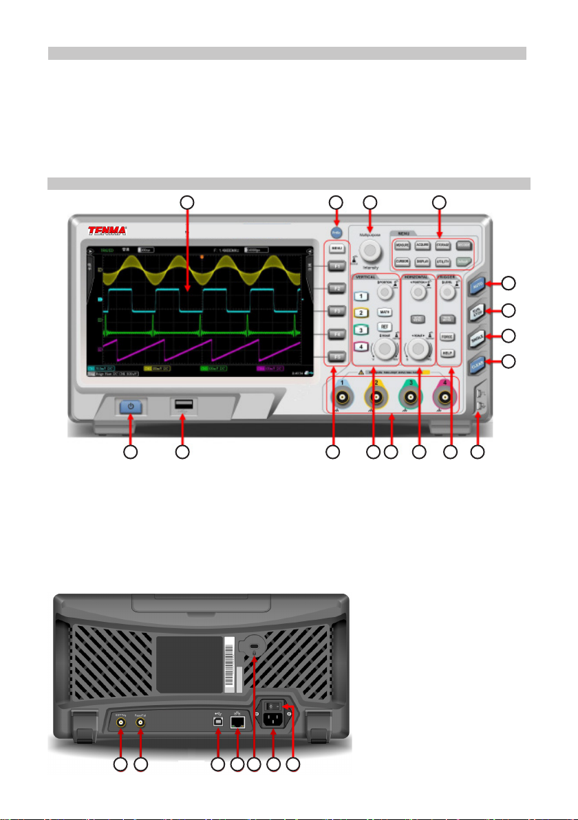
1. USB Device Identication: This icon will be displayed when an USB storage
device is connected.
2. Trigger Status Identication: Include TRIGED (has been triggered), AUTO,
READY, STOP, and ROLL (rolling)
3. Timing Scale: Indicates the amount of time represented by one square, which can
be adjusted by the horizontal scale control.
4. Sampling Rate/Acquisition Mode: Indicates the current sampling rate and storage
depth.
5. Horizontal Displacement: Shows the horizontal displacement, which can be
adjusted by turning the horizontal position control. Pressing the control returns the
displacement back to 0.
6. Trigger Status: Displays trigger source, type, slope, coupling, level, etc.
• TRIGGER SOURCE: There are seven states: CH1~CH4, AC Line, EXT, and EXT/5.
Note: CH1~CH4 will each be displayed a different trigger colour.
• TRIGGER TYPE: The types are edge, pulse width, video, slope, and advanced
trigger.
• TRIGGER SLOPE: The types are rising, falling, and rising/falling.
• TRIGGER COUPLING: The types are DC, AC, high frequency, low frequency and
noise.
• TRIGGER LEVEL: Indicates the current trigger level value, can be adjusted with the
trigger level control.
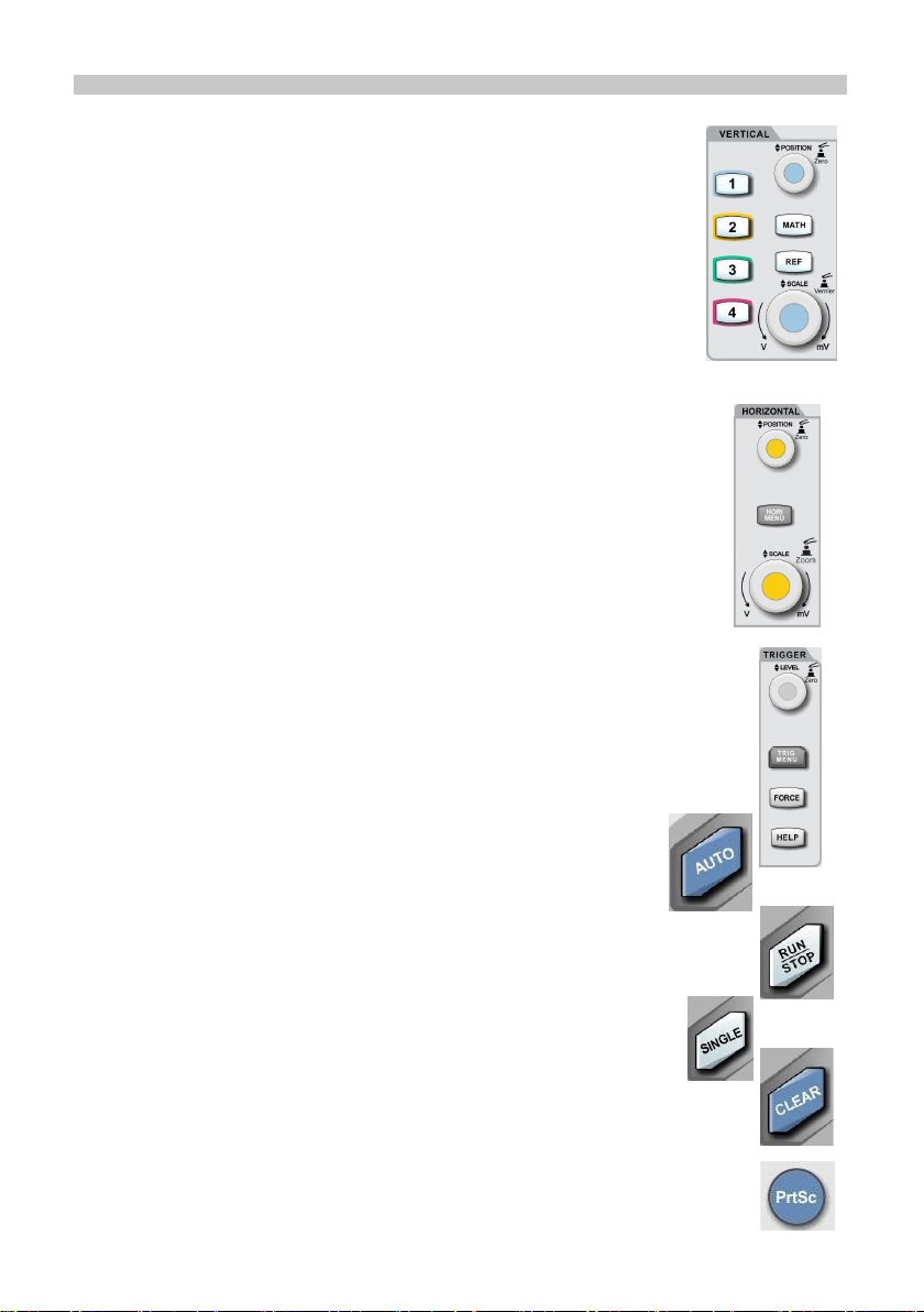
7. CH1 Vertical Identication: Displays CH1 activation state, channel coupling,
bandwidth limit, vertical prole, and probe attenuation coefcient.
• CHANNEL ACTIVATION STATE: When the background colour is consistent with
the channel colour, the channel is activated. Press CH1~CH4 to open/close the
corresponding channel.
• CHANNEL COUPLING: Includes DC, AC, and grounding.
• BANDWIDTH LIMITATION: When the bandwidth limit function is turned on, a BW
icon will appear in the display.
• VERTICAL PROFILE POSITION: When CH1 is activated, the vertical prole can be
adjusted with the vertical scale control.
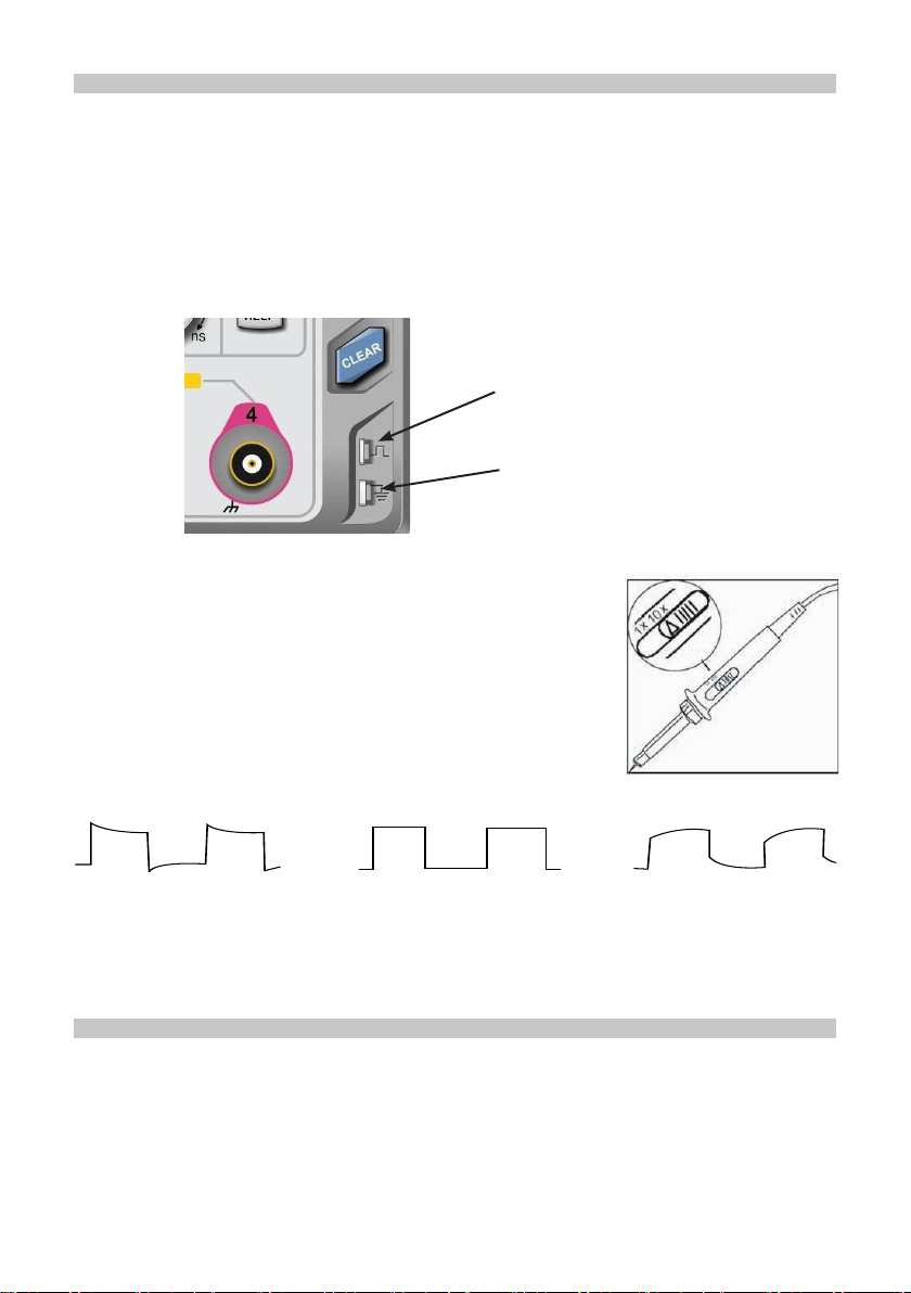
• PROBE ATTENUATION FACTOR: Displays CH1 probe attenuation coefcient:
0.001X, 0.01X, 0.1X, 1X, 10X, 100X, and 1000X
8. CH2 Vertical Identication: Same as 7 but for CH2
9. CH3 Vertical Identication: Same as 7 but for CH3
10. CH4 Vertical Identication: Same as 7 but for CH4
11. Operation Menu: Displays the current operation menu. Use F1 ~ F5 to navigate
through menu contents
12. Analogue Channels: Displays CH1~CH4 waveforms with matching tag and
waveform colour.

8
INSTRUMENT SETUP
Vertical system setup
• The 2 analogue channels are CH1 and CH2, and for 4 channel models the
channels are CH1 to CH4. Each channel should be set up individually.
• Press CH1 to CH4 and the system will display the operation menu for that channel.
• CH1~CH4 contains 3 states: open, activate, and shut down.
• Open: Allows the corresponding channel waveform to display on the screen.
• ACTIVATION: Only opened state can be activated. In the active state, the vertical
menu and the vertical control knobs (POSITION, SCALE) are for changing
activated channel setting. Any of the channels that have been opened but not
activated could be activated by the corresponding channel keys
• OFF: No waveform appears on the display.
Channel coupling setup
• If for example a signal is applied to CH1 which has a sine signal that contains DC
quantities.
• Press F1 to select AC and set up as AC coupling. Any DC quantities in the signal
are now intercepted.
Press F1 to select DC.
• Both AC and DC quantities of the signal being measured can now pass through.
• The waveform displays both AC and DC quantities of the signal.
Functions Menu Setup Notes
Coupling
AC Intercepts the DC quantities of the input signal.
DC Pass AC and DC quantities of input signal
GROUND Disconnect input signal
Bandwidth Limit On Limit bandwidth to 20MHz to reduce noise display.
Off Full bandwidth
Vertical Sensitivity
Coarse tune Coarse tune in steps of 1-2-5 to set up the
deection factor of the vertical system.
Fine tune Fine tune is further tuning within the coarse tune
set up to improve the vertical resolution.
Probe
1X, 10X,
100X and
1000X
Select either value based on the probe attenuation
factor to keep the vertical deection factor reading
correct.
Next Page Go to the second page of the channel menu
Invert On Waveform invert function on.
Off Normal waveform display.
Bias On Turns on bias function
Off Turns off the bias function
Bias Voltage Adjust with the multi purpose control, the bias
voltage is used to offset the DC voltage the signal
Return to Zero Returns the bias voltage back to 0V
Return Return to the rst page of the channel menu

9
Channel bandwidth setup
• If for example a signal is applied to CH1 which is a pulse signal that contains high
frequency oscillation.
• Press CH1 to select Channel1.
• Press F2 to set the BANDWIDTH LIMIT OFF so it is set up as full bandwidth.
• The signal being measured can now pass through even if it contains high frequency
quantities.
• Press F2 to set BANDWIDTH LIMIT ON so that frequency quantities higher than
20MHz in the signal being measured will be limited.
Probe rate setup
• To match the probe attenuation factor setup, it is necessary to set up the probe
attenuation factor in the channel operation menu accordingly.
• For example when the probe attenuation factor is 10:1, set the probe attenuation
factor at 10X in the menu. This principle applies to other values to ensure the
voltage reading is correct.
• The coefcients can be set to 0.001X, 0.01X, 0.1X, 1X, 10X, 100X, and 1000X.
Waveform inversion (Reverse Phase)
• The displayed signal is inverted 180 degrees with respect to the ground level.
• The vertical identication will display a reverse phase logo ↓.
Vertical Volts/Div adjustment setup
• The VOLTS/DIV range of the vertical deection factor can be adjusted either in
coarse or ne tune mode.
• In COARSE TUNE the VOLTS/DIV range is 1mV/div~2V/div. Tuning is in steps of
1-2-5. For example: 10mV - >20mV - >50mV - >100mV.
• In FINE TUNE mode it adjusts in 1% of the current amplitude value steps.
For example: 10.00mV—>10.10mV—>10.20mV—>10.30mV.
• Press F1 to select GROUND.
Both AC and DC quantities of the signal being measured are now intercepted.
• The waveform is not displayed in this mode but the signal remains connected to the
channel circuit.

10
Bias
• When the amplitude of the DC component in the signal is relatively large, waveform
observation could be very inconvenient.
• Using the bias function and the superposition of a -10V bias voltage can eliminate
the DC component of the waveform so the AC signal can be clearly observed.
Setting up the Trigger system
• Triggering decides when the oscilloscope collects data and displays waveforms.
Once the trigger is correctly set up, it can convert unstable display into signicant
waveforms.
• When beginning to collect data the oscilloscope rst collects sufcient data to draw
a waveform on the left of the triggering point.
• While waiting for the triggering condition to occur it will continuously collect data.
When sufcient data is acquired to draw a waveform on the right of the triggering
point.
Trigger Source - Trigger can be obtained from various sources: Input channel (CH1,
CH2, CH3 or CH4), external trigger (EXT, EXT/5) or Line A/C etc.
1. Input channel - the most common trigger source is input channel. The selected
trigger source can operate normally whether the input is displayed or not. Select
any one of the analogue signal input terminal CH1~CH4 on the front panel of the
oscilloscope as a trigger signal.
2. External trigger - Select the input Trig EXT from the back of the oscilloscope. For
example, the external clock input can be used on the Trig EXT terminal as a trigger
source. EXT signal trigger level ranges from -1.8V~ +1.8V can be set. The EXT/5
trigger signal divides the actual signal by 5, so the trigger level can be increased to
-9V ~ +9V.
3. AC Line - Power supply signal, used to observe the relationship between power
signals such as lighting equipment and power supply equipment, to obtain stability
in synchronization.
Trigger Mode - determines the action of the oscilloscope when there is no trigger. There
are three trigger modes - auto, normal and single.
1. Auto Trigger - samples the waveform data when there is no trigger signal input.
The scan base is shown on the display. When the trigger signal is generated it
automatically turns to trigger scan for signal synchronisation.
Note: when the time base of the scan waveform is set to 50ms/div or slower, the auto
mode allows no trigger signal.

11
2. Normal Trigger - In this mode waveforms are only sampled when triggering
conditions are met. The system stops acquiring data and waits when there is no
trigger signal. When a trigger is generated, trigger scan occurs.
3. Single Trigger - In this mode press RUN button once and the oscilloscope will wait
for trigger. When one trigger is detected, it will sample and display the acquired
waveform, then stop.
Trigger coupling - determines which quantities of the signal are transmitted to the
trigger circuit. Coupling modes are DC, AC, low frequency reject and high frequency
reject.
1. DC - allowing all quantities to pass.
2. AC - intercepting DC quantities and attenuating signals under 10Hz.
3. Low Frequency Reject - Intercepting DC quantities and attenuating low frequency
quantities under 80kHz.
4. High Frequency Reject - Attenuating high frequency quantities over 50kHz.
Pre-Trigger/Delayed Trigger - data sampled before/after triggering. The trigger position
is typically set at the horizontal centre of the screen. You are able to view ve divisions
of pre-trigger and delayed trigger information. Use the horizontal position control to
adjust the horizontal shift of the waveform to see more pre-trigger information.
Forced Trigger
Press the FORCE key to generate a forced trigger signal.
If the waveform is not displayed in normal or single shot mode, press the FORCE button
to collect the signal baseline to ensure acquisition is normal.
Edge Trigger:
• When selecting edge trigger, you are triggering at the rising and falling edges of the
input signal.
• Press TRIG MENU and press F1 to select the trigger type and use the multifunction
control to conrm.
Functions
Menu Setup Notes
Type Edge
Signal source
selection
CH1 to CH4
EXT, EXT/5
AC Line
Set Ch1 to CH4 as the signal source trigger signal
Set the external trigger input channel as the signal source
trigger signal
Set AC line as trigger
Grid
Alternate
Set up as grid trigger
Ch1, CH2 trigger their own signals alternatively
Inclination Rising
Falling
Set to trigger on the signals rising edge
Set to trigger on the signals falling edge
Trigger Mode
Auto
Normal
Single
Set to sample waveform only if no trigger condition is detected
Set to sample waveform only if trigger condition is satised
Set to sample waveform once when detecting one trigger and
then stop
Trigger coupling
DC
AC
H/F reject
L/F reject
Noise
Suppression
Intercept DC quantities of the input signal
Allow AC and DC quantities of the input signal to pass
Reject high frequency quantities above 50kHz of the signal
Reject low frequency quantities below 5kHz of the signal
Suppress the noise of the trigger signal, trigger sensitivity is
halved.

12
Pulse Trigger
• Pulse trigger means determining the triggering time based on the pulse width. You
can acquire abnormal pulse by setting the pulse width condition.
• Press the TRIG MENU button then press F1 to select trigger type and then set the
pulse width using the multi-purpose control.
Functions Menu Setup Notes
Type Pulse
Trigger source
CH1 to CH4
EXT, EXT/5
AC Line
Set Ch1 to CH4 as the signal source trigger signal
Set the external trigger input channel as the signal
source trigger signal
Set AC line as trigger
Pulse width
condition
Larger
Smaller
Equal
Trigger when pulse width is larger than default value
Trigger when pulse width is smaller than default value
Trigger when pulse width equals to default value
Pulse width setting 4.0ns~10.0s The pulse width time can be set from 4.0ns~10.0s using
the multi-purpose control
Trigger polarity Pos pulse width
Neg pulse width
Set positive pulse as the trigger signal
Set negative pulse width as the trigger signal
Trigger mode
Auto
Normal
Single
The system automatically samples waveform data
when there is no trigger signal input. The scan baseline
is shown on the display. When the trigger signal is
generates it automatically turns to trigger scan.
The system stops acquiring data when there is no
trigger signal. When the trigger signal is generated
trigger scan occurs.
One trigger will occur when there is an input trigger
signal. Then trigger will stop.
• PULSE WIDTH: The time difference between the trigger level and the positive
pulse is dened as the positive pulse width, and the time difference between the
trigger level and the negative pulse is dened as the negative pulse width, shown in
the following diagram.
Video Trigger
• The waveform of the video signal includes the image signal and the time sequence
signal, and each kind of signal uses different standards and formats.
• Basic measurement functions, which can be triggered in NTSC, SECAM, PAL, and
other standard video formats.
• Press the TRIG MENU, Press F1 to select the trigger type, then set to video trigger
using the multi-purpose control.

13
Slope Trigger
• When slope trigger is selected, trigger occurs when the rise or fall slope value
matches the value in settings.
• Press the TRIG MENU, Press F1 to select the trigger type, then set to slope trigger
using the multi-purpose control.
Functions
Menu Setup Notes
Type Video
Trigger source
CH1 to CH4
EXT, EXT/5
AC Line
Set Ch1 to CH4 as the signal source trigger signal
Set the external trigger input channel as the signal source
trigger signal
Set AC line as trigger
Standard
PAL
NTSC
SECAM
Uses PAL format video signals
Uses NTSC format video signals
Uses SECAM format video signals
Synchronisation
All lines
Specied
lines
Odd eld
Even eld
Set the TV line to synchronise with trigger
Set synchronised trigger on the specied line and adjust by
turning the multifunction control on the front panel
Set video odd eld to synchronised trigger
Set video even eld to synchronised trigger
Functions
Menu Setup Notes
Type Slope
Trigger source CH1 to CH4 Set Ch1 to CH4 as the signal source trigger signal
Trigger Setting Enters trigger setting menu
Slope Setting Enters slope setting menu
Slope Falling
Rising
Triggers with falling slope
Triggers with rising slope
Condition
<
>
=
When slew rate setting is smaller than signal slew rate, trigger occurs
When slew rate setting is greater than signal slew rate, trigger occurs
When slew rate setting is equal to signal slew rate, trigger occurs
Time Setting Use the multi-purpose control to set time, the slew rate shown
on bottom of the screen also changes
Video Line Sync Video Field Sync

14
Threshold
Low
High
High
and Low
The slope of the low threshold level can be adjusted with the
LEVEL control
The slope of the high threshold level can be adjusted with the
LEVEL control
The slope of the high and low threshold level can be adjusted
with the LEVEL control
Slew Rate = (High threshold level – Low threshold level) / Time
RS232 Trigger and Decode (Optional)
• Press the DECODE button at the right corner, choose the TYPE option to open
the protocol type list. Rotate the multi-purpose control to select to RS232 protocol
mode, and press the control to open the RS232 protocol mode.
• TRIGGER SOURCE: Select the Source Channel
• Select this option and the source font will become green. Press any signal source
button to switch between CH1-CH4 as the source. The appropriate logic level can
be adjusted when the corresponding signal source is selected. The way to adjust
the signal level is the same with adjusting the trigger level.
• To avoid the effect of noise, it is suggested to set the level compare at the
waveform centre area to obtain accurate results.
• TRIGGER SETTING: Set the Trigger Selection
• Select this option to enter the trigger setting menu. The Trigger Mode can be set
to Auto or Normal. The Trigger Coupling can be set to DC, AC, low frequency, high
frequency suppression, or noise suppression. Select RETURN to return to the
previous menu.
• BIT SETTING: Set the Data Bit
• Select this option to enter the bit setting interface.
• DATA BIT WIDTH SETTING: Select DATA BIT WIDTH SETTING, and the data bit
width selection list will pop up.
• Press the DATA BIT WIDTH SETTING selection key again to switch between
5/6/7/8 bits. The data bit width can also be selected using the multifunction control.
• Press the control to conrm the selected data bit width.

15
• DATA SETTING: Rotate the knob under the bit setting interface to set the data. The
upper and lower bounds of the data
are directly related to the data bit width.
■ 5-bit corresponds to 0——31
■ 6-bit corresponds to 0——63
■ 7-bit corresponds to 0——127
■ 8-bit corresponds to 0——255
• STOP BITS SETTING: Select the STOP BITS option to open the stop bits selection
list.
• Press the STOP BITS option key again to switch between 1 or 2 bits.
• The Multi-purpose control can also be used for this function.
• PARITY BIT SETTING: Select the PARITY BITS option under the bit setting
interface, and the parity selection list will pop up.
• Press the PARITY BIT option key again to switch between zero, odd, and even.
Zero means no parity. Even and odd mean even parity and odd parity respectively.
• The Multi-purpose control can also set the parity bit.
• Press the RETURN option button key to return to the previous menu.
• Press NEXT PAGE key to enter the following settings:
• CONDITION: Trigger Condition Settings
• There are four kinds of trigger methods: Start of frame, error frame, parity error, and
data.
• Press the CONDITION option button and the trigger condition list will pop up.
• Press the CONDITION button again to switch between the four modes.
• The Multi-purpose control can also set the trigger condition.
• START OF FRAME: The waveform trigger is at the start bit of the RS232 protocol
(referred to the drawing). Stable waveforms can be observed by choosing the start
of frame when single string signals or multiple same string signals are sent. If the
data being sent is changing, the waveform will also change correspondingly.
• PARITY ERROR: Set the RS232 parity bit to 0 or 1 according to the parity
principles, the principles are as follows:
• ODD PARITY: If the 1st bit is odd for data bit and parity bit, the transmission will be
correct.
• EVEN PARITY: If the 1st bit is even for data bit and parity bit, the transmission will
be correct.
This function can quickly check the transmission process with parity error during
RS232 communication, for ease of analysing and locating faults.
• ERROR FRAME: The error frame can be classied to two kinds. One is parity
error (odd or even error), the other is transmission error. The transmission error
conditions are as follows:
1. The signal is not set to 1 where there should be stop bits, then the frame
data is wrong.
2. When signals suddenly change and become unstable, this function can
quickly test for transmission errors.
• DATA: The waveform triggers when the data of BIT SETTING menu is equal to the
data the oscilloscope is collecting. Note that the data setting range is related to the
data bit width. This function can quickly nd the transmitting signals of particular
data set.

16
• POLARITY: Set the signal polarity.
• Normally, the positive polarity is used in RS232 protocol. The high level and low
level stands for logic 1 and 0 respectively. Some users might use negative polarity,
which is that the high level and low level stands for 0 and 1 respectively. Therefore,
the design is optimized to meet demands from different users.
Choose the POLARITY option key, and the polarity selection list will pop up. Press
the POLARITY option key again to switch between positive polarity and negative
polarity. The Multi-purpose can also be used.
• BIT SEQUENCE: Set the data bit sequence
• Normally, the lower bit is transmitted rst in RS 232 communication. For example:
if bit [7:0] is transmitted, the bit [0] will be transmitted rstly, and bit [7] transmitted
last. Considering that users probably use MSB, that is, bit [7] is rstly. The
transmitting methods can be set by users.
Select the Bit Sequence option key, and the bit sequence selection list will pop up.
Press the bit sequence again to switch between LSB and MSB. The Multi-purpose
knob can also be used.
• BAUD RATE: Set the transmitting baud rate.
• There are no clock signals for asynchronous serial communication. In order to
analyse the data, the two communication parties need to agree on the baud rate.
• Press the BAUD RATE option key, and the baud rate selection list pops up. Press
the BAUD RATE key again to switch between different baud rates. The available
baud rates are: 2400bps, 4800bps, 9600bps, 19200bps, 38400bps, 57600bps,
115200bps, and customized. The customized baud rate can be set from 1 to
5000000 (5 million).
• After selecting the customized baud rate, the customized value can be adjusted
using the Multi-purpose control. Press the corresponding baud rate display button
to increase the baud rate digit being controlled in order to quickly set to the desired
baud rate.
• It is recommended that the interface length should be less than 20m and with speed
below 1Mbps. Outside of these ranges and the communication can be unreliable.
• If a more detailed communication analysis is needed, the protocol decoding
function can be used. Oscilloscopes will capture the continuous communication
data for you when using this function. The communication contents can be shown
on screen or in the event list.
• BUS SETTING: Press the PRESS SETTING option key to enter the decoding bus
setting.
• BUS STATUS: Press the BUS STATUS option key, and the bus control selection list
pops up. The decoding function can be open or closed. The Multi-purpose knob can
also be used.
• DISPLAY FORMAT: Press the DISPLAY FORMAT option key, and four kinds of
display methods can be used: hexadecimal, decimal, and binary, and ASCII. The
Multi-purpose control can also be used.
• EVENT LIST: Press the EVENT LIST option key, and the decoding events can be
open or closed. The Multi-purpose control can also be used.
• PSEUDO SQUARE WAVE: Press the PSEUDO SQUARE WAVE option key, and
the pseudo square wave function can be opened and closed. The Multi-purpose
control can also be used. The pseudo square wave displays 0/1 collected by
the oscilloscope. The function can display logic 0 and 1 on the screen under the
condition that the input waveform is severely distorted.

17
• Press the NEXT PAGE option key to enter the following settings:
• VERTICAL POSITION: Press the VERTICAL POSITION option key and rotate the
Multi-purpose control to adjust the position of decoding data on the screen.
• EVENT LIST CHECK: When the Oscilloscope is in the state of decoding, the RUN/
STOP button is green. At this moment, press the RUN/STOP and the Oscilloscope
will stop refreshing waveform and the button will turn red. The collected data will be
stored in the Oscilloscope. The menu will display decoding data selection list, the
button can display the captured times of transmission signals and the number the
selected data.
• The selected decoding data will be highlighted green. The Multi-purpose control can
select any collected data.
Input signals are shown in gure below: data width is 8 bits, data bit is 0*55, and stop bit
is 1 bit, even parity. The trigger condition is: data, negative polarity, the bit sequence is
LSB, the baud rate is 115200bps.
The bus settings are: Bus is open, the display format is ASCII, event list open.
I2C Protocol Trigger and Decode (Optional)
• I2C protocol is usually used to connect micro-controller and its peripheral
equipment, a widely used protocol in the eld of microelectronics communication
control. The bus protocol uses two wires to transmit.
• One is serial data cable SDA, the other is serial clock cable.
I2C Start Trigger
• Press the DECODE button. Then press the TYPE option key to open protocol type
list. Rotate Multi-purpose control to select the SPI protocol mode. Press Multi-
purpose control to start the SPI protocol mode.
• SCL: Select clock source
Press this option key and the present clock source font becomes green. Press the
SCL button again to switch any channel among CH1-CH4 as clock source. The
corresponding logic level can be adjusted when the corresponding signal source
is selected. The way of adjusting is the same with that of trigger level. To avoid the
effect of signal noise, it is suggested that the comparative level should be set in the
waveform centre area to obtain accurate results.

18
• Press the SCLK EDGE button to set the clock source as rising edge or falling edge.
• SDA: Select data source
Press this option key and the present clock source font becomes green. Press the
SDA button again to switch any channel among CH1-CH4 as clock source. The
logic level can be adjusted when the corresponding signal source is selected. The
way of adjusting is the same with that of trigger level. To avoid the effect of signal
noise, it is suggested that the comparative level should be set in the waveform
centre area to obtain the accurate captured result.
• CONDITION: Trigger Condition Selection
• Press this option button and the trigger timing selection will display. The following
are the trigger timing conditions:
1. START: Trigger at the starting moment. Namely, SDA occurs at falling edge when
SCL is at logic high. Note that the restarting state is stored in I2C, the starting signal
can occur again (restart) before rst signal’s stop signal. Both the start and the
restart can produce a trigger signal.
2. RESTART: Triggers at the restarting moment. When a start signal occurs before the
previous signal ends, this situation is dened as restart signal.
3. STOP: Triggers when the stop bit occurs. Namely, SDA goes from low to high when
SCL is high.
4. LOSS: It is the loss conrmation trigger. Every time after 8 bits are transmitted
in I2C protocol, the data receiver transmits the receiving signal, which is the
answering bit in gure above. The SDA signal is low and SCL high. The loss
conrmation trigger occurs on the receiving bit, when SCL and SDA and both high.
5. ADDR: It is address trigger. The address trigger will occur if the communication
address is the same with the user setting address. It can help to quickly locate
using address.
6. DATA: It is data trigger. The data trigger can occur with the following conditions:
equal/greater/less/unequal. It is convenient to analyse data and capture abnormal
data.
7. ADDR DATA: It is address data trigger. The trigger occurs when the addresses
are the same during transmitting and the data satises the setting condition. It is
convenient to realize the I2C specied address trigger and data trigger, and help
analyse the transmission.
• Press the NEXT PAGE function key to enter additional I2C trigger settings:
Address Setting
• Press the ADDR button to set the related address information.
• WIDTH: It is the address width selection. Press this option button and the address
width selection list pops up. Press the WIDTH function button again to select 7 or
10 bits width. Rotating the multi-purpose control can also select the width. Press
the multi-purpose control to conrm selection.
• ADDRESS: Within this interface, directly rotate the multi-purpose control to set the
address value. Note that the set value is related to the present bit width. The seven
bit address can be set from 0x0 to 0x7F and the ten bit address can be set from
0x0 to 0x3FF.
• DIRECTION: Set the read-write direction. Select this option and the read/write
selection list will pop up. Press the read/write option key to switch between each
other. After the selection list pops up, the multi-purpose control can also be used.
Press the multi-purpose control to conrm selection.

19
Data Setting
• Select this option to set the related data information.
• BYTE: Set the data byte. Select this option and the data byte selection list pops up.
Press the button again to switch between 1, 2, 3, 4, and 5 bytes. The multi-purpose
control can also be used.
• BIT: Select the bit. Directly rotate the multi-purpose control to select the bit under
the data set interface. The selected bit will be highlighted red at the bottom left
corner
Note: the selected bits are directly related to the set bytes. For example, the bit of 0 to 7
can be selected if 1 byte is set.
• DATA BIT: Set every bit of data. The present data bit can be set to H/L as required.
The bottom left corner will display the present data setting condition, and the value
can be set with hexadecimal and MSB method.
• All Bits: Set the entire bit to the same value. It is helpful to quickly set the value and
reset. Press the NEXT PAGE option key to enter additional I2C trigger settings.
• DATA CONDITION: Use this option to set the relation between the captured and set
data when data is triggering. The captured data can be set to equal, greater, or less
than the set data.
• TRIGGER SETTING: Set the trigger selection.
Use this option to enter the trigger setting menu. The trigger mode can be set to
auto or normal. The trigger coupling can be set to: DC, AC, low frequency, high
frequency suppression, and noise suppression. Press the RETURN to return to the
previous menu.
• If a more detailed communication analysis is needed, the native protocol decoding
function can be used. The oscilloscope will capture the continuous communication
data which can be displayed directly by the screen or in the event list to make
communication analysis quicker, more accurate, and more convenient.
• BUS SETTING: Use this option to enter decode bus settings:
• BUS STATUS: Use this function to enable bus control selection list, to open or close
the decoding function. You can also operate using the multi-purpose control after
the selection list pops up.
• DISPLAY FORMAT: Use this feature and the display format can be switched
between hexadecimal, decimal, and binary. The multi-purpose control can also be
used after the selection list pops up.
• EVENT LIST: The event list can be open or closed using this feature. We can also
operate through the multi-purpose control. The event list contains the decoded
data for continuous collection which can be directly displayed on the screen, which
contains data capture time, data content, and parity status
• PSEUDO SQUARE WAVE: The pseudo wave function can be open or closed using
this feature. The multi-purpose control can also be used after opening the function
list. The waveform is displayed using the 0/1 collected by the oscilloscope. This
feature is useful when the input wave is severely distorted.
• VERTICAL POSITION: Use this feature and rotate the multi-purpose control to
adjust the position of decoded data on the screen.
• Event List Check: When the oscilloscope is in the state of decoding, RUN/STOP
is green. At the moment when pressing RUN/STOP, RUN/STOP is red. The
oscilloscope will stop refreshing waveform and the collected data will be stored in
the oscilloscope. The menu will display decoded data selection.
The button displays the times of captured transmission signal and the

20
corresponding number of the present selected data. The selected decoding data will
be highlighted green. The multi-purpose control can select any collected data. This
function can nd the content of captured multiple transmission communication and
help to debug the system conveniently.
• Input the signal as shown the gure below. The oscilloscope is set up as follows.
SCL selection is CH1. SDA selection is CH2. The condition is Addr. The set address
is 7bits, 0x48 and the direction is writing. The data do not need to be set because
data trigger is used.
• The bus status is open during setting the bus. The displayed format is ASCII. Open
the event selection and the display is as follows:
SPI Protocol Trigger and Decode (Optional)
• SPI interface is a kind of synchronized serial peripheral interface, which can make
the host and all kinds of peripheral equipment undertake communication through
the serial methods. It is a kind of synchronous communication bus of full duplex.
It usually uses four signal lines: MOSI: the host data output, the slave data input;
MISO: the host data input, the slave output; SCLK: time signal the host transmits;
CS: the slave chip selection enable signal.
• SPI interface is mainly used to transmit the serial data between the host and low
speed peripheral devices. The data are transmitted according to the bit, that is to
say, higher bit rst and then lower bit. SPI interface do not need look for the slave
address. The communication is of full duplex and the protocol itself is easier. So it is
widely used. SPI protocol transmission is shown in the following diagram:
This manual suits for next models
3
Table of contents
Other Tenma Test Equipment manuals

Tenma
Tenma 72-3565 User manual

Tenma
Tenma DSO Series User manual

Tenma
Tenma DSO User manual

Tenma
Tenma 72-3575 User manual

Tenma
Tenma 72-9405 User manual

Tenma
Tenma 72-2650 User manual

Tenma
Tenma TEN01057 User manual

Tenma
Tenma 72-7615 User manual

Tenma
Tenma 72-7910 User manual

Tenma
Tenma 72-7985 User manual

Tenma
Tenma 72-6694 User manual

Tenma
Tenma 72-6947 User manual

Tenma
Tenma 72-2650 User manual

Tenma
Tenma 72-7630 User manual

Tenma
Tenma 72-2680 User manual

Tenma
Tenma 72-490 User manual

Tenma
Tenma 72-2665 User manual

Tenma
Tenma 72-8710 User manual

Tenma
Tenma 72-9355 User manual

Tenma
Tenma 72-9400A User manual