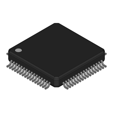
Toshiba TC9314F User manual
Other Toshiba Microcontroller manuals

Toshiba
Toshiba TXZ+ Series User manual

Toshiba
Toshiba TXZ SERIES User manual
Toshiba
Toshiba H1 Series Product guide

Toshiba
Toshiba TXZ Family User manual
Toshiba
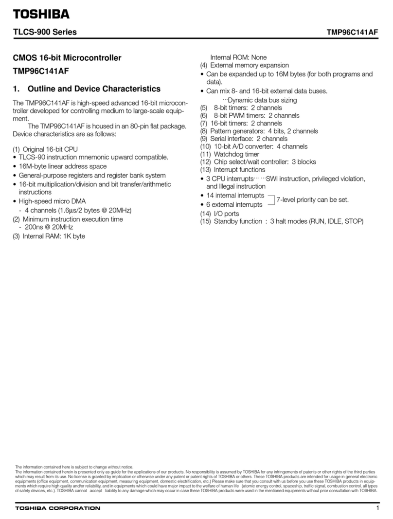
Toshiba TMP96C141AF User manual

Toshiba
Toshiba TXZ SERIES User manual

Toshiba
Toshiba TLCS-900/L1 Series User manual
Toshiba
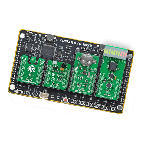
Toshiba TMPM4K User manual
Toshiba
Toshiba TMP91C815F Product guide
Toshiba
Toshiba TX79 Series User manual

Toshiba
Toshiba TLCS-900/H1 Series Product guide

Toshiba
Toshiba TLCS-900/H1 Series User manual
Toshiba
Toshiba TXZ Plus Series User manual

Toshiba
Toshiba TXZ SERIES User manual

Toshiba
Toshiba TLCS-900/L1 Series User manual

Toshiba
Toshiba TXZ+ Series User manual
Toshiba
Toshiba TMPM3H User manual

Toshiba
Toshiba TLCS-900/H1 Series User manual

Toshiba
Toshiba T6K04 User manual

Toshiba
Toshiba TLCS-90 Series Product guide
Popular Microcontroller manuals by other brands

Novatek
Novatek NT6861 manual

Espressif Systems
Espressif Systems ESP8266 SDK AT Instruction Set

Nuvoton
Nuvoton ISD61S00 ChipCorder Design guide

STMicrolectronics
STMicrolectronics ST7 Assembler Linker user manual

Texas Instruments
Texas Instruments Chipcon CC2420DK user manual

Lantronix
Lantronix Intrinsyc Open-Q 865XR SOM user guide
