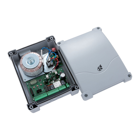
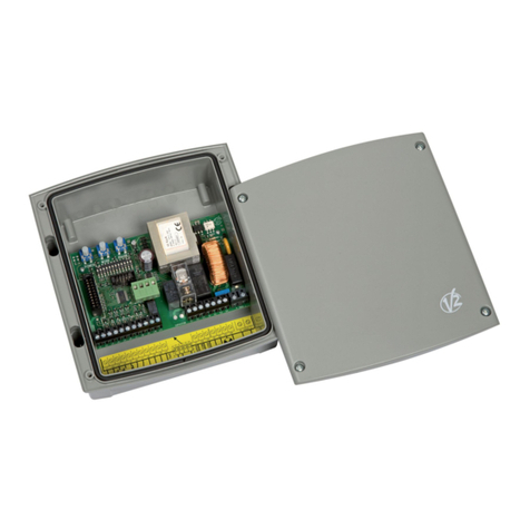
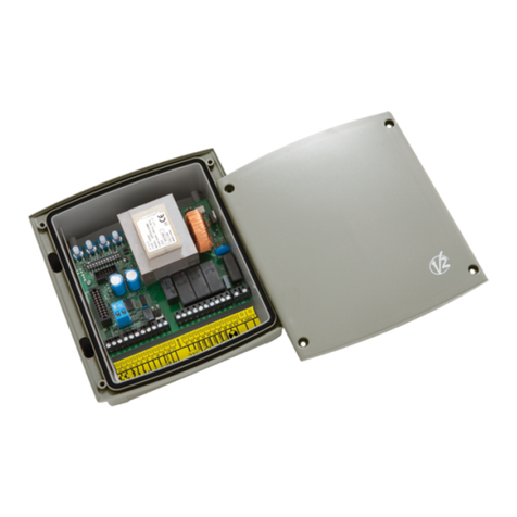
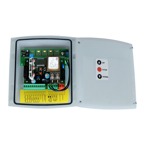
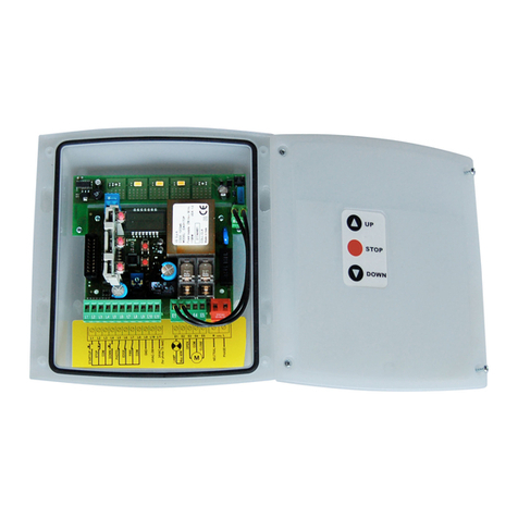
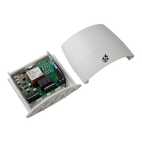
V2 EASY-BASIC User manual

ZIS365
IL 398
EDIZ. 14/11/2018
I
CENTRALE DI COMANDO
ANALOGICA PER SERRANDE
AVVOLGIBILI
GB
ANALOG CONTROL UNIT FOR
ROLLER SHUTTERS
F
ARMOIRE DE COMMANDE
ANALOGIQUE POUR STORES
E
CUADRO DE MANIOBRAS
ANALÓGICO PARA PERSIANAS
ENROLLABLES
P
QUADRO ELÉCTRICO ANALÓGICO
PARA ESTORES DE ENROLAR
D
ANALOGE STEUERUNG
FÜR ROLLTORE
NL
ANALOGE STUURCENTRALE
VOOR ROLLUIKEN
EASY-BASIC


ITALIANO
- 1 -
AVVERTENZE IMPORTANTI
Per chiarimenti tecnici o problemi di installazione contatta il
Servizio Clienti V2 al Numero Verde 800-134908 attivo dal
lunedì al venerdì dalle 8:30 alle 12:30 e dalle 14:00 alle 18:00
V2 S.p.A. si riserva il diritto di apportare eventuali
modifiche al prodotto senza preavviso; inoltre declina ogni
responsabilità per danni a persone o cose dovuti ad un uso
improprio o ad un’errata installazione.
mLeggere attentamente il seguente manuale di
istruzioni prima di procedere con l’installazione e la
programmazione della centrale di comando.
• Il presente manuale di istruzioni è destinato solamente a
personale tecnico qualificato nel campo delle installazioni di
automazioni.
• Nessuna delle informazioni contenute all’interno del manuale
può essere interessante o utile per l’utilizzatore finale.
• Qualsiasi operazione di manutenzione o di programmazione
deve essere eseguita esclusivamente da personale qualificato.
L’AUTOMAZIONE DEVE ESSERE REALIZZATA IN CONFORMITÀ
VIGENTI NORMATIVE EUROPEE:
EN 60204-1 (Sicurezza del macchinario, equipaggiamento
elettrico delle macchine, parte 1: regole generali).
EN 12445 (Sicurezza nell’uso di chiusure automatizzate,
metodi di prova).
EN 12453 (Sicurezza nell’uso di chiusure automatizzate,
requisiti).
• L’installatore deve provvedere all’installazione di un dispositivo
(es. interruttore magnetotermico) che assicuri il sezionamento
onnipolare del sistema dalla rete di alimentazione. La normativa
richiede una separazione dei contatti di almeno 3 mm in
ciascun polo (EN 60335-1).
• Una volta effettuati i collegamenti sulla morsettiera, è
necessario mettere delle fascette rispettivamente sui conduttori
a tensione di rete in prossimità della morsettiera e sui
conduttori per i collegamenti delle parti esterne (accessori).
In tal modo, nel caso di un distacco accidentale di un
conduttore, si evita che le parti a tensione di rete possano
andare in contatto con parti a bassissima tensione di sicurezza.
• Per la connessione di tubi rigidi e flessibili o passacavi utilizzare
raccordi conformi al grado di protezione IP55 o superiore.
• L’installazione richiede competenze in campo elettrico e
meccanico; deve essere eseguita solamente da personale
qualificato in grado di rilasciare la dichiarazione di conformità
di tipo A sull’installazione completa (Direttiva macchine
89/392 CEE, allegato IIA).
• E’ obbligo attenersi alle seguenti norme per chiusure veicolari
automatizzate: EN 12453, EN 12445, EN 12978 ed alle
eventuali prescrizioni nazionali.
• Anche l’impianto elettrico a monte dell’automazione deve
rispondere alle vigenti normative ed essere eseguito a regola
d’arte.
• La regolazione della forza di spinta dell’anta deve essere
misurata con apposito strumento e regolata in accordo ai valori
massimi ammessi dalla normativa EN 12453.
• Collegare il conduttore di terra dei motori all’impianto di messa
a terra della rete di alimentazione.
• Osservare le necessarie precauzioni (esempio bracciale
antistatico) nel maneggiare le parti sensibili alle scariche
elettrostatiche.
DICHIARAZIONE DI CONFORMITÀ
V2 S.p.A. dichiara che i prodotti EASY-BASIC sono conformi ai
requisiti essenziali fissati dalle seguenti direttive
- 2014/30/UE (Direttiva EMC)
- 2014/35/UE (Direttiva Bassa Tensione)
- 99/05/CEE (Direttiva Radio secondo le norme EN 301 489-3)
- ROHS2 2011/65/CE
Racconigi, lì 01/06/2016
Il rappresentante legale della V2 S.p.A.
Antonio Livio Costamagna
SMALTIMENTO
Come per le operazioni d’installazione, anche al termine della
vita di questo prodotto, le operazioni di smantellamento devono
essere eseguite da personale qualificato.
Questo prodotto è costituito da vari tipi di materiali: alcuni
possono essere riciclati, altri devono essere smaltiti.
Informatevi sui sistemi di riciclaggio o smaltimento previsti dai
regolamenti vigenti nel vostro territorio, per questa categoria di
prodotto.
Attenzione! – Alcune parti del prodotto possono contenere
sostanze inquinanti o pericolose che, se disperse nell’ambiente,
potrebbero provocare effetti dannosi sull’ambiente stesso e
sulla salute umana. Come indicato dal simbolo a lato, è vietato
gettare questo prodotto nei rifiuti domestici. Eseguire quindi la
“raccolta separata” per lo smaltimento, secondo i metodi previsti
dai regolamenti vigenti sul vostro territorio, oppure riconsegnare
il prodotto al venditore nel momento dell’acquisto di un nuovo
prodotto equivalente.
Attenzione! – i regolamenti vigenti a livello locale possono
prevedere pesanti sanzioni in caso di smaltimento abusivo di
questo prodotto.

ITALIANO
- 2 -
DESCRIZIONE DELLA CENTRALE
La centrale EASY-BASIC è un innovativo prodotto V2 che
garantisce sicurezza ed affidabilità per l’automazione di serrande
avvolgibili.
• Regolazioni e programmazione tramite trimmer e dip switch
• Alimentazione per 1 motore monofase 230V
• Ricevitore 433,92 MHz incorporato
• Funzionamento con trasmettitori serie Personal Pass o Royal:
il primo telecomando che viene memorizzato determina la
modalità di funzionamento Royal o Personal Pass
• Possibilità di memorizzare 30 codici diversi (Personal Pass)
• Ingressi di start, stop / costa
• 1 ingresso per fotocellule
• Ingresso di STOP, utilizzabile anche per controllare una costa
resistiva (jumper J1 NON inserito)
• Gestione di start da trasmettitore
• Uscita 230V per lampeggiante o luce di cortesia
• Monitoraggio dello stato ingressi tramite led
CARATTERISTICHE TECNICHE
Modelli 230V Modelli 120V
Alimentazione 230 V / 50 Hz 120V / 60Hz
Carico max motore 1100 W 600 W
Carico max accessori
alimentati a 24 VAC
3 W
Temperatura di lavoro -20 ÷ +60 °C
Fusibile di protezione F1 = 5A delayed
F2 = 160 mA delayed
Dimensioni 170 x 185 x 70 mm
Peso 800 g
Protezione IP55
COLLEGAMENTI ELETTRICI
H1 Centrale antenna
H2 Schermatura antenna
H3 START. Contatto N.A.
H4 STOP. Contatto N.C.
(pulsante di STOP - J1 inserito)
EDGE
(costa di sicurezza resistiva - J1 NON inserito)
L’intervento della costa di sicurezza disabilita la
chiusura automatica.
H5 COMUNE (-)
H6 FOTOCELLULA. Contatto N.C.
H7-H8 Uscita alimentazione 24 Vac per fotocellule ed altri
accessori
E1 - E2
Lampeggiante 230Vac / 120Vac
Luce di cortesia 230Vac / 120Vac
E3 Apertura motore
E4 Comune motore
E5 Chiusura motore
NNeutro alimentazione 230Vac / 120Vac
LFase alimentazione 230Vac / 120Vac

ITALIANO
- 3 -
PROG
F2
F1
WORK
Rx
PAUSE
H1 H2 H3 H4 H5 H6 H7 H8 E1 E2 E3 E4 E5 N L
START STOP PHOTO
J1
1 2 3 4 5 6
START
PHOTO
STOP / EDGE
COM
24 VAC-3W
COM
LAMP
OPEN
COM
CLOSE
NEUTRAL
PHASE
Max.40W
ANT
mATTENZIONE: Gli ingressi normalmente chiusi
STOP/EDGE (H4) e PHOTO (H6) se non sono utilizzati
devono essere ponticellati con il COMUNE (H5)

ITALIANO
- 4 -
MONTAGGIO DEI PASSACAVI
Il contenitore è predisposto per il montaggio di 4 passacavi nelle
apposite sedi con prerottura. Il tipo di passacavi è indicato in
figura.
mATTENZIONE:
• Prima di forare il contenitore smontare la scheda elettronica.
• Forare il contenitore con una fresa adeguata rispetto alle
dimensioni del passacavo.
• Fissare i passacavi con gli apposidi dadi.
PG9 - PG11
PG9 - PG11 - PG16
REGOLAZIONE DEI TEMPI DI LAVORO
I tempi di lavoro sono regolabili tramite 2 trimmer presenti sulla
centrale:
WORK: tempo di lavoro del motore (5 ÷ 120 secondi)
PAUSE: tempo di pausa che precede la richiusura automatica
(0 ÷ 300 secondi).
INDICATORI (LED) SULLA CENTRALE
Le caselle evidenziate indicano la condizione dei led quando la
serranda è a riposo.
LED ACCESO SPENTO
START ingresso START chiuso ingresso START aperto
STOP ingresso STOP chiuso ingresso STOP aperto
PHOTO ingresso PHOTO chiuso ingresso PHOTO aperto

ITALIANO
- 5 -
DIP FUNZIONE IMPOSTAZIONE DESCRIZIONE
1 LUCI
ON LUCE DI CORTESIA
L’uscita (E1 - E2) viene attivata fissa durante le fasi di apertura, pausa e chiusura.
Terminato il ciclo di funzionamento la luce rimane accesa ancora per 2 minuti
OFF LAMPEGGIANTE
L’uscita (E1 - E2) viene attivata a intermittenza (2 Hz) durante le fasi di apertura /
chiusura e durante la pausa se è attiva la richiusura automatica
2LOGICA DI
FUNZIONAMENTO
ON LOGICA AUTOMATICA
Il comando di start attiva un ciclo di funzionamento APRE-PAUSA-CHIUDE-STOP.
La chiusura inizia automaticamente dopo il tempo di pausa impostato (trimmer PAUSE)
OFF LOGICA PASSO-PASSO
Il comando di start attiva un ciclo di funzionamento
APRE-STOP-CHIUDE-STOP-APRE...
3START IN
APERTURA
ON START ATTIVO IN APERTURA
Il comando di START durante la fase di apertura interrompe l’apertura (non viene
caricato l’eventuale timer per la richiusura automatica)
OFF START NON ATTIVO IN APERTURA
Il comando di START durante la fase di apertura viene ignorato
4LOGICA UOMO
PRESENTE
ON LOGICA UOMO PRESENTE ATTIVA
L’utilizzatore deve tenere premuto il pulsante di START per tutta la durata dell’apertura
o della chiusura che si desidera effettuare.
La durata massima dell’apertura o della chiusura dipende dal tempo di lavoro
impostato.
Il comando di STOP interrompe il ciclo di funzionamento, indipendentemente dallo
stato degli ingressi di comando. Quindi se il tasto START è premuto, l’intervento dello
STOP ferma il moto e al suo rilascio il motore NON SI MUOVE FINO A QUANDO
L’INGRESSO START NON VIENE RILASCIATO E NUOVAMENTE PREMUTO
ATTENZIONE: quando viene abilitata la funzione Uomo-Presente viene inibito
il funzionamento via radio.
OFF LOGICA UOMO PRESENTE NON ATTIVA
L’utilizzatore può attivare l’automazione in apertura o chiusura con un semplice
comando di start.
La durata dell’apertura o della chiusura dipende dal tempo di lavoro impostato (trimmer
WORK) .
5 FOTOCELLULA
ON FOTOCELLULA ATTIVA IN APERTUTA E CHIUSURA
L’intervento della fotocellula durante la fase di apertura causa l’arresto del motore.
Quando il raggio della fotocellula viene liberato, l’automazione va in apertura per il
tempo imostato con il trimmer WORK.
L’intervento della fotocellula durante la fase di chiusura provoca la riapertura della
serranda.
OFF FOTOCELLULA ATTIVA SOLO IN CHIUSURA
L’intervento della fotocellula durante la fase di apertura viene ignorato.
L’intervento della fotocellula durante la fase di chiusura provoca la riapertura della
serranda.
6 PRELAMPEGGIO
ON PRELAMPEGGIO ATTIVO
Prima di attivare il motore in apertura il lampeggiante viene acceso per 1 secondo.
Prima di attivare il motore in chiusura il lampeggiante viene acceso per 3 secondo.
OFF PRELAMPEGGIO NON ATTIVO
PROGRAMMAZIONE DELLA LOGICA DI FUNZIONAMENTO
È possibile ottenere diverse logiche di funzionamento della centrale agendo semplicemente sui dip-switch presenti sulla scheda.
Qui di seguito sono illustrate le funzioni associate ad ogni singolo dip-switch.

ITALIANO
- 6 -
FUNZIONAMENTO A UOMO PRESENTE
D’EMERGENZA
Questo modo di funzionamento può essere usato per muovere
l’automazione in modo Uomo Presente in casi particolari
come la fase di installazione/manutenzione o un eventuale
malfunzionamento di fotocellule, coste, finecorsa o encoder.
Per attivare la funzione è necessario inviare un comando di START
per 3 volte (i comandi devono durare almeno 1 secondo; la pausa
tra i comandi deve durare almeno 1 secondo).
1” 1” 1” T
>1” >1” >1”
Il quarto comando di START attiva l’automazione in modalità
UOMO PRESENTE; per muovere l’automazione mantenere attivo il
comando di START per tutta la durata della manovra (tempo T).
La funzione si disattiva automaticamente dopo 10 secondi di
inattività del cancello.
MEMORIZZAZIONE DEI
TRASMETTITORI
NOTA: il primo telecomando che viene memorizzato determina
la modalità di funzionamento ROYAL o PERSONAL PASS.
Per modificare la modalità di funzionamento è necessario
effettuare una CANCELLAZIONE TOTALE e memorizzare il nuovo
telecomando.
1. Tenere premuto il tasto PROG fino all’accensione del led RX
2. Rilasciare il tasto PROG
3. Entro 5 secondi premere e tenere premuto il tasto del
trasmettitore:
- se il trasmettitore è ROYAL la procedura termina con il
punto 4
- se il trasmettitore è PERSONAL PASS passare al punto 5 e
seguire la procedura fino alla fine del paragrafo
4. Il led RX si spegne per indicare che il codice è stato
memorizzato correttamente
5. Il led RX si spegne e si riaccende: il codice è stato memorizzato
e la centrale rimane in attesa per 5 sec. di un nuovo codice da
memorizzare
6. Memorizzare tutti i trasmettitori desiderati
7. Trascorsi 5 secondi senza nessuna trasmissione valida il led si
spegne e la centrale torna al funzionamento normale
APPRENDIMENTO RADIO A DISTANZA
(solo sistema Personal Pass)
Questa procedura permette di memorizzare nuovi trasmettitori
via radio.
Il trasmettitore che permette di abilitare la programmazione via
radio deve essere già memorizzato.
1. Premere per almeno 5 secondi i tasti 1+2 o 1+3 di un
trasmettitore già memorizzato
2. Rilasciare entrambi i tasti
3. Entro 5 secondi premere il tasto del nuovo trasmettitore che si
vuole memorizzare
4. Rilasciare il tasto e ripetere la procedura con altri telecomandi
da memorizzare
MODALITÀ ROLLING CODE
(solo sistema Personal Pass)
Questa funzione di default è abilitata.
1. Premere e mantenere premuto il pulsante PROG per 8 secondi
2. Trascorsi gli 8 secondi il led RX si spegne, rilasciare il pulsante
3. Il led inizia una serie di lampeggi per 5 secondi:
Lampeggi singoli: ROLLING CODE disabilitato
Lampeggi doppi: ROLLING CODE abilitato
4. Per modificare le impostazioni premere il pulsante PROG
entro 5 secondi da quando inizia la serie di lampeggi; il led
lampeggierà in base alle nuove impostazioni.
5. Trascorsi 5 secondi il led si spegne e la centrale torna al
funzionamento normale
CANCELLAZIONE TOTALE DEI CODICI
Per eseguire una cancellazione totale dei codici procedere come
segue:
1. Disattivare l’alimentazione della centrale
2. Tenendo premuto il tasto PROG riattivare l’alimentazione.
Il led RX si accende: rilasciare il tasto PROG
3. Le zone di memoria sono ora vuote e disponibili per una nuova
programmazione: il primo telecomando che viene memorizzato
determina la modalità di funzionamento Royal o Personal Pass

ENGLISH
- 7 -
IMPORTANT REMARKS
For any installation problem please contact our Customer Service
at the number +39-0172.812411 operating Monday to Friday
from 8:30 to 12:30 and from 14:00 to 18:00.
V2 has the right to modify the product without previous
notice; it also declines any responsibility to damage or
injury to people or things caused by improper use or wrong
installation.
mPlease read this instruction manual very carefully
before installing and programming your control unit.
• This instruction manual is only for qualified technicians, who
specialize in installations and automations.
• The contents of this instruction manual do not concern the end
user.
• Every programming and/or every maintenance service should
be done only by qualified technicians.
AUTOMATION MUST BE IMPLEMENTED IN COMPLIANCE
WITH THE EUROPEAN REGULATIONS IN FORCE:
EN 60204-1 (Machinery safety. electrical equipment
of machines, part 1: general rules)
EN 12445 (Safe use of automated locking
devices, test methods)
EN 12453 (Safe use of automated locking
devices, requirements)
• The installer must provide for a device (es. magnetotermical
switch) ensuring the omnipolar sectioning of the equipment
from the power supply. The standards require a separation of
the contacts of at least 3 mm in each pole (EN 60335-1).
• After making connections on the terminal board, use one
hose clamp to fix dangerous voltage wires near the terminal
board and another hose clamp to fix safety low voltage wires
used for accessories connection; this way, in case of accidental
detachment of a conducting wire, dangerous voltage parts will
not come into contact with safety low voltage ones.
• The plastic case has an IP55 insulation; to connect flexible or
rigid pipes, use pipefittings having the same insulation level.
• Installation requires mechanical and electrical skills, therefore it
shall be carried out by qualified personnel only, who can issue
the Compliance Certificate concerning the whole installation
(EEC Machine Directive 89/392, Annex IIA).
• The automated vehicular gates shall comply with the following
rules: EN 12453, EN 12445, EN 12978 as well as any local rule
in force.
• Also the automation upstream electric system shall comply with
the laws and rules in force and be carried out workmanlike.
• The door thrust force adjustment shall be measured by means
of a proper tool and adjusted according to the max. limits,
which EN 12453 allows.
• Connect the earthing lead of the motors to the electricity grid
earth system.
• Observe all necessary precautions (e.g. anti-static bracelet) for
handling parts sensitive to electrostatic discharges.
EU DECLARATION OF CONFORMITY
V2 S.p.A. hereby declare that products EASY-BASIC conform to
the essential requirements established in the following directives:
- 2014/30/UE (EMC Directive )
- 2014/35/UE (Low Voltage Directive)
- 99/05/CEE (Radio Directive in accordance with standard
EN 301 489-3)
- ROHS2 2011/65/CE
Racconigi, 01/06/2016
V2 S.p.A. legal representative.egale della V2 S.p.A.
Antonio Livio Costamagna
DISPOSAL
As for the installation operations, even at the end of this product’s
life span, the dismantling operations must be carried out by
qualified experts.
This product is made up of various types of materials: some can
be recycled while others need to be disposed of.
Find out about the recycling or disposal systems envisaged by your
local regulations for this product category.
Important! – Parts of the product could contain pollutants or
hazardous substances which, if released into the environment,
could cause harmful effects to the environment itself as well as to
human health.
As indicated by the symbol opposite, throwing away this product
as domestic waste is strictly forbidden. So dispose of it as
differentiated waste, in accordance with your local regulations,
or return the product to the retailer when you purchase a new
equivalent product.
Important! – the local applicable regulations may envisage heavy
sanctions in the event of illegal disposal of this product.

ENGLISH
- 8 -
DESCRIPTION OF THE CONTROL UNIT
The EASY-BASIC analog control unit is an innovative V2 product
that guarantees safety and reliability for the automation of roller
shutters.
• Adjustment and programming by trimmer and dip-switch
• 230V power supply for 1 single-phase motor
• Built-in radio receiver (433,92 MHz)
• Operation with Personal Pass or Royal series transmitters
• Possibility of storing up to 30 different codes (Personal Pass)
• Start, stop / safety edge inputs
• 1 input for photocells
• STOP input, can also be used to control a resistive edge
(J1 jumper NOT inserted)
• Start and courtesy light from transmitter
• 230V output for flashing light or courtesy light
• Monitoring of input status shown by LEDs
TECHNICAL SPECIFICATIONS
230V models 120V models
Power supply 230 V / 50 Hz 120V / 60Hz
Max motor load 1100 W 600 W
Max accessories load
24 Vac
3 W
Working temperature -20 ÷ +60 °C
Protection fuse F1 = 5A delayed
F2 = 160 mA delayed
Dimensions 170 x 185 x 70 mm
Weight 800 g
Protection IP55
ELECTRIC CONNECTIONS
H1 Antenna
H2 Antenna shield
H3 START. N.O. contact
H4 STOP. N.C. contact
(STOP button - J1 inserted)
EDGE
(Resistive safety edge - J1 NOT inserted)
The intervention of the safety edge disables automatic
closing.
H5 COMMON (-)
H6 PHOTOCELL. N.C. contact
H7-H8 24 Vac power output for photocells and
other accessories
E1 - E2
Flashing light 230Vac / 120Vac
Courtesy light 230Vac / 120Vac
E3 Motor open
E4 Motor common
E5 Motor close
N230Vac / 120Vac power supply - neutral
L230Vac / 120Vac power supply - phase

ENGLISH
- 9 -
PROG
F2
F1
WORK
Rx
PAUSE
H1 H2 H3 H4 H5 H6 H7 H8 E1 E2 E3 E4 E5 N L
START STOP PHOTO
J1
1 2 3 4 5 6
START
PHOTO
STOP / EDGE
COM
24 VAC-3W
COM
LAMP
OPEN
COM
CLOSE
NEUTRAL
PHASE
Max.40W
ANT
mWARNING: Normally closed inputs STOP/EDGE (H4)
and PHOTO (H6) if not used must be bridged through the
COMMON terminal (H5)

ENGLISH
- 10 -
CABLE GLAND ASSEMBLY
The casing can accept 4 cable glands in the special easy-break
housings. The type of cable gland is indicated in the figure.
mPLEASE NOTE:
• Remove the electronic circuit board before drill the casing.
• Drill the container using a suitably sized cutter, according to the
dimensions of the cable gland.
• Fix the cable glands using the special nuts.
PG9 - PG11
PG9 - PG11 - PG16
WORK TIME ADJUSTMENTS
Work times can be adjusted using the 2 trimmers on the control
unit:
WORK: motor work time (5 ÷ 120 seconds)
PAUSE: pause time before automatic re-closing
(0 ÷ 300 seconds)
INDICATORS (LED) ON THE CONTROL
UNIT
The highlighted cells indicate the condition of the LEDs when the
shutter is at rest.
LED ON OFF
START START input closed START input open
STOP STOP input closed STOP input open
PHOTO PHOTO input closed PHOTO input open

FRANÇAIS
- 11 -
DIP FUNCTION SETTING DESCRIPTION
1 LIGHT
ON COURTESY LIGHT
The output (E1 - E2) is on and fixed during opening, pause and closure.
Once the operating cycle is finished, the light stays on for 2 minutes
OFF FLASHING LIGHT
Output (E1 - E2) is on intermittently (2 Hz) during opening and closing and during
pause mode, if automatic reclosing is active
2OPERATION
LOGIC
ON AUTOMATIC LOGIC
The start command activates an OPEN-PAUSE-CLOSE-STOP operational cycle.
Closure starts automatically after the pause time set (trimmer PAUSE)
OFF STEP LOGIC
The start command activates an OPEN-STOP-CLOSE-STOP-OPEN
operational cycle
3START WHILE
OPENING
ON START ACTIVE WHILE OPENING
During opening, the START command interrupts opening (no timer is set for automatic
re-closure)
OFF START INACTIVE WHILE OPENING
During opening, the START command is ignored
4 DEAD MAN LOGIC
ON DEAD MAN LOGIC ACTIVE
The user must press and hold the start button for the entire duration of the desired
opening or closing procedure.
The maximum duration of opening or closing depends on the operating time set.
DEAD MAN logic may be implemented with both Start/Stop and Up/Down logic.
The STOP command interrupts the operational cycle, independently of the status of
the control inputs.
Hence, if the START button is pressed, the action of STOP is to stop motion, and on
its release the motor DOES NOT MOVE UNTIL THE START INPUT IS RELEASED AND
PRESSED ONCE MORE
PLEASE NOTE: when the Man-Present function is enabled, radio-controlled
operation is disabled.
OFF DEAD MAN LOGIC INACTIVE
By simply using the start command, the user can activate the automation device in
opening or closing.
The maximum duration of opening or closing depends on the operating time set
(trimmer WORK).
5 PHOTOCELL
ON PHOTOCELL ACTIVE DURING OPENING AND CLOSING
The intervention of the photocell during the opening phase causes the motor to stop.
When the photocell beam is released, the automation starts during opening for the
time set with the WORK trimmer.
The intervention of the photocell during the closing stage causes the shutter to reopen.
OFF PHOTOCELL ACTIVE ONLY DURING CLOSING
The intervention of the photocell during the opening stage is ignored.
The intervention of the photocell during the closing stage causes the shutter to reopen.
6 PRE-FLASHING
ON PRE-FLASHING ACTIVATED
Before activating the motor during opening, the flashing light is turned on for 1 sec.
Before activating the motor during closing, the flashing light is turned on for 3 sec.
OFF PRE-FLASHING NOT ACTIVATED
PROGRAMMING THE OPERATIONAL LOGIC
It is possible for the control unit to use several different operational logic states, by simply moving the dip-switches located on the card.
The functions associated with each individual dip-switch are listed below.

FRANÇAIS
- 12 -
EMERGENCY DEAD MAN OPERATION
This operational mode can be used to move the gate in DEAD
MAN mode in particular cases, such as installation/maintenance or
in the case of malfunctioning of photocell, edge, limit switches or
encoder.
To activate the function the START command must be pressed
3 times (presses must last at least 1 second; the pause between
commands must last at least 1 second).
1” 1” 1” T
>1” >1” >1”
The fourth START command activates the gate in MAN PRESENT
mode. To move the gate keep the START command pressed for
the duration of the operation (time T).
The function will automatically turn off after 10 seconds of
inactivity of the gate.
STORING OF THE TRANSMITTERS
NOTE: the first remote control to be memorised determines the
mode of operation; Royal or Personal Pass.
To change the operating mode, it is essential to perform a FULL
CODE ERASING and then memorise the new remote control.
1. Keep PROG key pressed until the led RX lightens
2. Release the PROG key
3. Within 5 seconds, press and hold the button on the remote
control.
- if the remote control unit is a ROYAL version, the procedure
ends at point 4
- if the remote control unit is a PERSONAL PASS version, go
to point 5 and follow the procedure until the end of the
section
4. Led RX is turned off to indicate the code has been memorised
correctly
5. The led RX goes out and goes on again: the code has been
memorised and the control unit remains standby for 5 s with a
new code to be memorised
6. Memorise all the remote control necessary
7. After 5 seconds without a valid transmission, the led is turned
off and the control unit returns to normal operating mode
REMOTE RADIO LEARNING
(Personal Pass system only)
This procedure allows to memorize new transmitters by radio.
The transmitter which allows to enable the programming
by radio must be memorized in advance.
1. Press for at least 5 seconds the keys 1+2 or 1+3 of one
transmitter that is already saved
2. Release both keys
3. Press, within 5 seconds, the key of the new transmitter that
you intend to save
4. Release the key and repeat the procedure for the other keys of
the remote control or with other radio controls to be saved
ROLLING CODE MODE
(Personal Pass system only)
This function is enabled by default.
1. Press PROG push-button, holding it for 8 seconds
2. The led RX will switch off after 8 seconds. Release the
push-button
3. The led starts a sequence of flashing for 5 seconds:
Single flashings: ROLLING CODE is disabled
Double flashings: ROLLING CODE is enabled
4. To modify the parameters press the PROG push-button within
5 seconds after the first flashing of the sequence; the led will
flash according to the new parameters.
5. After 5 seconds, the led turns off and the control unit moves
back to normal operation
FULL CODE ERASING
To perform a full code erasing do the following:
1. Remove the power to the control unit
2. By holding the key PROG of the receiver pressed, you will
reactivate the power supply.
The led RX goes on: release the PROG key
3. The memory spaces are empty and available for a new
programming: the first remote control to be memorised
determines the mode of operation; Royal or Personal Pass

FRANÇAIS
- 13 -
CONSEILS IMPORTANTS
Pour tout précision technique ou problème d’installation V2
dispose d’un Service Clients à Votre disposition du lundi au
vendredi de 8:30 à 12:30 et de 14:00 heures à 18:00 heures. au
numéro +39-0172.812411
V2 S.p.A. se réserve le droit d’apporter d’éventuelles
modifications au produit sans préavis; elle décline en outre
toute responsabilité pour tous types de dommages aux
personnes ou aux choses dus à une utilisation imporopre ou
à une mauvaise installation.
mAvant de proceder avec l’installation et la
programmation, lire attentivement les notices.
• Ce manuel d’instruction est destiné à des techniciens qualifiés
dans le domain des automatismes.
• Aucune des informations contenues dans ce livret pourra être
utile pour le particulier.
• Tous operations de maintenance ou programation doivent être
faites à travers de techniciens qualifiés.
L’AUTOMATION DOIT ÊTRE RÉALISÉE CONFORMÉMENT AUX
DISPOSITIFS NORMATIFS EUROPÉENS EN VIGUEUR
EN 60204-1: (Sécurité de la machinerie. Equipement
électriquedes machines, partie 1: régles générales).
EN 12445: (Sécurité dans l’utilisation de fermetures
automatisées, méthodes d’essai).
EN 12453: (Sécurité dans l’utilisation de fermetures
automatisées, conditions requises).
• L’installateur doit pourvoir à l’installation d’un dispositif
(ex. interrupteur magnétothermique) qui assure la coupure
omnipolaire de l’équipement du réseau d’alimentation.
La norme requiert une séparation des contacts d’au moins 3
mm pour chaque pôle (EN 60335-1).
• Quand on a effectué les branchements à la borniere, il faut
mettre des bandes sur les conducteurs à tension qui se
trouvent en proximité de la borniere et sur les conducteurs
pour le branchement des parties externes (accessoires).
De cette maniere, en cas de détachement d’un conducteur, on
évite que les partie en tension puissent aller en contact avec les
parties à faible tension de sécurité.
• Pour la connexion de tubes rigides ou flexibles utiliser des
raccordements possédant le IP55 niveau de protection.
• L’installation requiert des compétences en matière d’électricité
et mécaniques; doit être faite exclusivement par techniciens
qualifiés en mesure de délivrer l’attestation de conformité pour
l’installation (Directive 89/392 CEE, - IIA).
• Il est obligatoire se conformer aux normes suivantes pour
fermetures véhiculaires automatisées: EN 12453, EN 12445,
EN 12978 et à toutes éventuelles prescriptions nationales.
• Même l’installation électrique ou on branche l’automatisme
doit répondre aux normesen vigueur et être fait à règles de
l’art.
• La régulation de la force de poussée du vantail doit être
mesurée avec outil spécial et réglée selon les valeurs maxi
admis par la norme EN 12453.
• Brancher le câble de terre des moteurs à l’installation de mise à
la terre du réseau d’alimentation.
• Précautions nécessaires à prendre (par exemple brassard
antistatique) pour manipuler les parties sensibles aux décharges
électrostatiques.
DÉCLARATION UE DE CONFORMITÉ
V2 S.p.A. déclare que les produits EASY-BASIC sont conforment
aux qualités requises essentielles fixées par les directives suivantes:
• 2014/30/UE (Directive EMC)
• 2014/35/UE (Directive Basse tension)
• Directive RoHS2 2011/65/CE
Racconigi, le 01/06/2016
Le représentant dûment habilité V2 S.p.A.
Antonio Livio Costamagna
ÉLIMINATION DU PRODUIT
Comme pour les opérations d’installation, même à la fin de la
vie de ce produit, les opérations de démantèlement doivent être
effectuées par un personnel qualifié.
Ce produit est composé de différents types de matériaux:
certains peuvent être recyclés, d’autres doivent être éliminés.
S’informer sur les systèmes de recycla ge ou de mise au rebut
prévus par les règlements en vigueur sur le territoire, pour cette
catégorie de produit.
Attention ! – Certaines parties du produit peuvent contenir des
substances polluantes ou dangereuses qui, si dispersées dans
l’environnement, pourraient provoquer des effets nocifs sur
l’environnement et sur la santé humaine.
Comme indiqué par le symbole ci-contre, il est interdit de jeter ce
produit dans les déchets domestiques.
Effectuer une “collecte séparée” pour la mise au rebut, selon les
méthodes prévues par les règlements en vigueur sur le territoire,
ou amener le produit au vendeur au moment de l’achat d’un
nouveau produit équivalent.
Attention ! – les règlements en vigueur au niveau local peuvent
prévoir de lourdes sanctions en cas de mise au rebut abusif de ce
produit.

FRANÇAIS
- 14 -
DESCRIPTION DE L’ARMOIRE DE
COMMANDE
L’armoire de commande analogique EASY-BASIC est un novateur
produit V2 qui garantit une sécurité et une fiabilité pour
l’automatisation de store.
• Configuration et programmation par trimmer et commutateur
DIP
• Alimentation pour 1 moteur monophasé 230V
• Récepteur radio 433,92 MHz intégré
• Fonctionnement avec émetteurs série Personal Pass ou Royal
• Possibilité de mémoriser 30 codes différents (Personal Pass)
• Entrées de start, stop / barre palpeuse
• 1 entrée pour photocellules
• Entrée de STOP, utilisable également pour contrôler un bord
résistif (pontage J1 NON activé)
• Gestion de start et lumières de courtoisie par émetteur
• Sortie 230V pour feu ou lumière de courtoisie
• Visualisation de l’état des entrées par led
CARACTÉRISTIQUES TECHNIQUES
Modèles 230V Modèles 120V
Alimentation 230 V / 50 Hz 120V / 60Hz
Charge max moteur 1100 W 600 W
Charge max accessoires
24 Vac
3 W
Température de travail -20 ÷ +60 °C
Fusible de protection F1 = 5A delayed
F2 = 160 mA delayed
Dimensions 170 x 185 x 70 mm
Poids 800 g
Protection IP55
BRANCHEMENTS ELECTRIQUES
H1 Centrale antenne
H2 Blindage antenne
H3 START. Contact N.O.
H4 STOP. Contact N.C.
(bouton de STOP - J1 activé)
EDGE
(bord de sécurité résistif - J1 NON activé)
L’intervention du bord de sécurité désactive la
fermeture automatique.
H5 COMMUN (-)
H6 PHOTOCELLULE. Contact N.C.
H7-H8 Sortie alimentation 24 Vac pour photocellules et
d’autres accessoires
E1 - E2
CLIGNOTANT 230Vac / 120Vac
LUMIÈRE DE COURTOISIE 230Vac / 120Vac
E3 Ouverture moteur
E4 Commun moteur
E5 Fermeture moteur
NNeutre alimentation 230Vac / 120Vac
LPhase alimentation 230Vac / 120Vac

FRANÇAIS
- 15 -
PROG
F2
F1
WORK
Rx
PAUSE
H1 H2 H3 H4 H5 H6 H7 H8 E1 E2 E3 E4 E5 N L
START STOP PHOTO
J1
1 2 3 4 5 6
START
PHOTO
STOP / EDGE
COM
24 VAC-3W
COM
LAMP
OPEN
COM
CLOSE
NEUTRAL
PHASE
Max.40W
ANT
mIMPORTANT: Les entrées normalement fermées STOP/
EDGE (H4) et PHOTO (H6) si elles ne sont pas utilisées
doivent être raccordées par pontage au câble COMMUN
(H5)

FRANÇAIS
- 16 -
MONTAGE DES PASSE-CÂBLES
Le boîtier est conçu pour le montage de 4 passe-câbles dans leurs
propres logements avec système autocassable.
Le type de passe-câbles est indiqué dans la figure.
mATTENTION:
• Avant de percer le boîtier, démonter la carte électronique
• Percer le boîtier avec une fraise adéquate par rapport aux
dimensions du passe-câble
• Fixer les passe-câbles avec les écrous prévus à cet effet
PG9 - PG11
PG9 - PG11 - PG16
REGLAGE DES TEMPS DE
FONCTIONNEMENT
Les temps de fonctionnement peuvent être réglés à l’aide de 2
trimmers présents sur le boîtier :
WORK: temps de fonctionnement du moteur
(5 ÷ 120 secondes)
PAUSE: temps de pause qui précède la refermeture
automatique (0 ÷ 300 secondes).
INDICATEURS (VOYANT) SUR LE
BOITIER
Les cases surlignées indiquent la condition des voyants quand la
barrière est au repos.
LED ALLUMÉE ÉTEINTE
START entrée START fermée entrée START ouverte
STOP entrée STOP fermée entrée STOP ouverte
PHOTO entrée PHOTO fermée entrée PHOTO ouverte

FRANÇAIS
- 17 -
DIP FONCTION CONFIGURATION DESCRIPTION
1 LUMIÈRE
ON LUMIÈRE DE COURTOISIE
La sortie (E1 - E2) est activée fixe pendant les phases d’ouverture, pause et fermeture.
Une fois le cycle de fonctionnement terminé, la lumière reste allumée pendant encore
2 minutes
OFF CLIGNOTANT
La sortie (E1 - E2) est activée à intermittence (2 Hz) pendant les phases d’ouverture et
fermeture et pendant la pause si la refermeture automatique est activée
2LOGIQUE DE
FONCTIONNEMENT
ON LOGIQUE AUTOMATIQUE
La commande de start active un cycle de fonctionnement OUVRIR-PAUSE-FERMER-
STOP.
La fermeture commence automatiquement après le temps de pause configuré
(trimmer PAUSE)
OFF LOGIQUE PAS À PAS
La commande de start active un cycle de fonctionnement
OUVRIR/STOP/FERMER/STOP-OUVRIR…
3START EN
OUVERTURE
ON START ACTIF EN OUVERTURE
La commande de START pendant la phase d’ouverture interrompt l’ouverture (le
minuteur éventuel pour la refermeture automatique n’est pas chargé)
OFF START NON ACTIF EN OUVERTURE
Une commande de START pendant la phase d’ouverture est ignorée
4LOGIQUE HOMME
MORT
ON LOGIQUE HOMME MORT ACTIVE
L’utilisateur doit maintenir enfoncé le bouton de start pour toute la durée de
l’ouverture ou de la fermeture qu’il désire effectuer.
La durée maximum de l’ouverture ou de la fermeture dépend du temps de travail
configuré.
Le logique HOMME MORT peut être activée soit avec logique Start/Stop que Up/
Down.
La commande de STOP interrompt le cycle de fonctionnement, indépendamment de
l’état des entrées de commande. Donc si la touche START est pressée, l’intervention
du STOP arrête le mouvement et son relâchement ne permet pas au moteur de SE
REMETTRE EN MOUVEMENT TANT QUE L’ENTRÉE START N’EST PAS RELÂCHÉE ET DE
NOUVEAU PRESSÉE
ATTENTION : quand la fonction Homme-Mort est activée, le fonctionnement
par radio est empêché.
OFF LOGIQUE HOMME MORT NON ACTIVE
L’utilisateur peut activer l’automation en ouverture ou fermeture avec une simple
commande de start.
La durée maximum de l’ouverture ou de la fermeture dépend du temps de travail
configuré (trimmer WORK) .
5 PHOTOCELLULE
ON PHOTOCELLULE ACTIVE EN OUVERTURE ET EN FERMETURE
L’intervention de la photocellule durant la phase d’ouverture entraîne l’’arrêt du
moteur. Quand le rayon de la photocellule se libère, l’automation se met en ouverture
pendant le temps défini avec le trimmer WORK.
L’intervention de la photocellule durant la phase de fermeture provoque la réouverture
de la barrière.
OFF PHOTOCELLULE ACTIVE UNIQUEMENT EN FERMETURE
L’intervention de la photocellule durant la phase d’ouverture est ignorée.
L’intervention de la photocellule durant la phase de fermeture provoque la
réouverture de la barrière.
6PRE-CLIGNOTEMENT
ON PRE-CLIGNOTEMENT ACTIF
Avant d’activer le moteur en ouverture, le clignotant s’allume pendant 1 seconde.
Avant d’activer le moteur en fermeture, le clignotant s’allume pendant 3 secondes.
OFF PRE-CLIGNOTEMENT NON ACTIF
PROGRAMMATION DE LA LOGIQUE DE FONCTIONNEMENT
Il est possible d’obtenir de diverses logiques de fonctionnement de l’armoire de commande en intervenant simplement sur les dip-switch se
trouvant sur la carte. Ici de suite sont illustrées les fonctions associées à chaque dip-switch.

FRANÇAIS
- 18 -
FONCTIONNEMENT HOMME MORT
D’URGENCE
Ce mode de fonctionnement peut être utilisé afin de déplacer
la grille en mode homme mort dans des cas particuliers tels que
l’installation/l’entretien ou un éventuel dysfonctionnement des
photocellules, barres palpeuses, fins de course ou encoder.
Pour activer la fonction, vous devez envoyer une commande de
START pendant 3 fois (les commandes doivent durer au moins
1 seconde; la pause entre les commandes doit durer au moins 1
seconde).
1” 1” 1” T
>1” >1” >1”
La quatrième commande START active le portillon en mode
AUTOMATIQUE (homme mort); pour déplacer le portillon
maintenir la commande START active pendant la durée de la
manoeuvre (tempo T). La fonction s’éteint automatiquement après
10 secondes d’inactivité de la porte.
MÉMORISATION DES ÉMETTEURS
REMARQUE: la première télécommande qui est mémorisée
détermine le mode de fonctionnement Royal ou Personal Pass.
Pour modifier le mode de fonctionnement il est nécessaire
d’effectuer un EFFACEMENT TOTAL et mémoriser la nouvelle
télécommande
1. Maintenir la touche PROG appuyée jusqu’à ce que le led RX
s’allume
2. Relâcher la touche PROG
3. Dans un intervalle de 5 secondes presser et maintenir pressé la
touche de la télécommande :
- si la télécommande est ROYAL la procédure termine avec le
point 4
- si la télécommande est PERSONAL PASS passer au point 5 et
suivre la procédure jusqu’à la fin du paragraphe
4. la led RX s’éteint pour indiquer que le code a correctement été
mémorisé
5. la led RX s’éteint et se rallume: le code a été mémorisé et
l’armoire de commande reste en attente pendant 5 secondes
d’un nouveau code à mémoriser
6. Mémoriser toutes les télécommandes souhaitées
7. Après avoir attendu 5 secondes sans aucune émission
valide la led s’éteint et l’armoire de commande retourne en
fonctionnement normal
APPRENTISSAGE RADIO À DISTANCE
(uniquement système Personal Pass)
Cette procédure permet de mémoriser des nouveaux émetteurs
via radio.
L’émetteur que permet d’habiliter la programmation via radio doit
être déjà mémorisé.
1. Appuyer pendant 5 secondes sur les touches 1+2 ou 1+3 de
l’un des transmetteurs déjà mémorisé
2. Relâcher les deux touches.
3. Dans les 5 secondes, appuyer sur la touche sur nouveau
transmetteur à mémoriser
4. Relâcher la touche et répéter la procédure avec les autres
touches de la télécommande ou avec d’autres télécommandes
à mémoriser
MODALITÉ ROLLING CODE
(uniquement système Personal Pass)
Cette fonction de défaut est habillé.
1. Appuyer et maintenir la touche PROG pour 8 seconds
2. Passé les 8 seconds le led RX s’éteigne, relâcher la touche
3. La led commence une série de clignotements pour 5 seconds:
Clignotement singles: ROLLING CODE des-habilité
Clignotement doubles: ROLLING CODE habillé
4. Pour modifier les positions appuyer la touche PROG sous 5
seconds du démarrage de la série des clignotements; le led
clignotera en fonction des nouvelles positions
5. Au bout de 5 secondes, la led s’éteint et l’armoire de
commande repasse en fonctionnement normal
EFFACEMENT TOTAL DES CODES
Pour faire un’ effacement total des codes procéder comme il
suive:
1. Couper l’alimentation de l’armoire de commande
2. En maintenant la touche PROG de l’armoire de commande
enfoncée, réactiver l’alimentation. Le led RX s’allume: relâcher
la touche PROG
3. Les zones de mémoire maintenant sont vides et disponibles
pour une nouvelle programmation: la première télécommande
qui est mémorisée détermine le mode de fonctionnement
Royal ou Personal Pass
Table of contents
Languages:
Other V2 Control Unit manuals