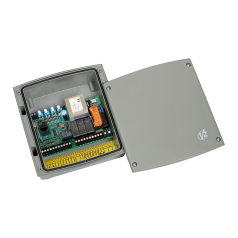
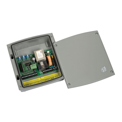
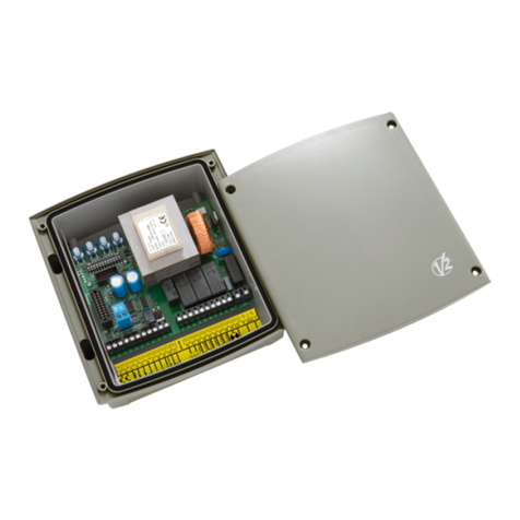
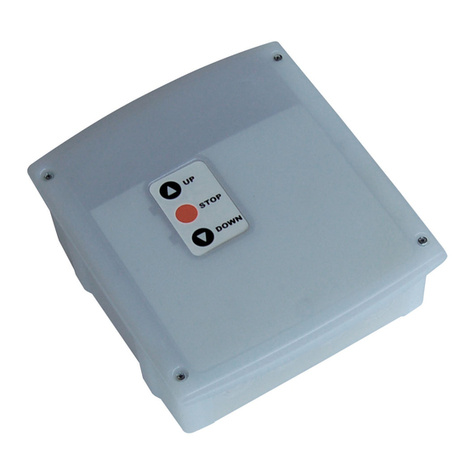
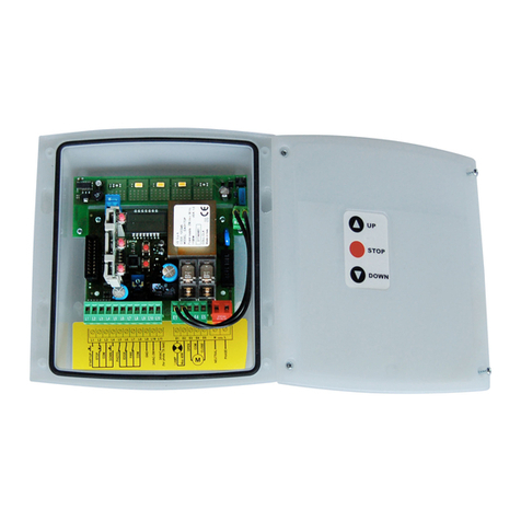
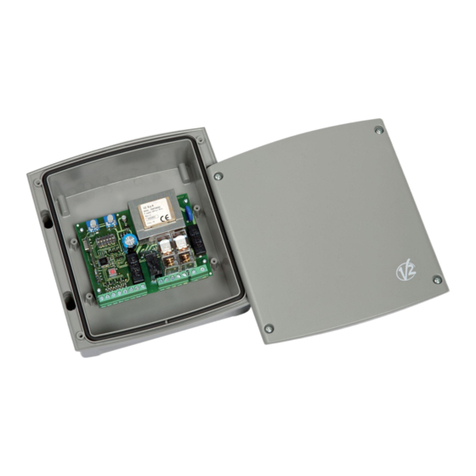
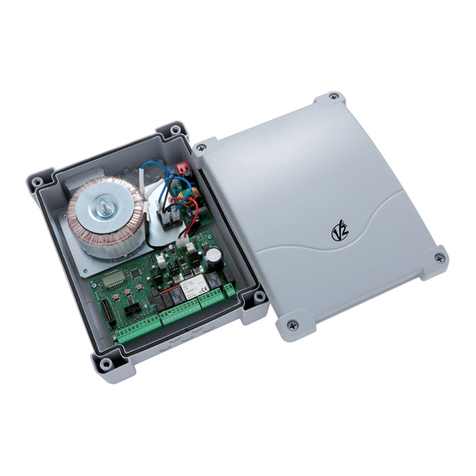
V2 PD9 User manual

PD9
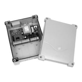
24V DIGITAL CONTROL UNIT FOR SINGLE AND DOUBLE-SWING GATES
I
GB
GATESTORE Ltd
682 Anlaby High Rd
Kingston Upon Hull. HU3 6UZ
tel. 0845 226 3123
fax. 01482 505001
www.vidue.co.uk
COMPANY
WITH QUALITY SYSTEM
CERTIFIED BY QMSI
UNI EN ISO9001
IL n. 155
EDIZ. 05/05/03

15
INDEX
IMPORTANT REMARKS . . . . . . . . . . . . . . . . . . . . . . . . . . . . . . . . . . . . . . . . . . . . . . . . . . . . . . . . . . . . .16
CONFORMITY TO REGULATIONS . . . . . . . . . . . . . . . . . . . . . . . . . . . . . . . . . . . . . . . . . . . . . . . . . . . . . . .16
DESCRIPTION OF THE CONTROL UNIT . . . . . . . . . . . . . . . . . . . . . . . . . . . . . . . . . . . . . . . . . . . . . . . . . . .17
TERMINAL CONNECTIONS . . . . . . . . . . . . . . . . . . . . . . . . . . . . . . . . . . . . . . . . . . . . . . . . . . . . . . . . . . .17
CONTROL PANEL . . . . . . . . . . . . . . . . . . . . . . . . . . . . . . . . . . . . . . . . . . . . . . . . . . . . . . . . . . . . . . . . .18
PROGRAMMING . . . . . . . . . . . . . . . . . . . . . . . . . . . . . . . . . . . . . . . . . . . . . . . . . . . . . . . . . . . . . . . . . .18
FUNCTION OF THE BUTTONS, MENU, UP AND DOWN . . . . . . . . . . . . . . . . . . . . . . . . . . . . . . . . . . . . . . . .18
MOTOR CONTROL FUNCTION . . . . . . . . . . . . . . . . . . . . . . . . . . . . . . . . . . . . . . . . . . . . . . . . . . . . . . . . .19
WARNING LIGHT DESCRIPTION . . . . . . . . . . . . . . . . . . . . . . . . . . . . . . . . . . . . . . . . . . . . . . . . . . . . . . .19
TECHNICAL SPECIFICATIONS . . . . . . . . . . . . . . . . . . . . . . . . . . . . . . . . . . . . . . . . . . . . . . . . . . . . . . . . .19
ACCUMULATOR INSTALLATION . . . . . . . . . . . . . . . . . . . . . . . . . . . . . . . . . . . . . . . . . . . . . . . . . . . . . . . .19
STANDARD PROGRAMMING (DEFAULT) . . . . . . . . . . . . . . . . . . . . . . . . . . . . . . . . . . . . . . . . . . . . . . . . . .20
GATE 1 OPENING TIME . . . . . . . . . . . . . . . . . . . . . . . . . . . . . . . . . . . . . . . . . . . . . . . . . . . . . . . . . . . . .20
GATE 2 OPENING TIME . . . . . . . . . . . . . . . . . . . . . . . . . . . . . . . . . . . . . . . . . . . . . . . . . . . . . . . . . . . . .20
OPENING TIME OF PEDESTRIAN GATE . . . . . . . . . . . . . . . . . . . . . . . . . . . . . . . . . . . . . . . . . . . . . . . . . . .20
CLOSING TIME GATE 1 . . . . . . . . . . . . . . . . . . . . . . . . . . . . . . . . . . . . . . . . . . . . . . . . . . . . . . . . . . . . .20
CLOSING TIME GATE 2 . . . . . . . . . . . . . . . . . . . . . . . . . . . . . . . . . . . . . . . . . . . . . . . . . . . . . . . . . . . . .20
CLOSING OF PEDESTRIAN GATE . . . . . . . . . . . . . . . . . . . . . . . . . . . . . . . . . . . . . . . . . . . . . . . . . . . . . . .20
GATE DELAY DURING OPENING . . . . . . . . . . . . . . . . . . . . . . . . . . . . . . . . . . . . . . . . . . . . . . . . . . . . . . .20
GATE DELAY DURING CLOSING . . . . . . . . . . . . . . . . . . . . . . . . . . . . . . . . . . . . . . . . . . . . . . . . . . . . . . .21
LOCK TIME . . . . . . . . . . . . . . . . . . . . . . . . . . . . . . . . . . . . . . . . . . . . . . . . . . . . . . . . . . . . . . . . . . . . .21
BACKLASH TIME . . . . . . . . . . . . . . . . . . . . . . . . . . . . . . . . . . . . . . . . . . . . . . . . . . . . . . . . . . . . . . . . .21
PRE-FLASHING TIME . . . . . . . . . . . . . . . . . . . . . . . . . . . . . . . . . . . . . . . . . . . . . . . . . . . . . . . . . . . . . . .21
MOTOR POWER 1 . . . . . . . . . . . . . . . . . . . . . . . . . . . . . . . . . . . . . . . . . . . . . . . . . . . . . . . . . . . . . . . .21
MOTOR POWER 2 . . . . . . . . . . . . . . . . . . . . . . . . . . . . . . . . . . . . . . . . . . . . . . . . . . . . . . . . . . . . . . . .21
START SLOWING DOWN . . . . . . . . . . . . . . . . . . . . . . . . . . . . . . . . . . . . . . . . . . . . . . . . . . . . . . . . . . . .21
END OF STROKE SLOWING DOWN . . . . . . . . . . . . . . . . . . . . . . . . . . . . . . . . . . . . . . . . . . . . . . . . . . . . .21
START IN OPENING . . . . . . . . . . . . . . . . . . . . . . . . . . . . . . . . . . . . . . . . . . . . . . . . . . . . . . . . . . . . . . .22
START IN CLOSING . . . . . . . . . . . . . . . . . . . . . . . . . . . . . . . . . . . . . . . . . . . . . . . . . . . . . . . . . . . . . . .22
START IN PAUSE . . . . . . . . . . . . . . . . . . . . . . . . . . . . . . . . . . . . . . . . . . . . . . . . . . . . . . . . . . . . . . . . .22
PEDESTRIAN START IN OPENING . . . . . . . . . . . . . . . . . . . . . . . . . . . . . . . . . . . . . . . . . . . . . . . . . . . . . .22
THE PHOTOCELL IN PAUSE . . . . . . . . . . . . . . . . . . . . . . . . . . . . . . . . . . . . . . . . . . . . . . . . . . . . . . . . . .22
AUTOMATIC CLOSING . . . . . . . . . . . . . . . . . . . . . . . . . . . . . . . . . . . . . . . . . . . . . . . . . . . . . . . . . . . . . .23
COURTESY LIGHTS . . . . . . . . . . . . . . . . . . . . . . . . . . . . . . . . . . . . . . . . . . . . . . . . . . . . . . . . . . . . . . .23
FLASHLIGHT IN PAUSE . . . . . . . . . . . . . . . . . . . . . . . . . . . . . . . . . . . . . . . . . . . . . . . . . . . . . . . . . . . . .23
FLASHLIGHT WITH INTERMITTENCE . . . . . . . . . . . . . . . . . . . . . . . . . . . . . . . . . . . . . . . . . . . . . . . . . . . .24
STOP INPUT . . . . . . . . . . . . . . . . . . . . . . . . . . . . . . . . . . . . . . . . . . . . . . . . . . . . . . . . . . . . . . . . . . . .24
PHOTO 1 INPUT . . . . . . . . . . . . . . . . . . . . . . . . . . . . . . . . . . . . . . . . . . . . . . . . . . . . . . . . . . . . . . . . .24
PHOTO 2 INPUT . . . . . . . . . . . . . . . . . . . . . . . . . . . . . . . . . . . . . . . . . . . . . . . . . . . . . . . . . . . . . . . . .25
COUNTER VIEWING . . . . . . . . . . . . . . . . . . . . . . . . . . . . . . . . . . . . . . . . . . . . . . . . . . . . . . . . . . . . . . .25
END OF PROGRAMMING . . . . . . . . . . . . . . . . . . . . . . . . . . . . . . . . . . . . . . . . . . . . . . . . . . . . . . . . . . . .25
PD9 FUNCTION TABLE . . . . . . . . . . . . . . . . . . . . . . . . . . . . . . . . . . . . . . . . . . . . . . . . . . . . . . . . . . . . .26

16
IMPORTANT REMARKS
For any installation problems please contact
V2 ELETTRONICA TEL. (+39) 01 72 81 24 11
V2 ELETTRONICA has the right to modify the product
without previous notice; it also declines any responsi-
bility to damage or injury to people or things caused
by improper use or wrong installation.
Please read this instruction manual very
carefully before installing and programming
your PD9 control unit.
•This instruction manual is only for qualified
technicians, who specialize in installations and
automations.
•The contents of this instruction manual do not
concern the end user.
•Every programming and/or every maintenance
service should be done only by qualified technicians.
The PD9 control unit can drive one or more
electromechanical actuators for the automation of swing
doors and swing gates. Any other utilization is not in
specification.
AUTOMATION MUST BE IMPLEMENTED IN COMPLIAN-
CE WITH THE EUROPEAN REGULATIONS IN FORCE:
EN 60204–1 (Machinery safety. electrical equipment of
machines, part 1: general rules)
EN 12445 (Safe use of automated locking devices,
test methods)
EN 12453 (Safe use of automated locking devices,
requirements)
•The installer must provide for a device
(es. magnetotermical switch) ensuring the omnipolar
sectioning of the equipment from the power supply.
The standards require a separation of the contacts
of at least 3 mm in each pole (EN 60335-1).
•After making connections on the terminal board,
use one hose clamp to fix dangerous voltage wires
near the terminal board and another hose clamp to
fix safety low voltage wires used for accessories
connection; this way, in case of accidental detach-
ment of a conducting wire, dangerous voltage parts
will not come into contact with safety low voltage
ones.
•The plastic case has an IP55 insulation; to connect
flexible or rigid pipes, use pipefittings having the
same insulation level.
•Installation requires mechanical and electrical skills,
therefore it shall be carried out by qualified personnel
only, who can issue the Compliance Certificate
concerning the whole installation (EEC Machine
Directive 89/392, Annex IIA).
•The automated vehicular gates shall comply with the
following rules: EN 12453, EN 12445, EN 12978
as well as any local rule in force.
•Also the automation upstream electric system shall
comply with the laws and rules in force and be
carried out workmanlike.
•The door thrust force adjustment shall be measured
by means of a proper tool and adjusted according to
the max. limits, which EN 12453 allows.
•We recommend to make use of an emergency
button, to be installed by the automation (connected
to the control unit STOP input) so that the gate may
be immediately stopped in case of danger.
CONFORMITY TO REGULATIONS
V2 ELETTRONICA SPA declares that PD9 is in
conformity with the provisions of the followings
93/68/EEC, 73/23/EEC, and with the standards
referenced here below:
EN 60335–1: Electrical safety
EN 50081–1, EN 50081–2: Electromagnetic compatibility
Racconigi, 10/09/03
V2 ELETTRONICA SPA legal representative
A.Livio Costamagna
DESCRIPTION OF THE CONTROL UNIT
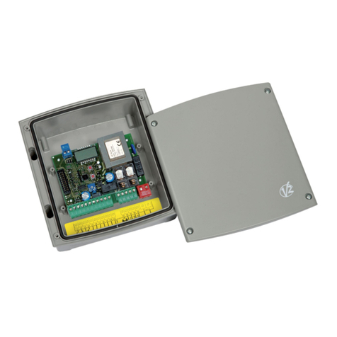
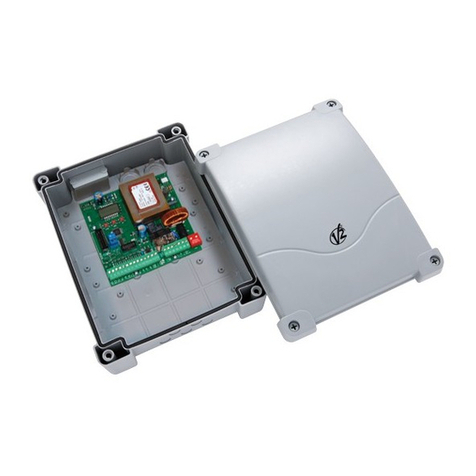
The digital station PD9 is an innovative V2 ELETTRONICA
product that guarantees a safe and reliable automation
of one- and two-shutter gates.
The design of PD9 has been designed to realize a
product that meets all kind of requirements, with a
highly versatile station that satisfies all the necessary
requirements for a functional and efficient installation.
PD9 is provided with a display that, not only makes
programming simple, but also allows a continuous
monitoring of the input statuses; in addition, thanks to
a menu structure, the working schedule and the opera-
tion logic can be set easily.
In compliance with the European standards concerning
electrical safety and electromagnetic compatibility (EN
60335-1, EN 50081-1 and EN 50082-1) it has been
equipped with the low voltage circuit total electric insu-
lation (motors included) from the network voltage.

17
Other characteristics:
•Self-secured power against short circuits inside the
gearcase, on motors and relevant connected
accessories.
•Power adjustment by means of current shutting
(PWM: Power motor controller).
•Obstacle detection by means of monitoring the
motor absorbed current.
•Operation without the network voltage by means of
buffer battery (optional).
•Warning light showing the status of the gate.
•Programmable logic auxiliary relay for courtesy
lights or other use.
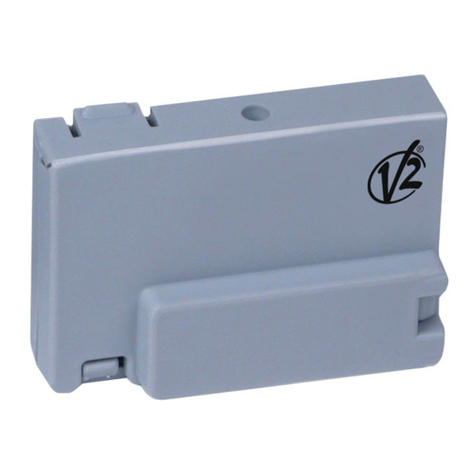
PD9 gearcase has been prearranged for the coupling of
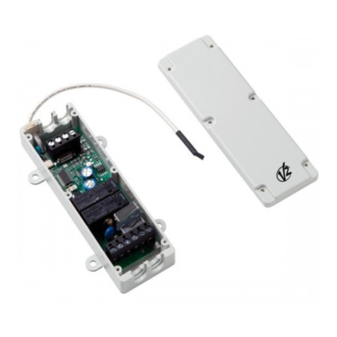
a Personal Pass MR1 receiver having a high-sensitivity
super-heterodyne architecture.
ATTENTION: it is necessary to turn off the
control unit power before doing the operations
mentioned here below. Please pay attention to
the way you connect the removable modules.
PLUGGING THE MR1 RECEIVER
MODULE IN
MR1 module receiver is provided with 4 channels and
each of them is suitable for a command of PD9 control
unit:
CHANNEL 1 START
CHANNEL 2 PEDESTRIAN START
CHANNEL 3 STOP
CHANNEL 4 COURTESY LIGHTS
Before programming 4 channels and function
logics read carefully the instructions of MR1.
WARNING: we suggest to use the external aerial
(model: ANS433) in order to guarantee the maximal
range.
TERMINAL CONNECTION
Antenna
Antenna shield
Opening control for the connec-
tion of control devices with
normally open contact
Opening controls for pedestrian
access for the connection of
control devices with normally
open contact
Common (-)
STOP command
Normally closed contact
Photocell 1
Normally closed contact
Photocell 2
Normally closed contact
Common (-)
Power output +12VDC for photo-
cells and other accessories
Electric lock 12VAC
Warning light 24VAC 3W
Power output 24VDC
for motor 2
Power output 24VDC
for motor 1
Backup battery 12VDC
Courtesy light 230 VAC 10 W
Flashing light 230 VAC 40 W
Neutral 230VAC
Phase 230VAC
1.
2.
3.
4.
5.
6.
7.
8.
9.
10.
11.-12.
13.-14.
15.-16.
17.-18.
19.-20.
21.-22.
23.- 24.
25.
26.
BUTTON P1
LED L1

18
CONTROL PANEL
Perform the electrical connections to the terminal
board, then supply power to the system: the unit will
check the operation status of the display, by turning all
the segments on for 1,5 seconds (8.8.8.8); after this,
the display will show the firmware version for 1,5
seconds, for instance Pr 1.0.
Now, the display will show a control panel:
The control panel represents the physical status of the
terminal board contacts and of the program mode keys:
if the upper vertical segment is on, the contact is clo-
sed; if the lower vertical segment is on, the contact is
open (the above picture shows an instance where the
inputs START, START P, PHOTO1, PHOTO2, and STOP
have all been correctly connected).
PROGRAMMING
The PD9 unit presents a programming structure with
menus, each of which corresponds to a function in the
unit (function menu) or to a working time setting (time
menu).
Time menus allow adjusting the unit working times
(e.g.: leaf opening or closing time, locking time, preflas-
hing time, etc.).
Time programming will be carried out through an algo-
rithm, which speeds up the operations by automatically
matching the adjustment pitch according to the current
set up value:
•from 0 seconds to 1 minute the adjustment pitch is
equal to 0,5 second:
•from 1 minute to 10 minutes the adjustment pitch
is equal to 5 seconds:
•for more than 10 minutes the adjustment pitch is
equal to 30 seconds:
On the other side, the function menu are used to acti-
vate the required functions (e.g. timed lights, PHOTO1
active as a travelling edge, PHOTO2 inactive, etc.).
Some time menus depend on certain function menus
(e.g.: if the AUTOMATIC CLOSING is activated – but only
in this case – a TIME-OUT need to be set); then, to sim-
plify the programming, these time menus have been
placed in the function menus on which they depend.
Specifically, menus AUTOMATIC CLOSING (Ch.AU) and
PHOTOCELL TIME-OUT (Ft.PA) offer some “time menus”
among the selectable options.
FUNCTION OF KEYS
MENU, UP, DOWN
To activate the program mode, proceed as follows.
•After powering the unit, the display should show the
control panel (therefore, check that the connections
made are correct).
•Press and hold key MENU until the display
shows dEF.
Now your programming has been activated.
WARNING: in case no operation is carried out for more
than one minute, the gearcase exits from the program-
ming mode without saving any of your setups and chan-
ges, which will get lost.
You will have to exit from the programming mode –
through the FinE menu – to store all set up data (even
in case you choose the default data).
When the program mode function is activated, press
key UP or DOWN to select the menus, thus performing
a forward or backward shift (for a fast shift, press and
hold).
Press key MENU to access the settings in order to
change them through keys UP and DOWN.
•Pressing the UP key, the menu functions can be
scrolled from below.
•Pressing the DOWN key, the menu functions can be
scrolled from above.
•Pressing the MENU key, the settings to be changed
can be accessed and selected by pressing again.
ATTENTION: when the program mode function is not
activated, pressing of the UP key corresponds to the
START command, pressing of the DOWN key corre-
sponds to the PEDESTRIAN START command: this way,
the service engineer is enabled to perform the test and
the set-up.
The PD9 unit can be set up in two different program
modes: DEFAULT PROGRAM MODE or CUSTOM
PROGRAM MODE.
In the following pages you can find a functions diagram
with information concerning PD9.
For the use of the function chart proceed as follow:
•Press DOWN key to flow the chart from the top to
the bottom. The functions dEF, t.AP1, t.AP2 etc.
will be appear.

19
•Press UP key to flow the chart from the bottom to
the top.
•Press MENU key to flow the chart horizontally; for
example, if the t.ChP function is displayed, by
pressing the MENU key the number 7.0" will be
displayed.
Increase the number pressing UP or DOWN. Press
MENU to display function t.ChP again.
MOTOR CONTROL FUNCTION
At the beginning of the opening cycle, the gearcase
check the motor correct operation. In case one of the
motors fails to operate or it is not correctly connected,
the gate will not open and the display will show you an
“err2” message and the blinking lamp will double blink
for 5 seconds.
WARNING LIGHT DESCRIPTION
The warning light shows in real time the state of the
gate:
STOP light off
IN PAUSE light always on
DURING OPENING the light flashes slowly (2 Hz)
DURING CLOSING the light flashes rapidly (4 Hz)
TECHNICAL SPECIFICATIONS
ACCUMULATOR INSTALLATION
If the antiblackout function is required, a no-maintenan-
ce lead accumulator needs to be connected by means
of special coupling terminals, by strictly complying with
the silk screen printing polarities of the control card.
The accumulator shall have the following characteristics:
TYPE lead and with no maintenance need
VOLTAGE 12 VOLT
CAPACITY 4,2 Ah
Position the battery according to the figure and use the
areas indicated by arrows to install the fairleads. Use
IP55 fairleads or higher.
CAUTION: during functioning with 12V battery, the volta-
ge supplied to motors is smaller than the nominal
value, therefore motors work with low speed and low
thrust. In this situation the current level is not checked,
as the applied forces are not dangerous.
CAUTION: Batteries must be removed before device dis-
posal according to the regulations in force.
Disconnect electric power before any operation.
Power supply 230 VAC 50 / 60 Hz
Max motors load 100 W
Max accessories load 12VDC 10 W
Working temperature -20°C / 60°C
Protection fuse F1 = 5 A
F2 = 400 mA
F3 = 800 mA
Dimensions 295 x 230 x 100 mm
Weight 1200 g
IP protection 55

20
GATE DELAY DURING OPENING
In order to avoid any collision of the gate during the opening
phase, the time of delay should be introduced r.AP, which is
adjustable from 0 to 2 minutes. In such a case the opening
time of gate 2 is delayed in comparison to the gate 1.
This type of programming allows loading the V2 ELETTRONICA
default program in the memory: the standard data that will
be inserted automatically are shown in the table below (in
the column DEFAULT DATA).
Set the wished function pressing the up or DOWN keys and
press MENU key to confirm.
GATE 1 OPENING TIME
This menu is adjustable from 0 to 2 minutes and
determines the time of opening of gate 1.
GATE 2 OPENING TIME
This menu is adjustable from 0 to 2 minutes and
determines the time of opening of gate 2.
WARNING: if it is a one-door gate, such time shall be set up
on 0.
OPENING TIME OF PEDESTRIAN GATE
This menu is adjustable from 0 seconds to t.AP1 and
determines the opening time of pedestrian gate.
CLOSING TIME GATE 1
This menu is adjustable from 0 to 2 minutes which is the
closing time for gate 1. To avoid the uncompleted closing of
the gate, we suggest to set a longer opening time of t.AP1.
CLOSING TIME GATE 2
This menu is adjustable from 0 to 2 minutes which is the
closing time for gate 2. To be sure of the perfect closing of
the gate, we suggest to set a longer opening time t.AP2.
CLOSING OF PEDESTRIAN GATE
This menu is adjustable from 0 to t.Ch1 and determines the
closing time of gate 1. In order to avoid the uncompleted
closing of the gate, we suggest to set a longer opening time
of t.APP.

21
GATE DELAY DURING CLOSING
In order to avoid the colliding of gate's during the closing the
time of delay should de introduced r.Ch, which is adjustable
from 0 to 2 minutes. In such a case the closing time of
gate1 is delayed in comparison to the gate2.
BACKLASH TIME
To avoid that the gate starts the opening phase before the
electrical locks is unhooked, it is possible to introduce a time
of inversion adjustable from 0 to 3 seconds. In this way
during the opening phase, the gate inverts the motion through
the set time permitting the unhooking of the electrical lock.
PRE-FLASHING TIME
This menu permits the introduction of a pre-flashing that
occurs before any movement of the gate either in opening or
in closing phase: the time of pre-flashing can be adjusted
from 0 to 2 minutes.
END OF STROKE SLOWING DOWN
Such a menu allows enabling the door slowing down at their
end of stroke by means of two speeds which can be set up
according to your needs.
vEL1 corresponds to 25% of power.
vEL2 corresponds to 50% of power.
MOTOR 1 POWER
Such a menu enables the sensitivity adjusting of the motor 1
current sensor from 1 to 10.
START SLOWING DOWN
Such a menu enables the motor slowing down start as for
the opening and closing phase.
MOTOR 2 POWER
Such a menu enables the sensitivity adjusting of the motor 1
current sensor from 2 to 10.
LOCK TIME
Before the opening phase starts, the gearcase has to energi-
ze the electrical lock in order to release it and enable the
gate movement. The time t.SEr determines the duration of
excitation, and is adjustable from 0 to 3 seconds. In case
there is no motor lock, set up on no.

22
START IN OPENING
This menu permits to select the functions of start during the
opening phase.
PAUS the command START stop the gate and goes into in
PAUSE.
ChiU the command START close the gate.
no the command START is not available.
START IN CLOSING
This menu permits to select the functions of start during the
closing phase.
StoP the command START stop the gate.
APEr the command START open the gate
START IN PAUSE
This menu permits to select the functions of the command
start during the standstill.
ChiU the command START closes the gate.
no the command START is not available. This function
cannot be selected until the automatic closing has
been activated (menu Ch.AU).
PEDESTRIAN START IN OPENING
This menu permits to select the functions of the command of
START P. during the opening phase.
PAUS the command PEDESTRIAN START stops the gate and
goes in pause.
ChiU the command PEDESTRIAN START closes the gate.
no the command PEDESTRIAN START is not available.
THE PHOTOCELL IN PAUSE
This menu permits to determine the functioning of
two photocells during the pause phase.
rPAU the interruption of the photocell's ray
causes the top of the pause time; when
the photocells work again, the pause time
restart from zero.
t.PCh the interruption of the photocell's ray
causes the top of the pause time; when
the photocells work again, the gate stops
for a time to be set between 0 to 2 min.
If the function is t.PCh, the display shows 5.0: set
the wished functions pressing the UP or DOWN keys.

23
AUTOMATIC CLOSING
Permits the selection between the semiautomatic or automatic functio-
ning. By the semiautomatic functioning the command of START or PEDE-
STRIAN START opens the gate, when the opening is complete the gate
remains still until the successive command of opening, which will reclose
it. On the other hand, it stops automatically and remains in pause phase
for the set time (t.PAU), then it closes again through the set closing time.
no the automatic reclosing is not available, the gate is semiautomatic.
t.PAU the reclosing is available, the standstill time is set from 0 to 999.
IMPORTANT: If the automatic reclosing is not available, is necessary to
enable the start command in pause(menu St.PA)
COURTESY LIGHTS
Thanks to the connection "courtesy light" the
PD9 control unit enables the connection of the
courtesy lights (I.E. garden lights), which can
work automatically (lights on for the whole cycle)
or timed (lights on for a time adjustable from 0 to
999 seconds). The lights turn on with a START or
PEDESTRIAN START control. It is also possible to
control this connection using the code memorized
in the radio input tEL4, in this last case the con-
nection "courtesy light" becomes an auxiliary connection to which it is possible to match one of the
following functional logics:
monostable:it activates the output relay through all the tx transmission time, when the
transmission ends the relay is disconnected.
bistable:it activates the relay with the tx first transmission, the relay disconnects with the
second transmission.
timer:the tx transmission triggers the relay which disconnects automatically after a time
adjustable between 0 and 999 seconds.
t.LUC Courtesy lights switch on when the gate moves and when it stops they stay switched on for
a time which can be set up from 0 to 20 minutes.
CiCL the courtesy lights are on through the whole cycle.
AUS auxiliary exit with adjustable logical functioning.
If the function selected is AUS, one of the following will appear on the display:
tiM timed auxiliary exit (time adjustable from 0 to 999 seconds)
biSt auxiliary output relay with bistable functioning
Mon auxiliary output relay with monostable functioning
FLASHLIGHT IN PAUSE
This menu permits to activate or to disable the flashlight
during the pause time.

24
PHOTO 1 INPUT
This input can be activated for the connection of two diffe-
rent safety devices: the photocell or the rib. The rib (contact
normally closed) is an active safety device in opening and
closing (now active during the backlash): its intervention
during the opening phase stops the gate, inverts the motion
for 4 s, without offsetting the doors. On the other hand, the
intervention of the rib in closing phase stops the gate,
inverts the motion with the offset of the doors. The photocell
1 (contact normally closed) is an active security in opening
and closing: the intervention of the photocell during the clo-
sing stops the gate, at its disengagement the gate inverts
the motion.
Differently the intervention of the photocell in opening stops
the gate, at its disengagement the gate starts opening again.
It is necessary to install the photocell 1 properly, in order to
cover the action space of the gate.
no the opening of PHOTO1 is not available
Cost the opening of PHOTO 1 is available for the connection
of the rib.
APCh the opening of PHOTO 1 is available for the connection
of the photocell
TIMER FUNCTION
This function permits to program the time bands of opening
and closing. It is necessary to connect a 24h timer with a
contact normally open in parallel with the START or PEDE-
STRIAN START input. When the timer contact is closed, the
gate gets into opening phase and remains opened until the
contact of the timer opens causing the re-closing of the gate.
IMPORTANT: for a correct functioning it is necessary to
activate the automatic closing (menu Ch.AU.)
FLASHLIGHT WITH INTERMITTENCE
The control unit PD9 permits the connection of a flashlight
with or without intermittence. If the flashlight is equipped with
an inner intermittence effect, it is necessary to select the
option "Si", but if it has no inner intermittence, it is neces-
sary to select the option "no" in order to make it flash.
STOP INPUT
This menu permits to select the functions associated to the
command of STOP.
no the input STOP is not available
ProS the input STOP stops the gate: pressing the command
START the gate continues the motion
invE the command STOP stops the gate: at the next START
the gate starts moving in the opposite direction.
NOTE: during the pause, the STOP command will stop the
pause time count, the next START command will always close
the gate.

25
PHOTO 2 INPUT
The photocell 2 is active in closing: if it is dimmed during the
closing it stops the gate and inverts the motion. The option CFCh
activates the photocell even when the gate is still: closed gate
means that no impulse has been given, either it is in pause or it has
received a STOP command. In this case through all the time of the
darkening of the photocell the control unit does not receive any com-
mand of activation at any opening / closing cycle.
CFCh the input PHOTO 2 is available: the photocell is active in
closing and also when the gate is still
no the input PHOTO 2 is not available
Ch the input PHOTO 2 is available: the photocell is active
only during the closing
END OF PROGRAMMING
This menu allows to finish the programming (both default and
personalized) saving the modified data into memory.
no further corrections to carry out: do not quit the
programming
Si end of programming
THE INSERTED DATA HAVE BEEN MEMORIZED: THE CONTROL
UNIT IS READY TO BE USED.
COUNTER VIEWING
Such a menu allows viewing the number of opera-
tion cycles which such automatism carries out and
it also enables the final user to set up a limit
value in order to show him when the actuators
service is required.
tot.Total number of completed cycles (the
display views in thousands, press DOWN
to view units).
SErv number of cycles before the next request
for service.
Such a function is disabled by default, by pressing
UP the display will view -01.0, which shows a
1000-cycle countdown after which PD9 will show
the final user that a service is required. Such a
number has been rounded off to hundreds and it
can be set up on 1000-step; set up the desired
value, and then press MENU to confirm.
The request for a service will be signalled by means of double blinks
during the whole operation cycle.
WARNING: only a qualified staff shall carry out all service operations.
Once the service has been carried out, the relevant service menu
SErv shall be set up again.
PD9 will continue signalling the request for a service until such para-
meter is not set up.

26
PD9 FUNCTION TABLE
DISPLAY
dEF.
t.AP1
t.AP2
t.APP
t.Ch1
t.Ch2
t.ChP
r.AP
r.Ch
t.SEr
t.inv
t.PrE
Pot1
Pot2
P.raL
F.rAL
St.AP
St.Ch
St.PA
SP.AP
Ft.PA
DATA
no/Si
0.5" ÷ 2.0'
0.5" ÷ 2.0'
0" ÷ t.AP1
0.5" ÷ 2.0'
0.5" ÷ 2.0'
0" ÷ t.Ch1
0.5"÷ 2.0'
0.5" ÷ 2.0'
0.5" ÷ 3.0"
no
0.5" ÷ 3.0"
no
0.5" ÷ 2.0'
no
1 ÷ 10
1 ÷ 10
no/Si
vEL1
no
vEL2
PAUS
ChiU
no
Stop
APEr
ChiU
no
PAUS
ChiU
no
rPAU
t.PCh
DEFAULT
DATA
no
22.5"
22.5"
6.0"
25"
25"
7.5"
1.0"
3.0"
0.5"
no
1.0"
4
4
Si
vEL1
PAUS
StoP
ChiU
PAUS
r.PAU
MEMO
DATA
DESCRIPTION
Load V2 ELETTRONICA standard data
Gate 1 opening time
Gate 2 opening time
Opening time of pedestrian gate
Gate 1 closing time
Gate 2 closing time
Closing time of pedestrian gate
Gate delay during opening
Gate delay during closing
Electrical lock operation time
-Lock is not energized (it corresponds to 0)
Backlash time
-Disabled recoil (it corresponds to 0)
Pre-flashing time
-Disabled pre-blink (it corresponds to 0)
Under stress motor 1 alarm threshold (it deals with a conventional number)
Under stress motor 2 alarm threshold (it deals with a conventional number)
Start slowing down.
End of stroke slowing down
-Motor slowing down at speed 1.
-Disabled slowing down.
-Motor slowing down at speed 2.
Start in opening
-Stop the gate and goes in pause
-Command close gate
-Start command is not available
Start in closing
-Start command stop the gate
-Start command open the gate
Start in pause
-Start command closes the gate
-Start command is not available
Pedestrian in opening
-Gate goes in pause
-Pedestrian start command closes the gate
-Pedestrian start command is not available
Photocell in pause
-Pause time recharged
-Gate stop for a time to be set between 0 to 120 s

27
DEFAULT
DATA
no
t.LUC=1'
no
no
no
no
no
CFCh
tot.
no
no
PD9 FUNCTION TABLE
DISPLAY
Ch.AU
LUCi
LP.PA
In.LP
OroL
StoP
Fot 1
Fot 2
Cont
Fine
DATA
no
0.5" ÷ 20'
t.LUC
CiCL
AUS
tiM
Mon
biSt
no/Si
no/Si
no/Si
no
ProS
invE
no
CoSt
APCh
CFCh
no
Ch
tot.
Man
no
Si
DESCRIPTION
Automatic closing
-The automatic closing is not active (it corresponds to 0)
-The gate closes after the setup time)
Courtesy Light
-Lights start time adjustable from 0 to 20 min.
-Lights are on trough the whole cycle
-Auxiliary output
-Timed aux out (from 0 to 20 min.)
-Aux out relay with bistable functioning
-Aux out relay with monostable functioning
Flashlight in pause
Flashlight with intermittence
Timer function
STOP input
-STOP input not available
-STOP command stops the gate: pressing the START command gate
continues the motion
-STOP command stops the gate: START command starts moving in
the opposite direction
PHOTO 1 input
-Not available
-Input is available for the connection of the rib
-Input is available for the connection of the photocell
PHOTO 2 input
-Photocell is active in closing and also when the gate is still
-Not available
-Photocell is active during the closing
Counter viewing
-Total number of completed cycles (the display views in thousands
or in units)
-Number of cycles before the next request for service (such a
number has been rounded off to hundreds and it can be set up
on 1000-step; in case it is set up on 0, the request will be
disabled and no will be viewed)
End of programming
-It does not exit from the program menu
-It exits from the program menu by storing the setup parameters
MEMO
DATA

28
NOTE
Table of contents
Other V2 Control Unit manuals