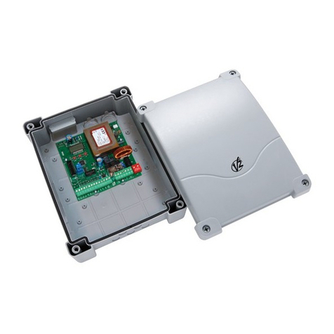
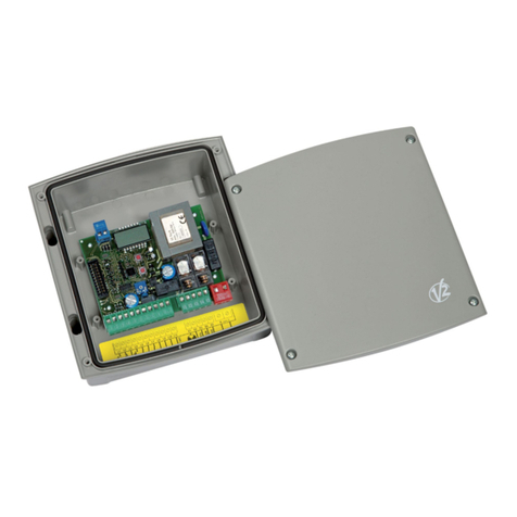
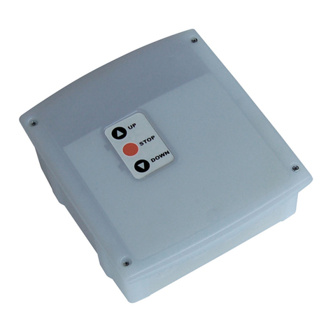
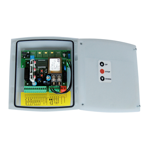
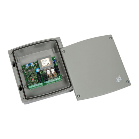
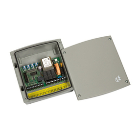
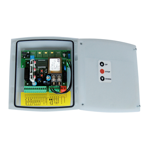
V2 City9 User manual

IL n. 253-1
EDIZ. 08/07/2008
V2 S.p.A.
Corso Principi di Piemonte, 65/67 - 12035 RACCONIGI (CN) ITALY
tel. +39 01 72 81 24 11 fax +39 01 72 84 050
[email protected] www.v2home.com
City9
CENTRA E DI COMANDO ANA OGICA PER
CANCE I SCORREVO I
ANA OGUE CONTRO UNIT FOR S IDING GATES
ARMOIRE DE COMMANDE ANA OGIQUE POUR
PORTAI S COU ISSANTS
CUADRO DE MANIOBRA ANA ÓGICO PARA
PUERTAS CORREDERAS
CENTRA DE COMANDO ANA ÓGICA PARA
PORTÕES CORREDIÇOS
I
GB
F
E
P


I
AVVERTENZE IMPORTANTI ......................................................1
CONFORMITÀ ALLE NORMATIVE..............................................1
DESCRIZIONE DELLA CENTRALE ..............................................1
CARATTERISTIC E TECNIC E ..................................................1
TABELLA COLLEGAMENTI ELETTRICI ........................................2
REGOLAZIONE DELLA POTENZA E DEI TEMPI DI LAVORO ........3
INDICATORI (LED) SULLA CENTRALE ........................................3
MONTAGGIO DEI PASSACAVI ..................................................3
INSTALLAZIONE........................................................................4
PROGRAMMAZIONE DELLA LOGICA DI FUNZIONAMENTO ......6
GB
IMPORTANT REMARKS ............................................................7
DECLARATION OF CONFORMITY..............................................7
DESCRIPTION OF T E CONTROL UNIT......................................7
TEC NICAL SPECIFICATIONS....................................................7
ELECTRICAL CONNECTIONS TABLE ..........................................8
ADJUSTMENT OF T E POWER AND OPERATIONAL TIMES........9
CONTROL UNIT INDICATORS (LEDs) ........................................9
CABLE GLAND ASSEMBLY........................................................9
INSTALLATION ..........................................................................10
PROGRAMMING T E OPERATIONAL LOGIC ............................12
F
CONSEILS IMPORTANTS ..........................................................13
CONFORMITÉ AUX NORMES....................................................13
DESCRIPTION DE L'ARMOIRE DE COMMANDE ........................13
CARACTÉRISTIQUES TEC NIQUES............................................13
TABLEAU BRANC EMENTS ELECTRIQUES ................................14
RÉGLAGE DE LA PUISSANCE ET DES TEMPS DE TRAVAIL ........15
INDICATEURS (DELs) SUR L'ARMOIRE DE COMMANDE ............15
MONTAGE DES PASSE-CÂBLES ..............................................15
INSTALLATION ..........................................................................16
PROGRAMMATION DE LA LOGIQUE DE FONCTIONNEMENT ....18
E
ADVERTENCIAS IMPORTANTES ................................................19
CONFORMIDAD A LAS NORMATIVAS ......................................19
DESCRIPCION DEL CUADRO ....................................................19
CARACTERISTICAS TÉCNICAS..................................................19
CUADRO DE CONEXIONES ELECTRICAS ..................................20
REGULACIÓN DE LA POTENCIA Y DE LOS
TIEMPOS DE TRABAJO ............................................................21
INDICADORES (DIODOS LUMINOSOS) EN LA CENTRALITA ......21
MONTAJE DE LOS PRENSAESTOPAS ........................................21
INSTALACIÓN ..........................................................................22
PROGRAMACIÓN DE LA LÓGICA DE FUNCIONAMIENTO ........24
P
AVISOS IMPORTANTES ............................................................25
DECLARAÇÃO DE CONFORMIDADE ........................................25
DESCRIÇÃO DO QUADRO........................................................25
CARACTERÍSTICAS TÉCNICAS..................................................25
TABELA CONEXÕES ELÉCTRICAS..............................................26
REGULAÇÃO DA POTÊNCIA E DOS TEMPOS DE TRABAL O ....27
INDICADORES (LED) NO QUADRO............................................27
MONTAGEM DOS PASSADORES DE CABOS ............................27
INSTALAÇÃO............................................................................28
PROGRAMAÇÃO DA LÓGICA DE FUNCIONAMENTO ..............30


ITA IANO
1
AVVERTENZE IMPORTANTI
Per chiarimenti tecnici o problemi di installazione contatta il
Servizio Clienti V2 al Numero Verde 800-134908 attivo dal
lunedì al venerdì dalle 8:30 alle 12:30 e dalle 14:00 alle 18:00
V2 S.p.A. si riserva il diritto di apportare eventuali
modifiche al prodotto senza preavviso; inoltre declina ogni
responsabilità per danni a persone o cose dovuti ad un uso
improprio o ad un’errata installazione.
eggere attentamente il seguente manuale di
istruzioni prima di procedere con l'installazione e la
programmazione della centrale di comando.
• Il presente manuale di istruzioni è destinato solamente a
personale tecnico qualificato nel campo delle installazioni di
automazioni.
• Nessuna delle informazioni contenute all'interno del manuale
può essere interessante o utile per l'utilizzatore finale.
• Qualsiasi operazione di manutenzione o di programmazione
deve essere eseguita esclusivamente da personale qualificato.
’AUTOMAZIONE DEVE ESSERE REA IZZATA IN
CONFORMITÀ VIGENTI NORMATIVE EUROPEE:
EN 60204-1 (Sicurezza del macchinario, equipaggiamento
elettrico delle macchine, parte 1: regole generali).
EN 12445 (Sicurezza nell'uso di chiusure automatizzate,
metodi di prova).
EN 12453 (Sicurezza nell'uso di chiusure automatizzate,
requisiti).
• L'installatore deve provvedere all'installazione di un
dispositivo (es. interruttore magnetotermico) che assicuri il
sezionamento onnipolare del sistema dalla rete di
alimentazione. La normativa richiede una separazione dei
contatti di almeno 3 mm in ciascun polo (EN 60335-1).
• Una volta effettuati i collegamenti sulla morsettiera, è
necessario mettere delle fascette rispettivamente sui
conduttori a tensione di rete in prossimità della morsettiera
e sui conduttori per i collegamenti delle parti esterne
(accessori). In tal modo, nel caso di un distacco accidentale
di un conduttore, si evita che le parti a tensione di rete
possano andare in contatto con parti a bassissima tensione
di sicurezza.
• Per la connessione di tubi rigidi e flessibili o passacavi utilizzare
raccordi conformi al grado di protezione IP55 o superiore.
• L’installazione richiede competenze in campo elettrico e
meccanico; deve essere eseguita solamente da personale
qualificato in grado di rilasciare la dichiarazione di conformità
di tipo A sull’installazione completa (Direttiva macchine
89/392 CEE, allegato IIA).
• E’ obbligo attenersi alle seguenti norme per chiusure
veicolari automatizzate: EN 12453, EN 12445, EN 12978
ed alle eventuali prescrizioni nazionali.
• Anche l’impianto elettrico a monte dell’automazione deve
rispondere alle vigenti normative ed essere eseguito a
regola d’arte.
• La regolazione della forza di spinta dell’anta deve essere
misurata con apposito strumento e regolata in accordo ai
valori massimi ammessi dalla normativa EN 12453.
• Collegare il conduttore di terra dei motori all'impianto di
messa a terra della rete di alimentazione.
• Osservare le necessarie precauzioni (esempio bracciale
antistatico) nel maneggiare le parti sensibili alle scariche
elettrostatiche.
DICHIARAZIONE DI CONFORMITÀ
V2 S.p.A. dichiara che i prodotti CITY9 sono conformi ai requisiti
essenziali fissati dalle seguenti direttive:
- 89/336/CEE (Direttiva EMC secondo le norme EN 61000-6-2,
EN 61000-6-3 + EN 50336)
- 2006/95/CEE (Direttiva Bassa Tensione secondo le norme
EN 60335-1 + EN 60335-2-103)
- 99/05/CEE (Direttiva Radio secondo le norme EN 301 489-3)
Racconigi, lì 14/06/2007
Il rappresentante legale della V2 S.p.A.
A.Livio Costamagna
DESCRIZIONE DE A CENTRA E
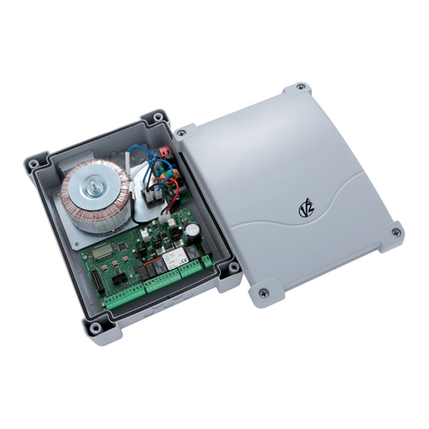
La centrale CITY9 è un innovativo prodotto V2 che garantisce
sicurezza ed affidabilità per l'automazione di cancelli scorrevoli.
La progettazione della CITY9 ha mirato alla realizzazione di un
prodotto che si adatta a tutte le esigenze, ottenendo una
centrale estremamente versatile che soddisfa tutti i requisiti
necessari per un'installazione funzionale ed efficiente.
• Alimentazione 230 VAC o 120 VAC, a seconda dei modelli,
per 1 motore monofase max 700W.
• Ingresso per selettore chiave o pulsante.
• Ingresso per fotocellula di sicurezza.
• Ingresso per costa di sicurezza in grado di gestire coste
classiche con contatto normalmente chiuso e coste a gomma
conduttiva con resistenza nominale 8,2 kohm.
• Ingressi per finecorsa in apertura e chiusura.
• Test dei dispositivi di sicurezza prima di ogni apertura.
• Logica di funzionamento programmabile tramite dip-switch.
• Regolazione potenza motore e tempi di lavoro tramite
trimmer.
• Connettore rapido per l’inserimento di un ricevitore della
serie Mr1.
• Monitoraggio degli ingressi tramite LED.
• Uscita per la luce di cortesia.
• Contenitore IP55.
CARATTERISTICHE
TECNICHE Modelli 230V Modelli 120V
Alimentazione 230V / 50 z 120V / 60 z
Carico max motore 700W 700W
Carico max accessori
alimentati a 24 VAC 3W 3W
Temperatura di lavoro -20 ÷ +60 °C -20 ÷ +60 °C
Fusibili di protezione F1 = 5A delayed F1 = 8A delayed
Dimensioni 170 x 185 x 70 mm
Peso 800 g
Protezione IP55

ITA IANO
2
TABE A CO EGAMENTI E ETTRICI
1 Centrale antenna
2 Schermatura antenna
3 Comando di apertura per il collegamento di
dispositivi tradizionali con contatto N.A.
4 Comando di apertura pedonale per il collegamento
di dispositivi tradizionali con contatto N.A.
5 Comando di STOP. Contatto N.C.
6 Fotocellula. Contatto N.C.
7 Costa. Contatto N.C. o costa a gomma resistiva
8 Comune (-) comandi
9 - 10 Uscita alimentazione 24VAC per fotocellule ed altri
accessori
10 - 11 Alimentazione TX fotocellule per Test funzionale
C1 Apertura motore
C2 Comune motore
C3 Chiusura motore
D1 - D2 Contatto per attivare il temporizzatore di una luce di
cortesia
D3 - D4 Lampeggiante 230V 40W / 120V 40W
NNeutro alimentazione 230V / 120V
Fase alimentazione 230V / 120V
AFinecorsa apertura. Contatto N.C.
BFinecorsa chiusura. Contatto N.C.
CNON UTILIZZATO
DComune (-) finecorsa
J1 NON UTILIZZATO
ATTENZIONE:
Gli ingressi normalmente chiusi (STOP, PHOTO, EDGE) se non sono utilizzati devono essere ponticellati con il comune comandi
COM (-).
Gli ingressi finecorsa apertura FCA (A) e finecorsa chiusura (B) se non sono utilizzati devono essere ponticellati con il comune
finecorsa (D)
J1

ITA IANO
REGO AZIONE DE A POTENZA E DEI TEMPI
DI AVORO
La potenza e i tempi di lavoro sono regolabili tramite 3 trimmer
presenti sulla centrale:
POWER: potenza del motore.
WORK: tempo di lavoro del motore (2 ÷ 120 secondi).
ATTENZIONE: si consiglia di eseguire l'impostazione del
tempo di lavoro con la funzione di rallentamento disabilitata (DIP
5 OFF).
ATTENZIONE: la regolazione dei tempi deve essere
eseguita con il cancello a riposo
PAUSE: tempo di pausa che precede la richiusura
automatica (2 ÷ 150 secondi).
INDICATORI ( ED) SU A CENTRA E
Le caselle evidenziate indicano la condizione dei led quando il
cancello è a riposo.
ED ACCESO SPENTO
START ingresso START chiuso ingresso START aperto
IN2 ingresso START P. chiuso ingresso START P. aperto
STOP ingresso STOP chiuso ingresso STOP aperto
PHOTO ingresso P OTO chiuso ingresso P OTO aperto
EDGE
Costa tradizionale
Ingresso EDGE chiuso
(costa non schiacciata)
Ingresso EDGE aperto
(costa schiacciata)
Costa a gomma resistiva
Ingresso EDGE chiuso
(costa schiacciata) Ingresso EDGE aperto
(anomalia)
Costa NON schiacciata:
8K2 tra ingresso EDGE e
comune (-)
FCA Finecorsa apertura chiuso Finecorsa apertura aperto
FCC Finecorsa chiusura chiuso Finecorsa chiusura aperto
mains Centrale alimentata Centrale NON alimentata
overload Sovraccarico
alimentazione accessori
Alimentazione accessori
nei limiti di funzionamento
MONTAGGIO DEI PASSACAVI
Il contenitore è predisposto per il montaggio di 4
passacavi nelle apposite sedi con prerottura.
Il tipo di passacavi è indicato in figura.
ATTENZIONE:
• Prima di forare il contenitore smontare la
scheda elettronica.
• Forare il contenitore con una fresa adeguata
rispetto alle dimensioni del passacavo.
• Fissare i passacavi con gli apposidi dadi.
3

ITA IANO
4
INSTA AZIONE
L’installazione della centrale, dei dispositivi di sicurezza e degli
accessori deve essere eseguita con l’alimentazione scollegata.
A IMENTAZIONE
La centrale deve essere alimentata da una linea elettrica a
230V - 50 z o 120V - 60 z a seconda dei modelli, protetta con
interruttore magnetotermico differenziale conforme alle
normative di legge.
Collegare i cavi di alimentazione ai morsetti eNdella centrale.
MOTORE
La centrale può pilotare un motore asincrono in corrente
alternata.
Collegare i cavi del motore come segue:
• Cavo per l’apertura al morsetto C1
• Cavo per la chiusura al morsetto C3
• Cavo comune di ritorno al morsetto C2
• Condensatore di spunto tra i morsetti C1 eC3
AMPEGGIATORE
La centrale prevede l’utilizzo di un lampeggiatore a 230V - 40W
o 120V - 40W con intermittenza interna.
Collegare i cavi ai morsetti D3 eD4.
UCE DI CORTESIA
Questa uscita fornisce un contatto pulito normalmente aperto
che si chiude per circa 1 secondo all'inizio di una fase di apertura.
Questo contatto può essere utilizzato per attivare il
temporizzatore di una luce di cortesia (carico max: 230V - 4 A).
NOTA: Se non si dispone di un temporizzatore si può scegliere di
pilotare la luce di cortesia utilizzando il canale 4 del ricevitore
MR1: canale programmabile come bistabile o timer (leggere
attentamente le istruzioni allegate al ricevitore MR1).
Il contatto è fornito sui morsetti D1 eD2.
FOTOCE U E
La centrale fornisce un’alimentazione a 24VAC per fotocellule
con contatto normalmente chiuso e può eseguire un test di
funzionamento prima di iniziare l’apertura del cancello.
Il funzionamento della fotocellula può avere due impostazioni:
1. Fotocellula attiva sempre:
L'intervento della fotocellula durante l'apertura o la chiusura
causa l'arresto del cancello. Al ripristino della fotocellula il
cancello si riaprirà completamente.
2. Fotocellula NON attiva in apertura:
L'intervento della fotocellula durante l’apertura viene ignorato.
L'intervento della fotocellula durante la chiusura causa la
riapertura completa del cancello.
Indipendentemente dall’impostazione scelta, quando il cancello è
aperto in pausa, il conteggio del tempo per l'eventuale richiusura
automatica avrà inizio solo dopo che la fotocellula verrà
ripristinata.
• Collegare i cavi di alimentazione dei trasmettitori delle
fotocellule tra i morsetti 10 (GND) e 11 (+) della centrale.
• Collegare i cavi di alimentazione dei ricevitori delle
fotocellule tra i morsetti 10 (GND) e 9 (+) della centrale.
• Collegare l’uscita dei ricevitori delle fotocellule tra i morsetti
6 e8 della centrale.
COSTE SENSIBI I
La centrale è dotata di un ingresso per gestire le coste di
sicurezza; questo ingresso è in grado di gestire la costa classica
con contatto normalmente chiuso e la costa a gomma conduttiva
con resistenza nominale 8,2 kohm.
Il funzionamento della costa può avere due impostazioni:
1. Costa attiva sempre:
L'intervento della costa durante l'apertura o la chiusura
causa l'inversione del movimento per liberare il corpo che
ha causato l’intervento della costa.
Dopo circa 3 secondi si avrà l’arresto del cancello.
2. Costa NON attiva in apertura:
L'intervento della costa durante l’apertura viene ignorato.
L'intervento della costa durante la chiusura causa la
riapertura completa del cancello.
Indipendentemente dall’impostazione scelta l'eventuale successiva
richiusura automatica verrà annullata.
Costa classica con contatto normalmente chiuso: collegare i
cavi della costa tra i morsetti 7 e8 della centrale.
Per soddisfare i requisiti della normativa EN12978 è necessario
installare coste sensibili dotate di una centralina che ne verifichi
costantemente la corretta funzionalità. Se si utilizzano centraline
che hanno la possibilità di eseguire il test mediante interruzione
dell’alimentazione, collegare i cavi di alimentazione della
centralina tra i morsetti 10 (GND) e 11 (+).

ITA IANO
5
Costa a gomma conduttiva:collegare i cavi della costa tra i
morsetti 7 e8 della centrale.
ATTENZIONE: il test di funzionamento sulle coste è
riservato alle coste ottiche e alle coste tradizionali (solo se
equipaggiate con apposita centralina).
NON abilitare la funzione di test se si utilizzano delle coste
a gomma conduttiva o delle coste tradizionali non
equipaggiate con apposita centralina per il controllo del
funzionamento.
NOTA: per il collegamento di coste ottiche utilizzare
l’apposita interfaccia (codice 35A024) disattivando il test di
funzionamento sulle coste.
INGRESSO DI START
L’ingresso di START è predisposto per il collegamento di dispositivi
con contatto normalmente aperto.
La funzione dipende dalla modalità di funzionamento impostata
sul dip-switch 4.
Modalità passo-passo
Comandi successivi di start provocano nell'ordine:
쩚쩛apertura 쩚쩛stop 쩚쩛chiusura 쩚쩛stop 쩚
Modalità “ad inversione”
Lo Start durante l'apertura provoca la chiusura.
Lo Start durante la chiusura provoca l'apertura.
Lo Start a cancello aperto comanda sempre la chiusura;
l’unico caso in cui questo non si verifica immediatamente è
quando la chiusura automatica è abilitata e lo start in apertura
non è accettato: in questo caso specifico lo start fa ricominciare
da zero il conteggio del tempo di pausa, dopo il quale il cancello
richiuderà.
In entrambe le modalità si può disabilitare il comando di Start
durante l'apertura del cancello agendo sul dip-switch 3.
Collegare i cavi del dispositivo che comanda l’ingresso di start tra
i morsetti 3 e8 della centrale.
START PEDONA E
Lo start pedonale, a cancello chiuso, provoca l’apertura parziale
(circa metà corsa) del cancello. Successivi comandi di start
pedonale funzioneranno secondo la logica passo-passo.
Durante un ciclo pedonale il comando di start provoca l’apertura
completa del cancello.
Collegare i cavi del dispositivo che comanda l’ingresso di start
pedonale tra i morsetti 4 e8 della centrale.
STOP
L'ingresso di STOP è predisposto per dispositivi con contatto
normalmente chiuso.
Il comando di STOP provoca il blocco immediato del cancello.
Il successivo comando di START attiva il cancello nel verso di
marcia opposto.
Se il comando di STOP viene dato durante l'apertura o la pausa,
non ci sarà la successiva richiusura automatica.
Collegare i cavi del dispositivo che comanda l’ingresso di stop tra
i morsetti 5 e8 della centrale.
INGRESSI FINECORSA
La centrale è predisposta per il collegamento di fine corsa con
contatto normalmente chiuso che viene aperto quando il cancello
raggiunge la posizione desiderata.
Collegare i cavi dei finecorsa come segue:
• Fine corsa in apertura tra i morsetti AeD.
• Fine corsa in chiusura tra i morsetti BeD.
RICEVITORE AD INNESTO
La centrale è predisposta per l'innesto di un ricevitore della serie
MR1 con architettura super-eterodina ad elevata sensibilità.
ATTENZIONE: Prima di eseguire le seguenti operazioni
togliere alimentazione alla centrale. Porre la massima
attenzione al verso di innesto dei moduli estraibili.
Il modulo ricevitore MR1 ha a disposizione 4 canali ad ognuno dei
quali è associato un comando della centrale CITY9:
• CANALE 1 쩚쩚쩛쩛START
• CANALE 2 쩚쩚쩛쩛START PEDONALE
• CANALE 3 쩚쩚쩛쩛STOP
• CANALE 4 쩚쩚쩛쩛LUCI DI CORTESIA
ATTENZIONE: Per la programmazione dei 4 canali e delle
logiche di funzionamento leggere attentamente le istruzioni
allegate al ricevitore MR1.
ANTENNA ESTERNA
Si consiglia di utilizzare l'antenna esterna per garantire la
massima portata radio.
Collegare il polo caldo dell’antenna al morsetto 1 della centrale
e la calza al morsetto 2.

ITA IANO
6
PROGRAMMAZIONE DE A OGICA DI FUNZIONAMENTO
È possibile ottenere diverse logiche di funzionamento della centrale agendo semplicemente sui dip-switch presenti sulla scheda. Qui di
seguito sono illustrate le funzioni associate ad ogni singolo dip-switch.
DIP FUNZIONE IMPOSTAZIONE DESCRIZIONE
1Prelampeggio ON Disabilitato Il lampeggiante si accende nel momento in cui il motore viene avviato
OFF Abilitato Il lampeggiante si accende per 2 sec. e poi viene avviato il motore
2Chiusura
automatica
ON Abilitata Il cancello viene chiuso automaticamente dopo il tempo impostato con il
trimmer PAUSE
OFF Disabilitata Il cancello rimane aperto terminata la fase di apertura. Sarà necessario
comandare la chiusura con un altro comando di START
3Start in apertura ON Non accettato Un comando di START durante la fase di apertura non viene sentito
OFF Accettato Un comando di START durante la fase di apertura viene accettato
4Logica di
funzionamento
ON Inversione Lo Start durante l'apertura provoca la chiusura.
Lo Start durante la chiusura provoca l'apertura.
OFF Passo-passo Comandi successivi di start provocano nell'ordine:
apertura 쩚쩛stop 쩚쩛chiusura 쩚쩛stop...
5 Rallentamento
ON Abilitato Al termine di ogni fase di apertura e chiusura il motore rallenta il moto per
evitare chiusure rumorose e rimbalzi.
ATTENZIONE: in caso di cancelli particolarmente pesanti o con forti
attriti, è sconsigliato attivare la funzione di rallentamento perchè
potrebbe provocare arresti indesiderati.
OFF Disabilitato
6 Spunto ON Disabilitato All’inizio di ogni fase di apertura e chiusura il motore viene avviato
al massimo della potenza
OFF Abilitato
7 Antislittamento
ON Disabilitato
Il tempo utilizzato per un’apertura o una chiusura sarà sempre quello impostato
con il trimmer WORK, anche se il movimento precedente è stato interrotto
prima della scadenza di tale tempo.
OFF Abilitato
Quando un’apertura (o chiusura) viene interrotta prima dello scadere del tempo
impostato (ad esempio per intervento di una delle sicurezze o per un comando
di start), la durata della chiusura (o apertura) successiva non sarà quella
impostata con il trimmer WORK, ma sarà pari al tempo effettivamente trascorso,
più un breve tempo aggiuntivo per compensare l’inerzia del cancello in arresto.
8 Fotocellula
ON Attiva sempre L'intervento della fotocellula durante l'apertura o la chiusura causa l'arresto del
cancello. Al ripristino della fotocellula il cancello si riaprirà completamente.
OFF NON attiva in
apertura
L'intervento della fotocellula durante l’apertura viene ignorato. L'intervento della
fotocellula durante la chiusura causa la riapertura completa del cancello.
9 Test fotocellula
ON Abilitato La centrale effettua un test di funzionamento sulle fotocellule prima di avviare
ogni apertura o chiusura. Se le fotocellule non funzionano correttamente il
cancello non entra movimento e si ha un lampeggio di circa 8 secondi.
ATTENZIONE: collegare correttamente il TX della fotocellula
OFF Disabilitato
10 Tipo di costa
di sicurezza
ON Costa a gomma
conduttiva
Selezionare questa opzione se si utilizzano coste a gomma conduttiva con
resistenza nominale 8K2.
OFF Costa tradizionale o
costa ottica
Selezionare questa opzione se si utilizzano coste tradizionali con contatto
normalmente chiuso o coste ottiche.
11 Costa di
sicurezza
ON Attiva sempre
L'intervento della costa durante l'apertura o la chiusura causa l'inversione del
movimento per liberare il corpo che ha causato l’intervento della costa.
Dopo circa 3 secondi si avrà l’arresto del cancello.
OFF NON attiva in
apertura
L'intervento della costa durante l’apertura viene ignorato. L'intervento della costa
durante la chiusura causa la riapertura completa del cancello.
12 Test costa di
sicurezza
ON Abilitato La centrale effettua un test di funzionamento sulle coste prima di avviare ogni
apertura o chiusura. Se le coste non funzionano correttamente il cancello non
entra movimento e si ha un lampeggio di circa 8 secondi.
NON abilitare la funzione di test se si utilizzano delle coste a gomma
conduttiva o delle coste tradizionali non equipaggiate con apposita
centralina per il controllo del funzionamento.
OFF Disabilitato

ENG ISH
7
IMPORTANT REMARKS
For any installation problem please contact our Customer Service
at the number +39-0172.812411 operating Monday to Friday
from 8:30 to 12:30 and from 14:00 to 18:00.
V2 has the right to modify the product without previous
notice; it also declines any responsibility to damage or
injury to people or things caused by improper use or
wrong installation.
Please read this instruction manual very carefully
before installing and programming your control unit.
• This instruction manual is only for qualified technicians,
who specialize in installations and automations.
• The contents of this instruction manual do not concern the
end user.
• Every programming and/or every maintenance service
should be done only by qualified technicians.
AUTOMATION MUST BE IMP EMENTED IN COMP IANCE
WITH THE EUROPEAN REGU ATIONS IN FORCE:
EN 60204-1 (Machinery safety. electrical equipment of
machines, part 1: general rules)
EN 12445 (Safe use of automated locking devices,
test methods)
EN 12453 (Safe use of automated locking devices,
requirements)
• The installer must provide for a device (es. magnetotermical
switch) ensuring the omnipolar sectioning of the equipment
from the power supply.
The standards require a separation of the contacts
of at least 3 mm in each pole (EN 60335-1).
• After making connections on the terminal board, use one
hose clamp to fix dangerous voltage wires near the terminal
board and another hose clamp to fix safety low voltage wires
used for accessories connection; this way, in case of
accidental detachment of a conducting wire, dangerous
voltage parts will not come into contact with safety low
voltage ones.
• The plastic case has an IP55 insulation; to connect flexible
or rigid pipes, use pipefittings having the same insulation
level.
• Installation requires mechanical and electrical skills,
therefore it shall be carried out by qualified personnel only,
who can issue the Compliance Certificate concerning the
whole installation (EEC Machine Directive 89/392, Annex IIA).
• The automated vehicular gates shall comply with the
following rules: EN 12453, EN 12445, EN 12978 as well
as any local rule in force.
• Also the automation upstream electric system shall comply
with the laws and rules in force and be carried out
workmanlike.
• The door thrust force adjustment shall be measured
by means of a proper tool and adjusted according to
the max. limits, which EN 12453 allows.
• Connect the earthing lead of the motors to the electricity
grid earth system.
• Observe all necessary precautions (e.g. anti-static bracelet)
for handling parts sensitive to electrostatic discharges.
DEC ARATION OF CONFORMITY
V2 S.p.A. hereby declare that CITY9 products conform to the
essential requirements established in the following directives:
- 89/336/CEE (EMC Directive in accordance with standards
EN 61000-6-2, EN 61000-6-3 + EN 50336)
- 2006/95/CEE (Low Voltage Directive in accordance with
standards EN 60335-1 + EN 60335-2-103)
- 99/05/CEE (Radio Directive in accordance with standard
EN 301 489-3)
Racconigi, lì 14/06/2007
V2 S.p.A. legal representative.
A.Livio Costamagna
DESCRIPTION OF THE CONTRO UNIT
The CITY9 control unit is an innovative V2 product guaranteeing
safety and reliability for sliding gate automation.
The CITY9 design has been aimed at creating a product which
adapts to suit all needs, thus obtaining an extremely versatile
control unit satisfying all the necessary requirements for a
functional and efficient installation.
• 230V - 50 z or 120V - 60 z power supplies, depending on
the model, for 1 x 700 W max. single phase motor.
• Input for keyswitch or push-button.
• Input for safety photocell.
• Input for safety edge, capable of handling standard edges
with switch normally closed, optical edges and conductive
rubber edges with nominal resistance of 8.2 kOhms.
• Inputs for open and close limit switches.
• Pre-opening safety device testing.
• Dip-switch programmable operational logic.
• Adjustment of motor power and operation time by means of
a trimmer.
• Quick plug-in connector for inserting a Mr1 series receiver.
• LED monitoring of inputs.
• Courtesy light output.
• IP55 casing.
TECHNICA
SPECIFICATIONS 230V models 120V models
Power supply 230V / 50 z 120V / 60 z
Max motor load 700W 700W
Max accessories load 24V 3W 3W
Working temperature -20 ÷ +60 °C -20 ÷ +60 °C
Protection fuse F1 = 5A delayed F1 = 8A delayed
Dimensions 170 x 185 x 70 mm
Weight 800 g
Protection IP55

ENG ISH
EECTRICA CONNECTION TAB E
1 Antenna
2 Antenna shield
3 Opening command for a standard connection device
with switch normally open.
4 Pedestrian opening command for a standard
connection device with switch normally open.
5 STOP command. N.C. switch
6 Photocell. N.C. switch
7 Edge. Switch N.C. or resistive rubber edge
8 Commands common (-) line
9 - 10 24 VAC power output for photocells and other
accessories
10 - 11 Power supply for functional test TX photocell
C1 Motor open
C2 Motor common
C3 Motor close
D1 - D2 Courtesy light timer activation switch
D3 - D4 230V - 40W / 120V - 40W blinker
N230V / 120V power supply - neutral
230V / 120V power supply - phase
ALimit switch open. N.C. switch
BLimit switch closed. N.C. switch
CNOT USED
DLimit switch common (-) line
J1 NOT USED
P EASE NOTE: If not used, the normally closed inputs (STOP, PHOTO, EDGE) must be jumpered with the commands
common line COM (-)
If not used, the open limit switch FCA (A) and close limit switch FCC (B) inputs must be jumpered with the limit switch
common line (D)
J1
8

ENG ISH
CONTRO UNIT INDICATORS ( EDS)
The highlighted boxes indicate the state of the LEDs when the
gate is resting.
CAB E G AND ASSEMB Y
The casing can accept 4 cable glands in the special
easy-break housings.
The type of cable gland is indicated in the figure.
P EASE NOTE:
• Remove the electronic circuit board before drill
the casing.
• Drill the container using a suitably sized cutter,
according to the dimensions of the cable gland.
• Fix the cable glands using the special nuts.
ED ON OFF
START START input closed START input open
IN2 START P. input closed START P. input open
STOP STOP input closed STOP input open
PHOTO P OTO input closed P OTO input open
EDGE
Standard edge
EDGE input closed (edge
not pressed)
EDGE input open (edge
pressed)
Resistive rubber edge
EDGE input closed
(edge pressed) EDGE input open
(fault)
Edge NO pressed: 8K2
between EDGE input and
common (-)
FCA Opening limit switch closed Opening limit switch open
FCC Closing limit switch closed Closing limit switch open
mains Control unit powered-up Control unit NOT powered-up
overload Accessory power supply
overload
Accessory power supply within
normal operational limits
9
ADJUSTMENT OF THE POWER AND
OPERATIONA TIMES
The power and operating times may be adjusted by means of 3
trimmers located on the control unit:
POWER: motor power.
WORK: motor operating time (2 - 120 seconds).
P EASE NOTE: it is recommended that operating times be
set with the slow down function disabled (DIP 5 OFF).
WARNING: the adjustment of times has to be made
when the gate is still
PAUSE: pause time before automatic re-closure
(2 - 150 seconds).

ENG ISH
10
INSTA ATION
Installation of the control unit, the safety devices and accessories
must be performed with the power supply disconnected.
POWER SUPP Y
The control unit must be powered by means of a 230 V - 50 z
or 120 V - 60 z power line, depending on the model, protected
by a differential magnetothermal switch in compliance with legal
regulations.
Connect the power cables to the control unit and Nterminals.
MOTOR
The control unit can control one asynchronous AC motor.
Connect the cables for motor as follows:
• Opening cable to terminal C1
• Closing cable to terminal C3
• Common return cable to terminal C2
• Start-up capacitor between terminals C1 and C3
B INKER
The control unit provides for the use of a 230 V - 40 W or 120 V
- 40 W blinker with built-in intermittence.
Connect the cables to terminals D3 and D4.
COURTESY IGHT
This output has a normally-open clean contact relay which closes
for approx. 1 second at the start of an opening phase. This
switch may be used to activate a courtesy light timer (max. load:
230V - 4A).
P EASE NOTE: If there is no timer, the courtesy light can be
controlled using channel 4 of receiver MR1: bistable or timer
programmable channel (read the instructions for the receiver MR1
thoroughly).
The switch is on terminals D1 and D2.
PHOTOCE S
The control unit has a 24VAC power supply for photocells with
switch normally closed, and can perform an operational test
before starting the gate opening procedure.
The photocell can be used with two settings:
1. Photocell always active:
Intervention of the photocell during opening or closing
causes the gate to stop.
When the photocell restores, the gate re-opens completely.
2. Photocell NOT active during opening:
Intervention of the photocell during opening is ignored.
Intervention of the photocell during closing causes the gate
to re-open completely.
Independently of the setting selected, when the gate is paused
while opening, the time count for any automatic re-closure will
only start after the photocell restores.
• Connect the photocell transmitter power cables between
terminals 10 (GND) and 11 (+) on the control unit.
• Connect the photocell receiver power cables between
terminals 10 (GND) and 9 (+) on the control unit.
• Connect the photocell receiver output between terminals 6
and 8 on the control unit.
SAFETY EDGES
The control unit has an input for controlling safety edges; this
input is capable of controlling standard edges with switch
normally closed and conductive rubber edges with nominal
resistance of 8.2 kOhms.
Edges can be used with two settings:
1. Edge always active:
Intervention of the edge during opening or closing causes
inversion of the direction of movement in order to free the
body that caused the edge to intervene.
The gate stops after approx. 3 seconds.
2. Edge NOT active during opening:
Intervention of the edge during opening is ignored.
Intervention of the edge during closing causes the gate
re-open completely.
Independently of the settings selected, any subsequent automatic
re-closure will be cancelled.
Standard edge with switch normally closed: connect the
edge cables between terminals 7 and 8 on the control unit.
In order to satisfy the requirements of standard EN12978, it is
necessary to install safety edges with a control unit which
constantly monitors correct operation. If control units are used
with the option of running tests by means of interrupting the
power supply, connect the control unit power supply cables
between terminals 10 (GND) and 11 (+).

ENG ISH
11
Conductive rubber edge: connect the edge cables between
terminals 7 and 8 on the control unit.
P EASE NOTE: operational testing on edges is reserved for
optical edges and standard edges (only if equipped with suitable
control units).
DO NOT enable testing if conductive rubber edges are used
or standard edges used without a suitable control unit for
controlling function.
NOTE: use the special interface (code 35A024) for
connection of the optical bars, de-activating the operational test
on the bars.
START INPUT
The START input is preset for connecting devices with the switch
normally open. Function depends on the mode of operation set
by means of dip-switch 4.
Step mode
Subsequent start commands cause, in order:
쩚쩛opening 쩚쩛stop 쩚쩛closure 쩚쩛stop 쩚
“Inversion” mode
Start during opening causes closure.
Start during closure causes opening.
Start with the gate open always results in closure;
The only case where this does not occur immediately is when
automatic closure is enabled and start while opening is not
accepted: in this specific case, start makes the pause time count
start from zero, after which the gate will be re-closed.
In both modes it is possible to disable the Start command during
gate opening by means of dip-switch 3.
Connect the start input control device cables between terminals
3 and 8 on the control unit.
PEDESTRIAN START
With the gate closed, the pedestrian start causes partial opening
(approx. half way) of the gate. Subsequent pedestrian start
commands will function according to step logic.
During a pedestrian cycle, the start command causes the
complete opening of the gate.
Connect the start input control device cables between terminals
4 and 8 on the control unit.
STOP
The STOP input is intended for devices with the switch normally
closed.
The STOP command causes the immediate stop of the gate.
A subsequent START command activates the gate in the opposite
direction of movement.
If the STOP command is given during opening or pause, then
there will be no subsequent automatic re-closure.
Connect the stop input control device cables between terminals
5 and 8 on the control unit.
IMIT SWITCH INPUTS
The control unit is configured for connecting a switch with switch
normally closed, which is opened when the gate reaches the
desired position.
Connect the limit switch cables as follows:
• Closing limit switch between terminals Aand D.
• Opening limit switch between terminals Band D.
P UG-IN RECEIVER
The control unit is suitable for plugging-in an MR1 series receiver
with high sensitivity super-heterodyne architecture.
P EASE NOTE: Disconnect the power to the control unit
before performing the following operations. Pay the utmost
attention to the direction of insertion of plug-in modules.
The MR1 receiver module has 4 channels, each with an
associated command on the CITY9 control unit:
• C ANNEL 1 쩚쩚쩛쩛START
• C ANNEL 2 쩚쩚쩛쩛PEDESTRIAN START
• C ANNEL 3 쩚쩚쩛쩛STOP
• C ANNEL 4 쩚쩚쩛쩛COURTESY LIG TS
P EASE NOTE:
Read the instructions supplied with the MR1 receiver thoroughly for
details on programming the 4 channels and the operational logic.
EXTERNA ANTENNA
It is recommended the external antenna be used in order to
guarantee maximum radio capacity.
Connect the antenna hot pole to terminal 1 of the control unit
and the braiding to terminal 2.

ENG ISH
12
PROGRAMMING THE OPERATIONA OGIC
It is possible for the control unit to use several different operational logic states, by simply moving the dip-switches located on the card.
The functions associated with each individual dip-switch are listed below.
DIP FUNCTION SETTING DESCRIPTION
1 Pre-flashing ON Disabled The blinker is switched on when the motor is started
OFF Enabled The blinker is switched on 2 seconds before the motor is started
2Automatic
closure
ON Enabled The gate is closed automatically after the period of time set by the PAUSE
trimmer
OFF Disabled On completion of the opening step, the gate remains open. It is necessary to
instruct closure with another START command
3 Start opening ON Not accepted Any START command issued during opening is not heard
OFF Accepted Any START command issued during opening is accepted
4 Operational logic
ON Inversion Start during opening causes closure.
Start during closure causes opening.
OFF Step Commands subsequent to starting cause, in order:
open 쩚쩛stop 쩚쩛close 쩚쩛stop...
5 Slow down
ON Enabled At the end of each opening and closing step, the motor slows down in order to
avoid noisy closure and bouncing.
WARNING: With gates that are particularly heavy, or with high friction,
breaking is not recommended, as it may lead to undesired stopping
OFF Disabled
6 Start off ON Disabled At the start of each opening and closing step, the motor is started at maximum
power
OFF Enabled
7 Anti-slip
ON Disabled
The time used for opening or closure will always be the value set by the WORK
trimmer, even if the previous operation has been interrupted before the expiry
of such time.
OFF Enabled
When an opening (or closing) operation is interrupted before expiry of the set
time (for example due to the intervention of one of the safety devices or due to
a start command), the duration of the subsequent closing (or opening)
operation will not be that set by the WORK trimmer, but will be equal to the
time effectively elapsed, plus a short supplemental time in order to compensate
for the inertia of the gate.
8 Photocell
ON Always active Intervention of the photocell during opening or closing causes the gate to stop.
When the photocell restores, the gate re-opens completely.
OFF NOT active during
opening:
Intervention of the photocell during opening is ignored. Intervention of the
photocell during closing causes the gate to be re-opened completely.
9 Photocell test
ON Enabled The control unit performs a photocell operational test before starting each
opening or closing operation. If the photocells are not operating correctly, the
gate does not begin to move and the light flashes for approx. 8 seconds.
P EASE NOTE: connect the photocell TX correctly
OFF Disabled
10 Safety edge
type
ON Conductive rubber
edge
Select this option if using conductive rubber edges with nominal resistance of
8K2.
OFF Standard or optical
edge
Select this option if using standard edges with switch normally closed or optical
edges.
11 Safety edge
ON Always active
Intervention of the edge during opening or closing causes inversion of the
direction of movement in order to free the body that caused the edge to
intervene. The gate will be stopped after approx. 3 seconds.
OFF NOT active during
opening:
Intervention of the edge during opening is ignored. Intervention of the edge
during closing causes the gate to re-open completely.
12 Safety edge test
ON Enabled The control unit performs an operational test on the edges before starting each
opening or closing operation. If the edges are not operating correctly, the gate
does not begin to move and the light flashes for approx. 8 seconds.
DO NOT enable testing if conductive rubber edges are used or standard
edges are used without a suitable control unit for controlling function.
OFF Disabled

FRANÇAIS
13
CONSEI S IMPORTANTS
Pour tout précision technique ou problème d’installation
V2 dispose d’un Service Clients à Votre disposition du lundi au
vendredi de 8:30 à 12:30 et de 14:00 heures à 18:00 heures. au
numéro +39-0172.812411
V2 S.p.A. se réserve le droit d’apporter d’éventuelles
modifications au produit sans préavis; elle décline en outre
toute responsabilité pour tous types de dommages aux
personnes ou aux choses dus à une utilisation imporopre
ou à une mauvaise installation.
Avant de proceder avec l'installation et la
programmation, lire attentivement les notices.
•Ce manuel d'instruction est destiné à des techniciens
qualifiés dans le domain des automatismes.
• Aucune des informations contenues dans ce livret pourra
être utile pour le particulier.
• Tous operations de maintenance ou programation doivent
être faites à travers de techniciens qualifiés.
’AUTOMATION DOIT ÊTRE RÉA ISÉE CONFORMÉMENT
AUX DISPOSITIFS NORMATIFS EUROPÉENS EN VIGUEUR
EN 60204-1 (Sécurité de la machinerie. Équipement
électriquedes machines, partie 1: régles
générales).
EN 12445 (Sécurité dans l’utilisation de fermetures
automatisées, méthodes d'essai).
EN 12453 (Sécurité dans l'utilisation de fermetures
automatisées, conditions requises).
• L'installateur doit pourvoir à l'installation d'un dispositif (ex.
interrupteur magnétothermique) qui assure la coupure
omnipolaire de l'équipement du réseau d'alimentation.
La norme requiert une séparation des contacts d'au moins
3 mm pour chaque pôle (EN 60335-1).
• Quand on a effectué les branchements à la borniere, il faut
mettre des bandes sur les conducteurs à tension qui se
trouvent en proximité de la borniere et sur les conducteurs
pour le branchement des parties externes (accessoires).
De cette maniere, en cas de détachement d'un conducteur,
on évite que les partie en tension puissent aller en contact
avec les parties à faible tension de sécurité.
• Pour la connexion de tubes rigides ou flexibles utiliser des
raccordements possédant le IP55 niveau de protection.
• L’installation requiert des compétences en matière
d’électricité et mécaniques; doit être faite exclusivement par
techniciens qualifiés en mesure de délivrer l’attestation de
conformité pour l’installation (Directive 89/392 CEE, - IIA).
• Il est obligatoire se conformer aux normes suivantes pour
fermetures véhiculaires automatisées: EN 12453,
EN 12445, EN 12978 et à toutes éventuelles prescriptions
nationales.
• Même l’installation électrique ou on branche l’automatisme
doit répondre aux normesen vigueur et être fait à règles de
l’art.
• La régulation de la force de poussée du vantail doit être
mesurée avec outil spécial et réglée selon les valeurs maxi
admis par la norme EN 12453.
• Brancher le câble de terre des moteurs à l'installation de
mise à la terre du réseau d'alimentation.
• Précautions nécessaires à prendre (par exemple brassard
antistatique) pour manipuler les parties sensibles aux
décharges électrostatiques.
DÉC ARATION DE CONFORMITÉ
V2 S.p.A. déclare que les produits CITY9 sont conforment aux
qualités requises essentielles fixées par les directives suivantes :
-89/336/CEE (Directive EMC suivant les normes
EN 61000-6-2, EN 61000-6-3 + EN 50336)
- 2006/95/CEE (Directive Basse tension suivant les normes
EN 60335-1 + EN 60335-2-103)
-99/05/CEE (Directive Radio suivant les normes
EN 301 489-3)
Racconigi, lì 14/06/2007
Le représentant dûment habilité V2 S.p.A.
A.Livio Costamagna
DESCRIPTION DE 'ARMOIRE DE
COMMANDE
L'armoire de commande CITY9 est un produit innovant V2, qui
garantit sécurité et fiabilité pour l'automation de portails
coulissants.
La conception de projet de la CITY9 a visé à la réalisation d'un
produit qui soit en mesure de correspondre à toutes les
exigences, parvenant à une armoire avec une grande souplesse
d'utilisation et qui satisfait à toutes les conditions requises
nécessaires pour une installation fonctionnelle et performante.
• Alimentation 230V ou 120V, selon les modèles, pour
1 moteur monophasé max. 700W
• Entrée pour sélecteur à clé ou bouton-poussoir.
• Entrée pour photocellule de sécurité.
• Entrée pour barre palpeuse en mesure de gérer soit les
barres palpeuses classique avec contact normalement
fermé et les barres palpeuses en caoutchouc conducteur avec
résistance nominale 8,2 kOhms.
• Entrées pour fin de course en ouverture et en fermeture.
• Tests des dispositifs de sécurité avant chaque ouverture.
• Logique de fonctionnement programmable par dip-switch.
• Réglage puissance des moteur et temps de travail par
trimmer.
• Connecteur rapide pour l'insertion d'un récepteur série Mr1.
• Monitoring des entrées par DEL.
• Sortie pour la lumière de courtoisie.
• Boîtier IP55.
CARACTÉRISTIQUES
TECHNIQUES Modèles 230V Modèles 120V
Alimentation 230V / 50 z 120V / 60 z
Charge max moteur 700W 700W
Charge max accessoires
24V 3W 3W
Température de travail -20 ÷ +60 °C -20 ÷ +60 °C
Fusible de protection F1 = 5A delayed F1 = 8A delayed
Dimensions 170 x 185 x 70 mm
Poids 800 g
Protection IP55
FRANÇAIS
14
TAB EAU BRANCHEMENTS É ECTRIQUES
C1 Ouverture moteur
C2 Commun moteur
C3 Fermeture moteur
D1 - D2 Contact pour activer le temporisateur d'une lumière
de courtoisie
D3 - D4 Clignotant 230V 40W / 120V 40W
NNeutre alimentation 230V / 120V
Phase alimentation 230V / 120V
AFin de course ouverture. Contact N.F.
BFin de course fermeture. Contact N.F.
CNON UTILISÉ
DCommun (-) fin de course
J1 NON UTILISÉ
ATTENTION: es entrées normalement fermées (STOP, PHOTO, EDGE) si non utilisées doivent être shuntées avec le
commun commandes COM (-)
es entrées fin de course ouverture FCA (A) et fin de course fermeture FCC (B) si non utilisées doivent être shuntées avec le
commun fin de corse (D)
J1
1 Centrale antenne
2 Blindage antenne
3 Commande d'ouverture pour le branchement de
dispositifs traditionnels avec contact N.O.
4 Commande d'ouverture piéton pour le branchement
de dispositifs traditionnels avec contact N.O
5 Commande d'arrêt STOP. Contact N.F.
6 Photocellule. Contact N.F.
7 Barre palpeuse. Contact N.F. ou barre palpeuse en
caoutchouc conducteur résistif
8 Commun (-) commandes
9 - 10 Sortie alimentation 24 VAC pour photocellules et
d'autres accessoires
10 - 11 Alimentation TX photo. pour test de fonctionnement

FRANÇAIS
RÉG AGE DE A PUISSANCE ET DES TEMPS
DE TRAVAI
La puissance et les temps de travail sont réglables par 3 trimmers
se trouvant sur l'armoire de commande:
POWER: puissance du moteur.
WORK: temps de travail des moteurs (2 ÷ 120 secondes).
ATTENTION: il est conseillé d'exécuter la configuration du
temps de travail avec la fonction de ralentissement désactivée
(DIP 5 OFF).
ATTENTION: le réglage des temps doit être effectué
quand le portail est arrêté
PAUSE: temps de pause qui précède le refermeture
automatique (2 ÷ 150 secondes).
MONTAGE DES PASSE-CÂB ES
Le boîtier est conçu pour le montage de 4 passe-
câbles dans leurs propres logements avec système
autocassable.
Le type de passe-câbles est indiqué dans la figure.
ATTENTION:
• Avant de percer le boîtier, démonter la carte
électronique.
• Percer le boîtier avec une fraise adéquate par
rapport aux dimensions du passe-câble.
• Fixer les passe-câbles avec les écrous prévus à
cet effet.
INDICATEURS (DE s) SUR 'ARMOIRE DE
COMMANDE
Les cases mises en évidence indiquent la condition des DELs
quand le portail est en état de repos.
DE AUMÉE ÉTEINTE
START entrée START fermée entrée START ouverte
IN2 entrée START P. fermée entrée START P. ouverte
STOP entrée STOP fermée entrée STOP ouverte
PHOTO entrée P OTO fermée entrée P OTO ouverte
EDGE
Barre palpeuse traditionnelle
Entrée EDGE fermée (barre
palpeuse non écrasée)
Entrée EDGE ouverte
(barre palpeuse écrasée)
Barre palpeuse en caoutchouc conducteur résistif
Entrée EDGE fermée (barre
palpeuse écrasée) Entrée EDGE ouverte
(anomalie)
Barre palpeuse NON
écrasée: 8K2 entre entrée
EDGE et commun (-)
FCA Fin course ouverture fermé Fin course ouverture ouvert
FCC Fin course fermeture fermé Fin course fermeture ouvert
mains Armoire de commande
alimentée
Armoire de commande
NON alimentée
overload Surcharge alimentation
accessoires
Alimentation accessoires
dans les limites de
fonctionnement
15

FRANÇAIS
16
INSTA ATION
L'installation de l'armoire de commande, des dispositifs de
sécurité et des accessoires doit être effectuée avec l'alimentation
débranchée.
A IMENTATION
L'armoire de commande doit être alimentée en 230V - 50 z ou
120V - 60 z selon les modèles, protégée avec interrupteur
magnétothermique différentiel conforme aux normes de loi en
vigueur.
Brancher les câbles d'alimentation aux borniers et Nde
l'armoire de commande.
MOTEUR
L'armoire de commande peut piloter un moteur asynchrone en
courant alternée.
Brancher les câbles du moteur 1 de façon suivante:
• Câble pour l'ouverture à la borne C1
• Câble pour la fermeture à la borne C3
• Câble commun de retour à la borne C2
• Condensateur de démarrage entre les bornes C1 et C3
C IGNOTANT
L'armoire de commande prévoit l'emploi d'un clignotant à 230V -
40W ou 120V - 40W avec intermittence interne.
Brancher les câbles aux bornes D3 et D4.
UMIÈRE DE COURTOISIE
Cette sortie fournit un contact propre normalement ouvert qui se
ferme environ pendant 1 seconde au début d'une phase
d'ouverture. Ce contact peut être utilisé pour activer le tempori-
sateur d'une lumière de courtoisie (charge max.: 230V - 4 A).
REMARQUE: Si l'on ne dispose pas d'un temporisateur on peut
choisir de piloter la lumière de courtoisie en utilisant le canal 4 du
récepteur MR1: canal programmable comme bistable ou minuteur
(lire attentivement les instructions annexées au récepteur MR1).
Le contact est fourni sur les bornes D1 et D2.
PHOTOCE U ES
L'armoire de commande fournit une alimentation à 24VAC pour
les photocellules avec contact normalement fermé et il peut
exécuter un test de fonctionnement avant de commencer
l'ouverture du portail.
Le fonctionnement de la photocellule peut avoir deux configurations:
1. Photocellule active toujours:
L'intervention de la photocellule pendant l'ouverture ou la
fermeture cause l'arrêt du portail. Au rétablissement de la
photocellule le portail s'ouvrira complètement.
2. Photocellule NON active en ouverture:
L'intervention de la photocellule pendant l'ouverture est
ignorée. L'intervention de la photocellule pendant la
fermeture cause la réouverture complète du portail.
Indépendamment de la configuration choisie, quand le portail est
ouvert en état de pause, le comptage du temps pour l'éventuelle
refermeture automatique commencera seulement après le
rétablissement de la photocellule.
• Brancher les câbles d'alimentation des émetteurs des
photocellules entre les bornes 10 (GND) et 11 (+) de
l'armoire de commande.
• Brancher les câbles d'alimentation des récepteurs des
photocellules entre les bornes 10 (GND) et 9 (+) de
l'armoire de commande.
• Brancher la sortie des récepteurs des photocellules entre
les bornes 6 et 8 de l'armoire de commande.
BARRES PA PEUSES
L'armoire de commande est équipée d'une entrée pour gérer les
barres palpeuses de sécurité; Cette entrée est en mesure de gérer
soit la barre palpeuse classique avec contact normalement fermé,
la barre palpeuse optique et la barre palpeuse en caoutchouc
conducteur avec résistance nominale 8,2 kOhms.
Le fonctionnement de la barre palpeuse peut avoir deux
configurations:
1. Barre palpeuse active toujours:
L'intervention de la barre palpeuse pendant l'ouverture ou la
fermeture cause l'inversion du mouvement pour libérer le
corps qui a causé l'intervention de la barre palpeuse.
Après environ 3 secondes on obtiendra l'arrêt du portail.
2. Barre palpeuse NON active en ouverture:
L'intervention de la barre palpeuse pendant l'ouverture est
ignorée. L'intervention de la barre palpeuse pendant la
fermeture cause la réouverture complète du portail.
Indépendamment de la configuration choisie l'éventuelle
refermeture automatique successive sera annulée.
Barre palpeuse classique avec contact normalement fermé:
brancher les câbles de la barre palpeuse entre les bornes 7 et 8
de l'armoire de commande.
Pour satisfaire les qualités requises de la norme EN12978 il est
nécessaire d'installer des barres palpeuses sensibles équipées
d'une centrale qui en vérifie constamment la correcte
fonctionnalité. Si l'on utilise des centrales qui ont la possibilité
d'exécuter le test par coupure de l'alimentation, relier les câbles
d'alimentation de la centrale entre les bornes 10 (GND) et 11 (+).
Other manuals for City9
1
This manual suits for next models
1
Table of contents
Languages:
Other V2 Control Unit manuals
Popular Control Unit manuals by other brands

Honeywell
Honeywell Silent Knight SK-Monitor Installation and maintenance instructions

Pickering
Pickering 40-565A user manual

Bardiani Valvole
Bardiani Valvole BBZO BBZOG instruction manual

Stahl
Stahl 9172 Series operating instructions

MG
MG R6D-SS2 instruction manual

urmet domus
urmet domus DIGIVOICE K-Steel 1038/16 Guide