manuals.online logo
Brands
  1. Home
  2. •
  3. Brands
  4. •
  5. VistaLab
  6. •
  7. Laboratory Equipment
  8. •
  9. VistaLab Ovation M Operating and safety instructions

VistaLab Ovation M Operating and safety instructions

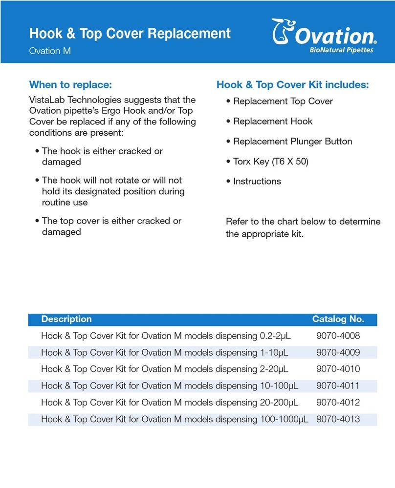
When to replace:
VistaLab echnologies recommends that
the Ovation pipette’s plunger seal be
replaced if any of the following
symptoms are present:
• Damage from caustic vapors
• Build up of dried liquids aspirated
into pipette
• Seal leaks caused by damage to
cylinder
• Liquid leaks out of tip
• Liquid is observed inside air tube or
cylinder
Pl nger Seal Kit incl des:
• 5/64’’ Allen Key
• Replacement Cylinder
• Replacement Plunger Seal
• Replacement Air ube Connector
Cap
• Energizing O-Ring
• Instructions
Refer to the chart below to determine
the appropriate kit.
Description Catalog No.
Plunger eal Kit for Ovation M models dispensing 0.2-2µL 9070-1001
Plunger eal Kit for Ovation M models dispensing 1-10µL 9070-1002
Plunger eal Kit for Ovation M models dispensing 2-20µL 9070-1003
Plunger eal Kit for Ovation M models dispensing 10-100µL 9070-1004
Plunger eal Kit for Ovation M models dispensing 20-200µL 9070-2005
Plunger eal Kit for Ovation M models dispensing 100-1000µL 9070-3006
*
Pl nger Seal Replacement
Ovation M
Replacing a Pl nger Seal:
1. Loosen the two captive screws from
the bottom surface of the pipette
base, using a 5/64’’ Allen Key, until you
can lift the base from the body.
(see Figure 1)
2. Remove the air tube from the rubber
air tube connector cap on the bottom
of the cylinder by gently pulling it from
the circular hole. (see Figure 2)
3. To remove the cylinder, push the
cylinder inwards and rotate it
counterclockwise until the tabs on the
cylinder align with the open slots of the
clear gearbox shell . (see Figure 3)
4.
Remove the plunger seal on the bottom
of the metal plunger by first pushing
down on the plunger button to expose
more of the metal shaft. Then remove
the plunger seal by sliding it off
(see Figure 4). (Note: If the seal remains
stuck to the cylinder top, pop it loose
with a tooth pick or fingernail. Avoid
scratching the plunger with metal tools)
5. Replace the existing plunger seal with
the new plunger seal. Push down on
the plunger button to expose more of
the metal plunger. Then fit the inner
circle of the seal onto the metal
plunger and slide it on until it reaches
the base of the gearbox (see Figure 5)
Figure 1: Screws on base connecting to body
Figure 2: Air tube inserted into connector cap on
botto of cylinder
Figure 3: Unlocked cylinder with tabs in the
open slots
6. Gently release the plunger button and
place the new cylinder provided such
that the tabs on the cylinder align with
the open slot in the clear gearbox
(see Figure 3).
7. Push the cylinder inwards and rotate it
clockwise so that the tabs on the
cylinder sit locked atop the inside of
the clear gearbox (see Figure 6).
8. Place the new rubber air tube
connector cap over the small end of
the cylinder and push down so that
the connector cap is seated firmly on
the cylinder (see Figure 7 on back).
9. lide the new O-Ring over the air tube
connector cap so that it sits firmly over
the base of the connector cap
(see Figures 8 and 9 on back).
10. Reinsert the air tube by pushing the
exposed end into the circular opening
on the air tube connector cap (see
Figure 2). (Note: You may need to
rotate the connector cap to allow the
air tube to reach the circular
opening.You will feel two small
“bumps” when pushing the air tube in
to indicate that it has been fully
inserted. You should be able to feel the
back inside wall of the connector cap if
you push any further. )
Figure 4: Plunger seal on etal plunger shaft
Figure 5: Properly seated plunger seal
Figure 6: Locked cylinder with tabs seated on shell
L070-0006-001 Rev A
VistaLab Technologies, Inc.
2 Geneva Road
Brewster, NY 10509 USA
(914) 244-6226 • (888) 652-6520
11. Verify that you have correctly inserted
the air tube into the connector cap by
using the pipette. Confirm that no
leaks occur and that the pipette is
functioning normally.
12. Fit the base to the body so that it fits
neatly onto the front and back cover
and that the screws fit into the holes.
Use the 5/64’’ Allen Key to tighten the
screws until snug and the two halves
are connected. DO NOT over tighten
the screws ( ee Figure 1).
13. Verify pipette performance.
Figure 7: Air tube connector cap seated on
botto of cylinder
Figure 10: O-Ring incorrectly seated
Figure 8: Sliding O-Ring on Figure 9: O-Ring seated
on connector cap

Other manuals for Ovation M

3

Other VistaLab Laboratory Equipment manuals
VistaLab Ovation QS Manual

VistaLab

VistaLab Ovation QS Manual

VistaLab ali-Q 2 Installation instructions

VistaLab

VistaLab ali-Q 2 Installation instructions

VistaLab Ovation 9060-5009 Guide

VistaLab

VistaLab Ovation 9060-5009 Guide

VistaLab Ovation 9057-2009 Use and care manual

VistaLab

VistaLab Ovation 9057-2009 Use and care manual

VistaLab ali-Q User manual

VistaLab

VistaLab ali-Q User manual

VistaLab Ovation ESC User manual

VistaLab

VistaLab Ovation ESC User manual

VistaLab Ovation M Use and care manual

VistaLab

VistaLab Ovation M Use and care manual

VistaLab MLA Micro D-Tipper Series User manual

VistaLab

VistaLab MLA Micro D-Tipper Series User manual

VistaLab Ovation M Use and care manual

VistaLab

VistaLab Ovation M Use and care manual

VistaLab 1136 Manual

VistaLab

VistaLab 1136 Manual

VistaLab MLA pipette MLA 1061 Manual

VistaLab

VistaLab MLA pipette MLA 1061 Manual

VistaLab Ovation Manual

VistaLab

VistaLab Ovation Manual

VistaLab Ovation 9060-1011 Guide

VistaLab

VistaLab Ovation 9060-1011 Guide
VistaLab Ovation 9060-4005 Guide

VistaLab

VistaLab Ovation 9060-4005 Guide

VistaLab 1070-0002 User manual

VistaLab

VistaLab 1070-0002 User manual
VistaLab Ovation M User manual

VistaLab

VistaLab Ovation M User manual

VistaLab MLA Series User manual

VistaLab

VistaLab MLA Series User manual
Popular Laboratory Equipment manuals by other brands

TESTING 1.0330 operating manual

TESTING

TESTING 1.0330 operating manual

Fresenius Vial OPTIMA PT Operator's guide

Fresenius Vial

Fresenius Vial OPTIMA PT Operator's guide

Diatron Abacus 5 Operator's manual

Diatron

Diatron Abacus 5 Operator's manual

PASCO OS-9255A instruction manual

PASCO

PASCO OS-9255A instruction manual

Tobii Pro Fusion user manual

Tobii Pro

Tobii Pro Fusion user manual

Ivoclar Vivadent IvoBase Series operating instructions

Ivoclar Vivadent

Ivoclar Vivadent IvoBase Series operating instructions

Biobase BFG Series user manual

Biobase

Biobase BFG Series user manual

Hanna Instruments HI83325 instruction manual

Hanna Instruments

Hanna Instruments HI83325 instruction manual

Bruker NanoScope OMV-UNIVERSAL quick start guide

Bruker

Bruker NanoScope OMV-UNIVERSAL quick start guide

Pincore The CoKey Instructions & user's manual

Pincore

Pincore The CoKey Instructions & user's manual

Plasmapp Sterlink FPS-15s Plus user manual

Plasmapp

Plasmapp Sterlink FPS-15s Plus user manual

Agilent Technologies Truevolt Series Operating and service guide

Agilent Technologies

Agilent Technologies Truevolt Series Operating and service guide

Terragene BIONOVA MiniBio manual

Terragene

Terragene BIONOVA MiniBio manual

Rohde & Schwarz R&S OSP Series user manual

Rohde & Schwarz

Rohde & Schwarz R&S OSP Series user manual

MELAG Vacuklav 24 B+ Technical manual

MELAG

MELAG Vacuklav 24 B+ Technical manual

cytiva Amersham ImageQuant 500 operating instructions

cytiva

cytiva Amersham ImageQuant 500 operating instructions

Haag-Streit LI 900 Instructions for use

Haag-Streit

Haag-Streit LI 900 Instructions for use

Baileigh AFS-1600 Operator's manual

Baileigh

Baileigh AFS-1600 Operator's manual

manuals.online logo
manuals.online logoBrands
  • About & Mission
  • Contact us
  • Privacy Policy
  • Terms and Conditions

Copyright 2025 Manuals.Online. All Rights Reserved.