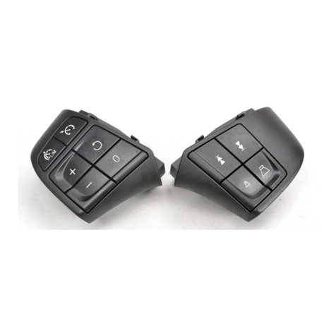
Volvo Link System Reference manual

Service Bulletin
Volvo Trucks North America, Inc.
Greensboro, NC USA
Date Group No. Page
3.2002 397 001 1(32)
Trucks
Volvo Link System
Design and Troubleshooting
Satellite Communication System
W3004840
Volvo Link ECU
The Volvo Link System provides satellite communications between a driver and fleet. It
includes the Volvo Link ECU, GPS antenna, cable, and wiring harnesses. Some vehi-
cles also include a dash switch. This system allows communications between Volvo’s
Web based (fleet) software and the vehicle.
This information includes design and troubleshooting of the vehicle portion of the sys-
tem. For repair procedures, see service procedures in group 397. For fleet software
troubleshooting, see the software help file.
This information contains:
•
“System Operation” page 3
•
“Simplified Schematic” page 12
•
“System Definitions” page 13
•
“MID 142 Satellite Communication” page 14
PV776-TSP156441 USA10063

Page 2
Tools
Special Tools
See the special tool information in group 08 for ordering
instructions.
J-39200
Fluke Multimeter J-43234
30-pin Breakout Harness 9998551 with J-43340
60-pin Breakout Box with Overlay

Volvo Trucks North America, Inc. Date Group No. Page
Service Bulletin 3.2002 397 001 3(32)
Design and Function
System Operation
The Volvo Link System provides satellite communications between the driver and his
fleet home base. The hardware/software that is installed on the vehicle is discussed in
this bulletin. In order for the fleet home base to utilize the system, it must subscribe to
a web based service through Volvo. For information on the web based application and
subscription service, see the Volvo web site at
www.volvotrucks.us.com and look under the “Services”category.
The Volvo Link ECU is programmed differently for Cummins and Volvo engines. At the
time of the original installation in the vehicle, the Volvo Link ECU acquires the Vehicle
Identification Number (VIN) of the vehicle in which it is installed. Replacement of the
ECU with one from another vehicle will not work. System checks within the ECU soft-
ware will recognize that the ECU is not in the proper vehicle and generate a notification
message. The Volvo Link ECU is connected to the J1587/1708 Information Data Link.
Incoming and outgoing messages are read on the instrument cluster graphic display
screen. Messages are sent and received through the vehicle’s radio antenna system.
The vehicle location is identified through a Global Positioning System (GPS) antenna
located in the passenger side mirror head. The ORBCOMM network of Low-Earth Orbit
satellites relays information between the vehicle and fleet.
Some vehicles may be equipped with a “Volvo Action Service”switch that, when acti-
vated, will send a message to Volvo requesting assistance and providing the vehicle
location.

Page 4
System Diagram
W3004841
Volvo Link System
AMultiplex Whip Antennas
BRAMI Antenna Multiplexer box
CGPS Antenna
D* Volvo Action Service Dash Switch
E* Switch Illumination
FRadio
*Switch is not available in all vehicles.

Volvo Trucks North America, Inc. Date Group No. Page
Service Bulletin 3.2002 397 001 5(32)
Sending and Receiving Messages
The system has the ability to send brief text messages
to and from the vehicle, similar to an e-mail system. It
uses the vehicle’s graphic display in the instrument clus-
ter for viewing and entering the messages.
The controls for the graphic display are the 4 buttons in
the stalk switch on the right side of the steering column.
1“Esc”(Escape) is used to return to the previous
menu and cancel a setting/operation.
2“↵”or “SELECT”confirms a highlighted selection of
a menu or character.
3“Up arrow”moves the cursor up and is used when
setting alpha-numeric values.
4“Down arrow”moves the cursor down and is used
when setting alpha-numeric values.
For more information on using the graphic display con-
trols, see the Operator’s Manual, or service information
on “Instrumentation”in group 38.
T3008810
Using the Graphic Display
1 The Volvo Link menu should be the first item shown
in the graphic display. Use the up/down buttons to
highlight it.
2 Press ↵to select Volvo Link.
3 After selecting Volvo Link, another screen will pop
up, offering the choice to send or read messages.
4 For instructions on sending and receiving mes-
sages, see the following:
•“Sending Messages from the Vehicle”page 8
•“Incoming Message Notification from Fleet”
page 6
•“Quick Response to Incoming Messages”page
7
•“Viewing Messages”page 7.
VOLVO LINK
"
GAUGES
FUEL ECONOMY
TIME/DIST
#
Read Messages
Send Messages

Page 6
Incoming Message Notification from Fleet
Messages are received at the vehicle from the fleet operator. When a message is re-
ceived by the Volvo Link ECU, the driver will be notified with the INFO lamp and a
message in the instrument cluster’s graphic display. The message will appear one of
the two following ways:
New Message in Volvo Link
or
Priority Message in Volvo Link
If in a driving situation where it is safe to do so, the driver can press the Esc button
when he/she sees the message.
Pressing the Esc button turns off the INFO lamp.
The driver can read the “New Message”the next time he stops the vehicle. Or the
driver can read a “Priority Message”while driving, provided the vehicle speed is below
55 mph.

Volvo Trucks North America, Inc. Date Group No. Page
Service Bulletin 3.2002 397 001 7(32)
Viewing Messages
To view all stored messages, select “Volvo Link,”then “Read Messages”in the cluster’s
graphic display.
The messages will display, one at a time, with the most recent message shown first.
Once the newest message is displayed, the driver can use the Up/Down buttons to
scroll through the other messages.
Up goes to the next (newer) message. If the newest message is being displayed, the
Up button wraps back to the oldest message.
Down goes to the previous (older) message. If the oldest message is being displayed,
the Down button wraps back to the newest message.
The message buffer will hold 5 messages. If the buffer is full and a new message is re-
ceived, the oldest message will be deleted.
While the vehicle is moving, the last message received is the only one that can be dis-
played, and only if it is a “Priority Message.”
If the driver has access or priority to see the message while driving, the message is
displayed. If not, the driver will see a message directing him to:
Stop Vehicle to Read Message
Quick Response to Incoming Messages
The driver has the option of a Quick Response to the most recent message in the
queue.
The quick response can be sent while driving.
From the message display screen, press ↵to access the Quick Response menu.
The Quick Response uses pre-defined text:
Yes/OK
No
Respond @ Next Stop

Page 8
Sending Messages from the Vehicle
The driver of the vehicle can send messages from the vehicle to the fleet. Messages
can be sent when the vehicle is stopped, but not while it is moving. If you attempt to
send a message when the vehicle is moving, an error message will display, and the
message will not be sent.
The driver can send 3 types of messages, as shown below. These options are se-
lectable from the graphic display.
•Defined Text
•Breakdown
•Free Text
The Defined and Breakdown message lists have approximately 10 message options
within each menu.
Defined Text messages:
Load picked up
Load delivered
Late: less than 1 h
Late: more than 1 h
Company defined 1
Company defined 2
Company defined 3
Company defined 4
Company defined 5
Breakdown messages:
This allows the driver to send breakdown messages along with the vehicle’s GPS loca-
tion back to his fleet, which can then help the driver by sending a service vehicle to his
location.
Towing needed
Tractor tire
Tractor electrical
Tractor air supply
Tractor drive train
Tractor others
Trailer tire
Trailer electrical
Trailer air supply
Trailer axles
Trailer others

Volvo Trucks North America, Inc. Date Group No. Page
Service Bulletin 3.2002 397 001 9(32)
Free Text:
Free text messages are sent as follows:
Select Free Text in the graphic display.
From the blank screen with a cursor, use the up/down arrows to scroll through the
numbers 0–9 and the alphabet to create your message, one character at a time.
Note: using the up arrow, you will scroll through 0–9, then A-Z. Using the down ar-
row, the order is reversed, and you will see Z-A, then 9–0.
For the first character, scroll up or down until you reach the letter/number desired,
then press the ↵button. Repeat for each character.
When finished with the message, press the ↵button and hold for 3 seconds to
send.
Note: if you make a mistake, press Esc to go back to the previous character. To
cancel sending a typed message, press Esc until the message is cleared from the
screen.
After a Message is Sent
After a message is sent, one of the following confirmations will appear on screen:
Message Sent
Sending Not Allowed
No Subscription
Message Sent confirms that the message was sent by the ECU.
If Sending Not Allowed shows on screen, the message was not sent. The reason for
this failure may be that the system is busy. Wait briefly and try sending the message
again. It may also be an indication that the Volvo Link ECU has been placed in the
wrong vehicle (see “Cannot Send or Receive Messages, but No Fault Code”page 31
for more information).
No Subscription indicates that messaging capabilities have been disabled by the fleet.
If Operation Failed appears on screen during an attempt to send a message, this is
either an indication of network congestion, or a system failure. See “MID 142 Satellite
Communication”page 14 for more information.

Page 10
Vehicle Log Data
Total miles, Total Idle Fuel used, Total Fuel used, Total Engine Idle hours, Total Engine
hours, Vehicle Location (GPS).
This data can be requested by the Web or can be set up in the Volvo Link ECU to be
sent at predetermined time intervals.
Data is recorded using the J1587/1708 data link on the vehicle.

Volvo Trucks North America, Inc. Date Group No. Page
Service Bulletin 3.2002 397 001 11(32)
ECU Pinout
W3004839
Volvo Link ECU
Pin Name Description
1 BATT+ Battery Supply (+)
2 BATT- Battery Supply (-)
4 OUTPUT1 Volvo Action Service Dash Switch Illumination (not available
in all vehicles)
14 J1587/1708+ J1587/1708 Data Link +
15 INPUT1 (PWR) Ignition Supply (+)
19 INPUT5 (GND) Volvo Action Service Dash Switch (not available in all vehi-
cles)
30 J1587/1708- J1587/1708 Data Link -
NOTE: Pins 3, 5–13, 16–18 and 20–29 are not used.

Page 12
Simplified Schematic
W3005010
Volvo Link ECU, Simplified Electrical Schematic
1 Powerpoint connector in TEC center (B2–1)
2 Powerpoint connector in TEC center (B1–1)
3 Diagnostic option connector 2, behind TEC center
4 Diagnostic option connector 1, behind TEC center
5 *Switch illumination connector 1
6 *Switch illumination connector 2
“ECU”is the Volvo Link ECU
*“SW”is the Volvo Action Service dash switch, which is not available in all vehicles.
Note: This simplified schematic should be used only to clarify the design features of the Volvo Link system. For
detailed, vehicle-specific schematics, see the “VN/VHD Electrical Schematics”in Group 37.

Volvo Trucks North America, Inc. Date Group No. Page
Service Bulletin 3.2002 397 001 13(32)
System Definitions
Data link An electrical connection for
communication with other
microprocessor-based de-
vices (such as powertrain
control, trip recorders and
maintenance systems) that
are compatible with the ATA
and SAE standard.
GPS Global Positioning System: a
system that uses satellites to
provide users with GPS loca-
tion anywhere in the world.
ORBCOMM Satellite communications
provider used for Volvo Link
system. Part of the Volvo Link
ECU may be referred to as
the ORBCOMM module, be-
cause it is the module
containing the satellite com-
munications circuitry.
PSID PSID is a Volvo Proprietary
SID, or System Identifier. Note
that PSID’s will only show a
numeric value in the graphic
display –no text description.
Volvo Link Volvo Link System. A satellite
communciation system inte-
grated into Volvo vehicles. It
includes the Volvo Link ECU,
GPS antenna and wiring har-
nesses. This system allows
communications between the
fleet (via Volvo’s Web based
software) and the vehicle.
Web World Wide Web or Internet.
Web Application General definition is software
on the Internet, but in this
case, it refers to the Volvo
Link software, usually admin-
istered at a fleet’s home base.

Page 14
Troubleshooting
MID 142 Satellite Communication
ForFault Based troubleshooting, see:
•
“Fault Code Troubleshooting”page 15
ForSymptom Based troubleshooting, see:
•
“Troubleshooting the Messages Shown in the Graphic Display”page 29
•
“Cannot Send or ReceiveMessages,but No Fault Code”page 31
•
“No Response from Vehicle”page 31
•
“Antenna Checks”page 32

Volvo Trucks North America, Inc. Date Group No. Page
Service Bulletin 3.2002 397 001 15(32)
Fault Code Troubleshooting
The system has several failure conditions that can be detected by the ECU. Some of
these conditions could be loss of data link and signals, output failures and GPS failures.
The fault codes can be read by using the instrument cluster graphic display or VCADS
Pro.
NOTE: About Inactive Faults: Low Counts - If the count of an inactive fault is low or
only one, then this may indicate a possible system glitch that may not need any correc-
tive action.
High Counts - If the count of an inactive fault is high, this may indicate a problem in
concerned or related components and wiring/connectors.
Do not automatically replace any component until it has been verified to be bad.
Clear the fault and do the recommended checks as if the fault was active. Also, if pos-
sible, try to recreate the fault by placing the vehicle or component in similar conditions
that may have originally caused the fault. This will help in determining why the fault
was initially logged and also in finding a solution.
NOTE: The descriptions in the table below are the FMI descriptions according to SAE
standards. The text actually shown in the graphic display or in VCADS Pro may vary
slightly.
Fault Code: PIDs Function FMI Check
MID 142 - PID 84 Road Speed 9=data not received/abnormal
update rate Speed sensor or data link fail-
ure. See “Engine Faults”page
18.
MID 142 - PID 89 PTO Status 9=data not received/abnormal
update rate Indicates a problem in the en-
gine system. See “Engine
Faults”page 18.
3=voltage shorted high
4=voltage shorted low
MID 142 - PID 155 Output 1-4
5=current low or open circuit
See “MID 142 PID 154 or 155
Auxiliary Input and Output Sta-
tus”page 20.
MID 142 - PID 155 Input 1-4 12=bad component See “MID 142 PID 154 or 155
Auxiliary Input and Output Sta-
tus”page 20.
MID 142 - PID 154 Input 5-8 12=bad component See “MID 142 PID 154 or 155
Auxiliary Input and Output Sta-
tus”page 20.
MID 142 - PID 183 Fuel Rate 9=data not received/abnormal
update rate Indicates a problem in the en-
gine system. See “Engine
Faults”page 18.
MID 142 - PID 190 Engine Speed 9=data not received/abnormal
update rate Indicates a problem in the en-
gine system. See “Engine
Faults”page 18.
MID 142 - PID 235 Idle Engine Hours 9=data not received/abnormal
update rate Indicates a problem in the en-
gine system. See “Engine
Faults”page 18.
MID 142 - PID 236 Idle Fuel Used 9=data not received/abnormal
update rate Indicates a problem in the en-
gine system. See “Engine
Faults”page 18.
MID 142 - PID 237 External VIN Missing 9=data not received/abnormal
update rate See “MID 142 PID 237 FMI 9
External VIN Missing”page
21.

Page 16
Fault Code: PIDs Function FMI Check
MID 142 - PID 245 Odometer 9=data not received/abnormal
update rate See “MID 142 PID 245 FMI 9
Total Vehicle Distance
(Odometer)”page 22
MID 142 - PID 247 Engine Hours 9=data not received/abnormal
update rate Indicates a problem in the en-
gine system. See “Engine
Faults”page 18.
MID 142 - PID 248 PTO Hours 9=data not received/abnormal
update rate Indicates a problem in the en-
gine system. See “Engine
Faults”page 18.
MID 142 - PID 250 Fuel Used 9=data not received/abnormal
update rate Indicates a problem in the en-
gine system. See “Engine
Faults”page 18.
Fault Code: SIDs Function FMI Check
MID 142 - SID 240 Memory Flash/RAM 12=bad component This indicates a power-up
hardware failure in the ECU.
See “MID 142 SID 240 FMI 12
Memory Flash/RAM”page 23
MID 142 - SID 250 J1708/1587 Data Link 9=data not received/abnormal
update rate Indicates a data link fault. See
“Composite Fault Codes”page
19.
MID 142 - SID 253 Memory ROM 12=bad component This indicates a power-up
hardware failure in the ECU
“MID 142 SID 253 Memory
ROM”page 24.
MID 142 - SID 254 ECU Hardware failure 12=bad component Indicates an ECU fault. See
“Composite Fault Codes”page
19.
Fault Code: PSIDs Function FMI Check
MID 142 - PSID 003 Sending Message Fail-
ure 11=unknown failure,12=bad
component (see also PSID
5,6)
For future use.
MID 142 - PSID 004 GPS module/interface 2=bad GPS antenna, 12=bad
ECU Power and ground to Volvo
Link ECU. See “MID 142
PSID 004 FMI 2 GPS An-
tenna/Interface”page 25 and
“MID 142 PSID 004 FMI 12
GPS Module/Interface”page
26.
MID 142 - PSID 005 DSP module/interface 12=bad device or antenna For future use.

Volvo Trucks North America, Inc. Date Group No. Page
Service Bulletin 3.2002 397 001 17(32)
Fault Code: PSIDs Function FMI Check
MID 142 - PSID 006 ORBCOMM Satellite
module/interface 2=bad antenna, 12=bad ECU See “MID 142 PSID 006 FMI
2 Orbcomm Satellite Commu-
nications Module/Interface”
page 27 and “MID 142 PSID
006 FMI 12 Orbcomm Satellite
Communications Mod-
ule/Interface”page 28.
MID 142 - PSID 009 J1708/1587 Data Link
Missing 9=data not received/abnormal
update rate Check data link wiring. See
“MID 142 PSID 009 FMI 9
J1587/1708 Data Link Missing”
page 28.
NOTE: PSID is a Volvo Proprietary SID. Note that
PSID’s will only show a numeric value in the graphic dis-
play –no text description.

Page 18
Engine Faults
These “engine faults”may be an indication of a fault in
the engine, or in the data link information coming from
the engine ECU or vehicle ECU.
Check for related faults on MID 128. If a related fault ex-
ists for MID 128, the problem is most likely in the engine
system. For more information about engine fault code
troubleshooting, see service information in group 28.
If there are no related faults on MID 128, the problem is
most likely in the data link wiring or connections between
the engine system and the Volvo Link ECU.
Begin checking at the Volvo Link ECU, and the wiring
connecting it to the data link. See the simplified
schematic.
For in-depth troubleshooting of the data link system, see
service information in group 371.
W3005011
Volvo Link ECU
OPT 1 Two-pin Data Link Connector
OPT 2 Two-pin Data Link Connector. See
following tables for details.
OPT 1 Data Link Connector
Pin Circuit Description
A 401-B J1587/1708-
B 400-B J1587/1708+
Location: rear of TEC center
OPT 2 Data Link Connector
Pin Circuit Description
A 401-A J1587/1708-
B 400-A J1587/1708+
Location: rear of TEC center

Volvo Trucks North America, Inc. Date Group No. Page
Service Bulletin 3.2002 397 001 19(32)
Composite Fault Codes
If you receive a fault containing SID 250 or 254, you
must first check for other faults using VCADS Pro.
The reason is that a composite fault code, SID 250 or
254, is generated when one or more of a group of re-
lated fault codes exists. If a composite fault code is seen,
it is an indication that a related, more specific fault exists.
For example, data link fault codes are grouped under
SID 250. But SID 250 only indicates in a general way
that there is a data link fault. To view the more specific
faults, you must request faults using VCADS Pro or the
instrument cluster.
When faults have been requested, the composite fault
will display, along with the other fault(s). For example,
using VCADS Pro, the following faults may be shown:
MID 142–SID 250–FMI 9
MID 142–SID 245–FMI 9
In this example the problem lies in SID 245, the output
from the odometer, and not in SID 250. SID 250 is only
shown because SID 245 is a related fault –under the
“umbrella”of SID 250.
To summarize,
•SID 250 = composite fault for other missing
J1587/1708 data link items, e.g. VIN, odometer, en-
gine hours, etc.
•SID 254 = composite fault for physical hardware
problems, e.g. Inputs and outputs, GPS/Orbcomm
antennas, memory, etc.
Display for SID 250:
MID142
SAE J1708 Data Link
Communication Error
Active
Display for SID 254:
MID142
Controller #1
Component Failure
Active
Note: Actual text may vary slightly.

Page 20
MID 142 PID 154 or 155 Auxiliary Input and Output Status
General Information
Hardware failure.
Fault code
FMI 3: Voltage shorted high
FMI 4: Voltage shorted low
FMI 5: Voltage low or open circuit
FMI 12: Bad component
•Conditions - ECU did not receive correct input or
generate correct output.
•Cause - Defective wiring, switch or internal ECU
problem.
•Reaction from control unit - Set Active Fault.
•Noticeable external symptoms - Cluster displays
fault message when queried for faults.
•Checks - Input and Output hardware, per Table. If
hardware OK, replace ECU.
Special tools: J-39200, J-43340, J-43234, 9998551
•Key switch position: ON
•Measuring: Voltage measurement at Truck Elec-
trical Center (TEC) or Volvo Link ECU
•Adapter J-43234 to be connected to the blue
JAE connector on the ECU when applicable.
Use the 30–pin side of Overlay J-43340.
Fault Code Description Type of Fault Check Expected Value
ECU Output 1 VAS Dash Switch
Illumination (not avail-
able in all vehicles)
ECU Output 2 Not used
ECU Output 3 Not used
PID 155, FMI
3/4/5
ECU Output 4
Electrical Fault, in-
ternal ECU or
hardware
Not used
ECU Input 1 Pin 15 - 2 (Ign+) Battery voltage
ECU Input 2 Not used
ECU Input 3 Not used
PID 155, FMI 12
ECU Input 4
Component Failure,
internal ECU or
hardware
Not used
ECU Input 5 VAS Dash Switch
(not available in all
vehicles)
ECU Input 6 Not used
ECU Input 7 Not used
PID 154, FMI 12
ECU Input 8
Component Failure,
internal ECU or
hardware
Not used
Table of contents
Other Volvo Automobile Accessories manuals
Volvo
Volvo VIDA User manual

Volvo
Volvo 30784190 User manual

Volvo
Volvo BICYCLE HOLDER User manual

Volvo
Volvo 31285547 User manual

Volvo
Volvo 31330255 User manual

Volvo
Volvo 2003 XC90 User manual

Volvo
Volvo 281350 User manual

Volvo
Volvo 31316493 User manual

Volvo
Volvo M3602654 User manual

Volvo
Volvo Dynamic 65 User manual

Volvo
Volvo Alcoguard 30758207 User manual

Volvo
Volvo XC60 - ANNEXE 541 User manual

Volvo
Volvo 31213723 User manual

Volvo
Volvo 31210148 User manual

Volvo
Volvo 31414735 User manual

Volvo
Volvo C30 - ANNEXE 798 User manual

Volvo
Volvo Stereo MDL User manual

Volvo
Volvo Carplay MMI BOX User manual

Volvo
Volvo 31664097 User manual

Volvo
Volvo 31265663 User manual