manuals.online logo
Brands
  1. Home
  2. •
  3. Brands
  4. •
  5. Wren Kitchens
  6. •
  7. Indoor Furnishing
  8. •
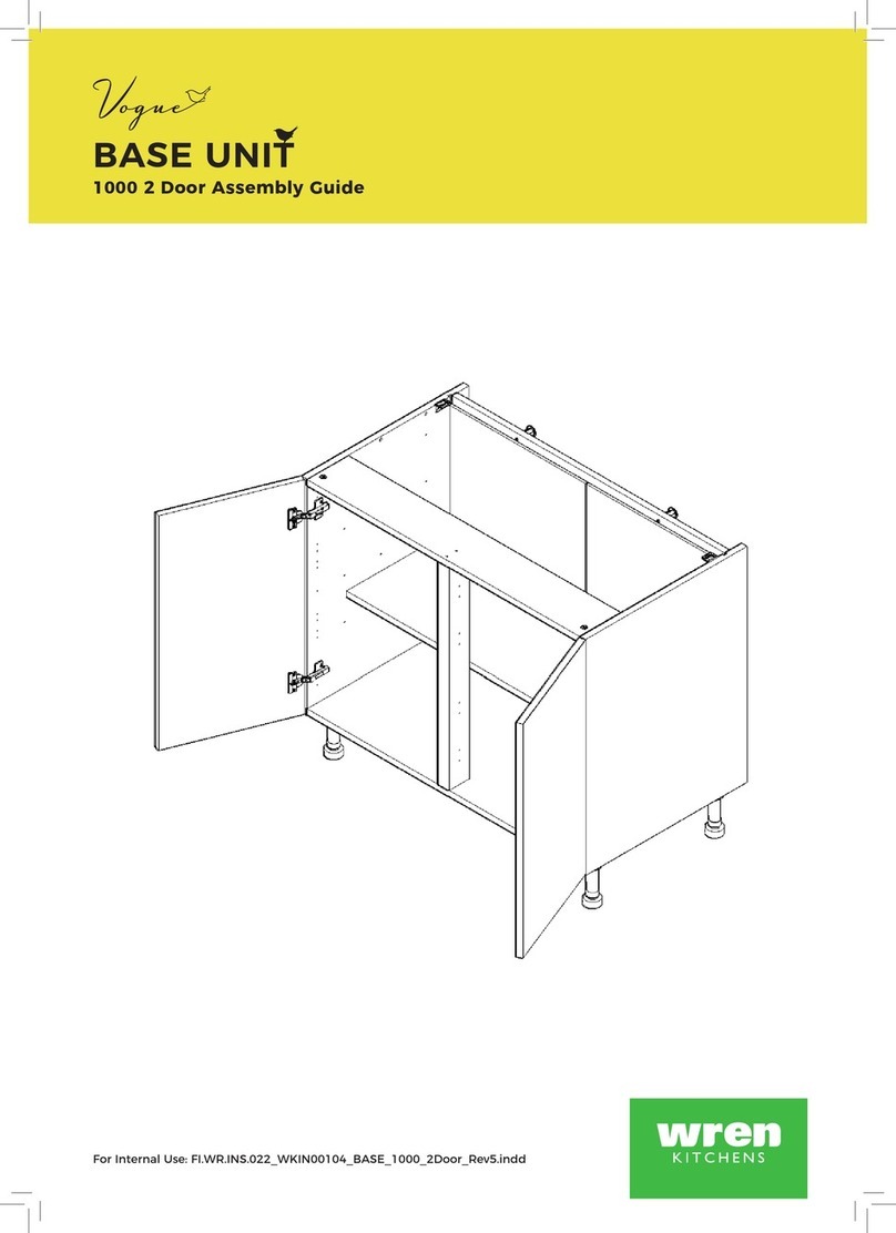
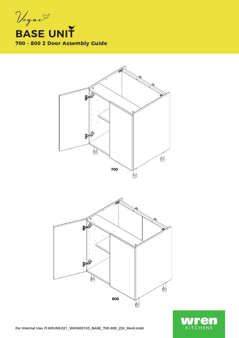
  9. Wren Kitchens Vogue BASE UNIT 800 2 Door User manual

Wren Kitchens Vogue BASE UNIT 800 2 Door User manual

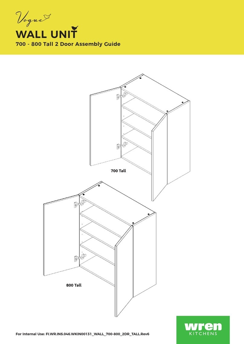
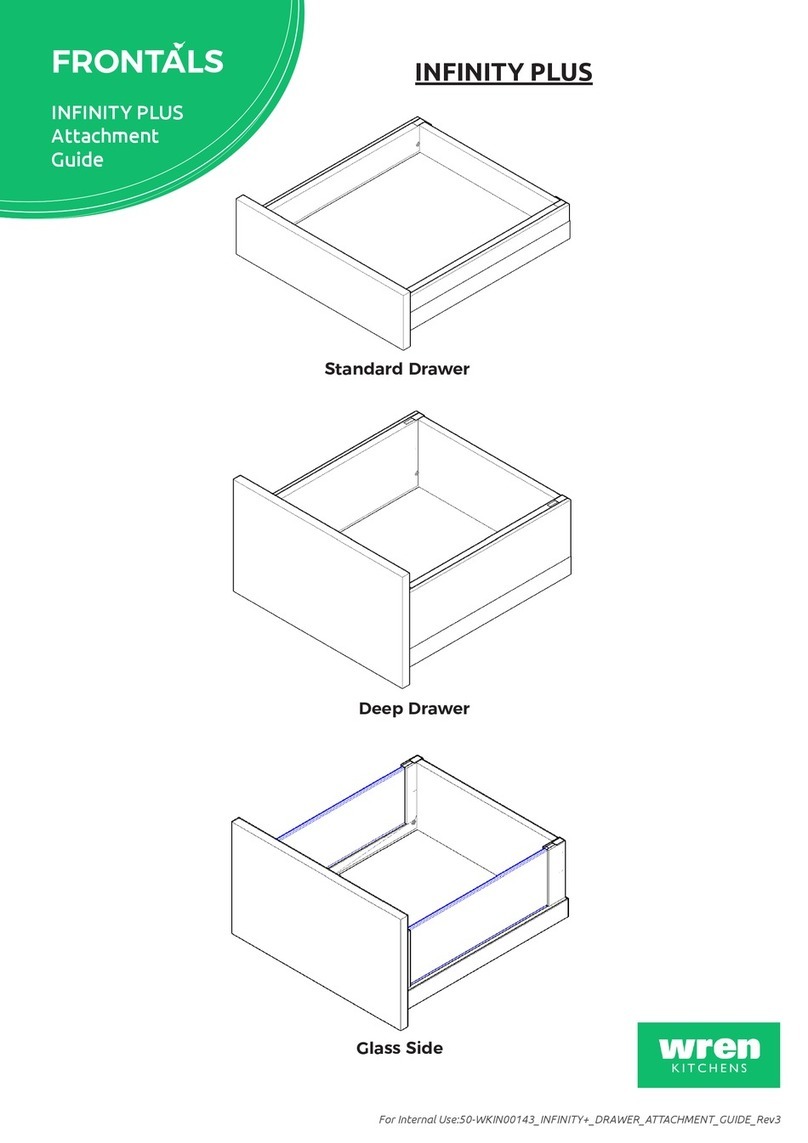
BASE UNIT
500-1000 Sink Hob 1-2 Dr Assembly Guide
For Internal Use: FR.WR.INS.057_WKIN00145_BASE_500-1000_SINK_HOB_1-DR.Rev5
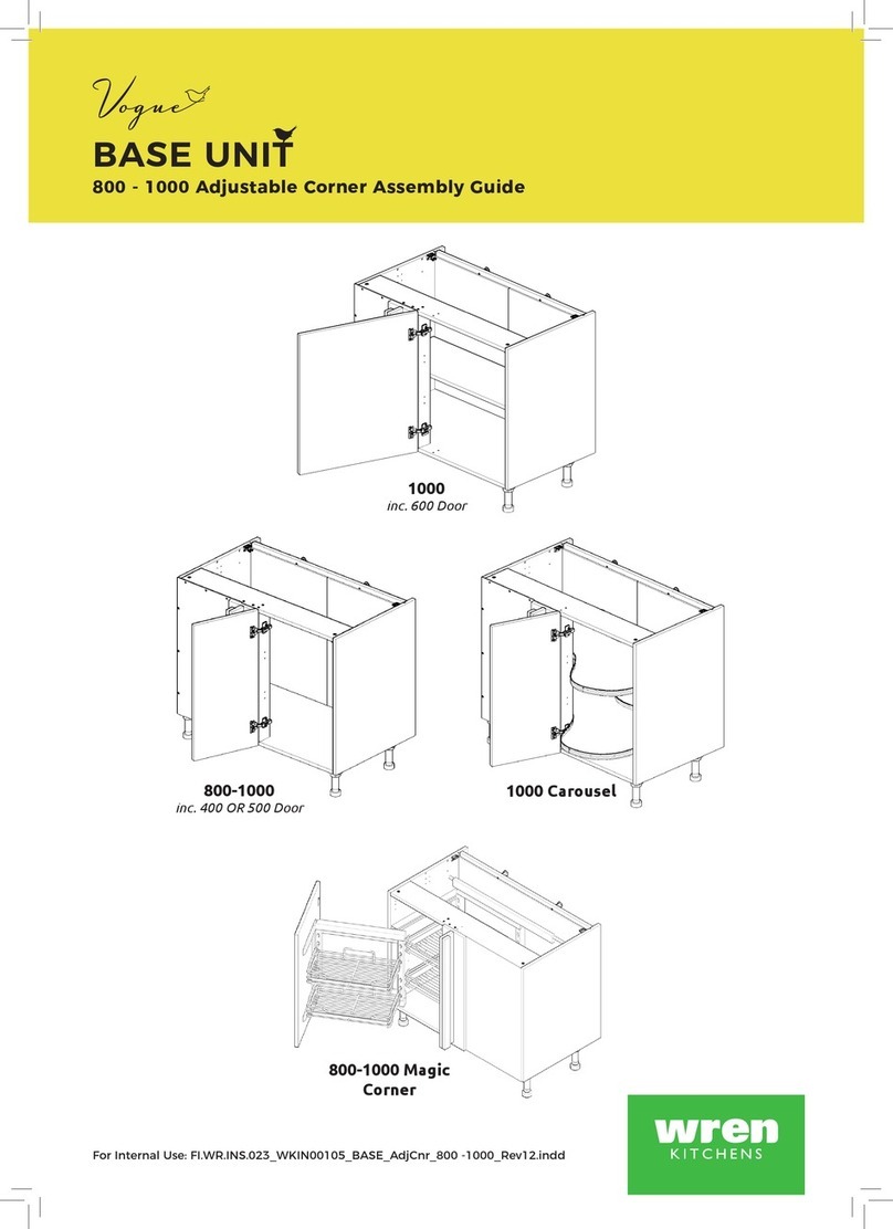
1000 2 Door
900 2 Door
600 1 Door 600 2 Door
500 1 Door
700 2 Door 800 2 Door
Page 1
BASE UNIT
500-1000 Sink Hob 1-2 Dr Assembly Guide
(F) x8
Wooden
Dowel
(G) x6
Cam Dowel
(Expanding)
(H) x6
Cam Lock
(K) x4
30mm
Screw
(L) x12
15mm
Screw
(N) x2
Door
Buer
(Z) x4
Shelf Peg
plastic
(M) x4
Cover
Cap
Panel B
x2 End Panel
Panel E
x1 Rail
Panel C
x1 Base Panel
Shelf
x1
Metal
Rail
x1
Legs
x4 or 5
as req’d
Frontal
(Packed separately)
x1 or 2
as req’d
Panel A
x1 Back Panel
(800 - 1000 folded)
REQUIRED TOOLS
NOT to be used
with CAM DOWEL
& CAM LOCK
Hinge Mounting Plate
x4 Inc Screws
Hinge
x4 Inc Screws
BEFORE YOU START
INSTALLATION
SHOULD BE
PERFORMED BY A
COMPETENT
PERSON ONLY.
THIS PRODUCT COULD
BE DANGEROUS
IF INCORRECTLY
INSTALLED
Page 2
For Internal Use:FR.WR.INS.057_WKIN00145_BASE_500-1000_SINK_HOB_1-DR.Rev5
Step 1.
Seat dowel (F) into holes in
both end panels (B) as shown.
Step 2.
Seat cam dowel (G) into holes in
both end panels (B) as shown.
Step 4.
Insert cam lock (H).
Do NOT tighten until Step 6.
All cam locks (H) are to be positioned facing the
outside of the unit carcase, for ease of tightening. Do NOT use power tools with
cam dowel (G) or cam lock (H)
Seat (G)
Cam Dowel
into hole as
shown.
B
B
E
C
GG
G
GG
FF
FF
F
F
B B
B
B
View from underside View from underside
H
G
G
H
Metal Rail
Insert
Metal Rail
Insert
Dowel (F), Cam Dowel (G)
& Metal Rail Screw
Location detail
Metal Rail
Step 3.
Attach panels (C) & (E) to panels (B), using dowels (F)
(orange) and cam dowel (G) (blue) in positions shown.
Insert metal rail as shown & secure with 2 x 15mm
screws (L) into panels (B).
C C
Page 3
BASE UNIT
500-1000 Sink Hob 1-2 Dr Assembly Guide
9mm
Step 5.
Slide back panel (A) into
groove of end panels (B).
The back Panel (A) is to be modied accordingly
to suit customer requirements, prior to inserting
into unit.
Once back panel (A) is in position, ensure the
panel is ush & square with bottom of
end panels (B).
Step 6.
Hand tighten all cam locks (H), this will
expand cam dowels (G) and tighten the
unit together.
Step 7.
Ensure unit is square. Secure back panel (A) with
3 or 4 x 30mm screws (K) equally spaced at the
lower end of back panel (A) into base panel (C),
as shown.
Ensure you screw into the centre of the base
panels (C) (9mm from the edge).
B
E
C
A
K
B
CA
600 unit used for example
Page 4
For Internal Use:FR.WR.INS.057_WKIN00145_BASE_500-1000_SINK_HOB_1-DR.Rev5
Leg position diagram
1000 unit used for example
C
B
B
Front
Front
Step 9.
Secure each of the legs into place with
4 x 15mm screws (L) per leg.
Step 8.
Position legs as shown.
600-800 width unit, 4 legs 1000 width units, 5 legs
Ensure legs are rotated to also provide support to the
end panels (B).
L
L
L
L
B
C
Step 10.
Push leg rmly down into leg base.
Adjust legs to 155mm before turning unit
upright. Once in situ level accordingly.
Page 5
BASE UNIT
500-1000 Sink Hob 1-2 Dr Assembly Guide
Step 11.
Attach hinge mounting plate
onto both end panel or panels,(B) as shown, using Screws
which are already positioned within the hinge plates.
Hinge side or sides to be mounted in accordance to
Customer Specic Kitchen Plan.
Screw into any side units using the 30mm screws (K)
provided to secure to the unit. Screw just to the rear
of the hinge plates at the top and bottom of both
sides of the unit, place cover caps (M) on the head to
conceal it.
Secure unit to wall using 2 x Screws. Drill 2 pilot
holes through the back rail into the wall and insert
wall plugs, tighten the screws.
94mm
94mm
126mm
126mm
B
From Bottom
From Top
Hinge Plates
K
Screw up through the front metal rail into worktop
to secure it in place.
Screws for attaching to walls and worktop are not provided as these vary depending
on materials, thickness and construction. Ensure appropriate xings for wall and
worktop construction are used. Please refer to the specialist worktop supplier if
these are required for solid surface worktops.
Page 6
For Internal Use:FR.WR.INS.057_WKIN00145_BASE_500-1000_SINK_HOB_1-DR.Rev5
Step 12.
Insert hinge in top & bottom
holes as shown below.
Step 13.
Secure hinges by tightening
2 x screws with hinge dowels
attached. These are already
positioned within the hinges.
Step 14.
Attach the door to unit
where required.
To attach door, clip hinge
onto hinge plate and click
to secure.
Hinge Cover Caps
Step 16.
Fit cover caps to hinge.
Adjust Soft close to suit.
Step 15.
Adjust hinge to suit. As shown below.
To adjust hinge using
a screw driver, tighten
or loosen as required at
points 1& 2.
Point 1- In - Out
Point 2- Left - Right
12
FRONTAL
HINGE
ADJUSTMENT
Hinge Plates
View from inside of unit
To release door,
pull catch as shown,
to release hinge from
the hinge plate.
The top and bottom
hinges MUST be
adjusted to the SAME
STRENGTH.
To Move the
hinge up/down,
loosen screws
A + B,
Manoeuvre
the door, then
re-tighten the
screws
A
B

Other manuals for Vogue BASE UNIT 800 2 Door

1

This manual suits for next models

6

Other Wren Kitchens Indoor Furnishing manuals
Wren Kitchens Vogue WALL BASE UNIT 700 WALL User manual

Wren Kitchens

Wren Kitchens Vogue WALL BASE UNIT 700 WALL User manual

Wren Kitchens Walk in 2070 User manual

Wren Kitchens

Wren Kitchens Walk in 2070 User manual

Wren Kitchens TOWER UNIT 2070 x 600 50/50 User manual

Wren Kitchens

Wren Kitchens TOWER UNIT 2070 x 600 50/50 User manual

Wren Kitchens 2070 User manual

Wren Kitchens

Wren Kitchens 2070 User manual

Wren Kitchens Vogue TOWER UNIT 2070 User manual

Wren Kitchens

Wren Kitchens Vogue TOWER UNIT 2070 User manual

Wren Kitchens BASE UNIT 600 User manual

Wren Kitchens

Wren Kitchens BASE UNIT 600 User manual

Wren Kitchens BASE UNIT 150 User manual

Wren Kitchens

Wren Kitchens BASE UNIT 150 User manual

Wren Kitchens Vogue BASE UNIT 600 2 Drawers Dummy User manual

Wren Kitchens

Wren Kitchens Vogue BASE UNIT 600 2 Drawers Dummy User manual

Wren Kitchens Vogue TOWER UNIT 300 Pull Out 2070 User manual
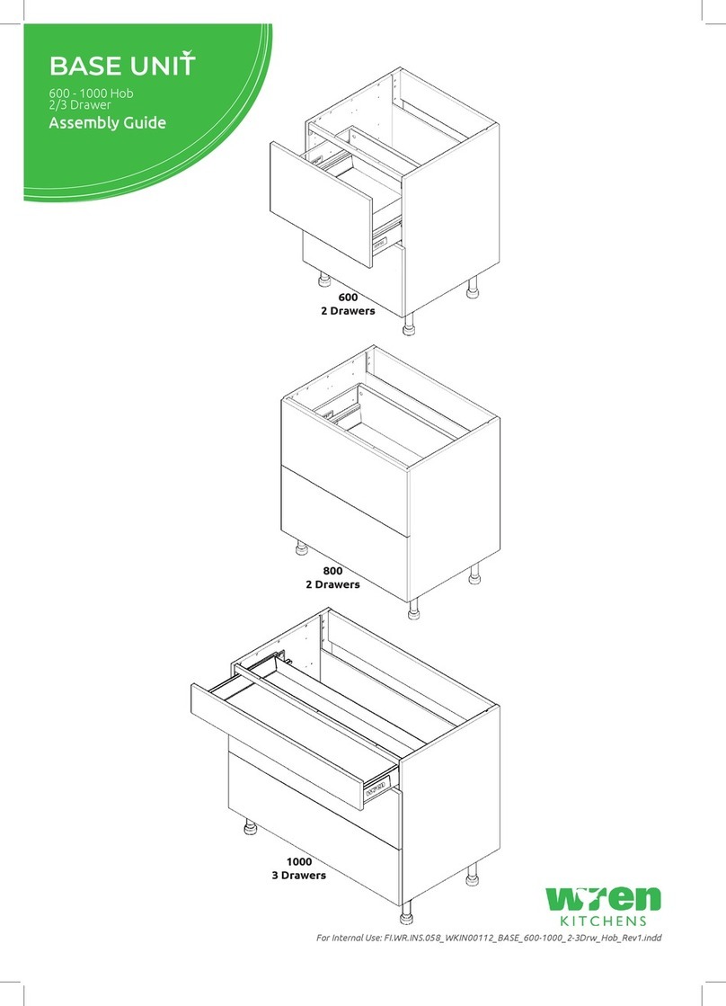
Wren Kitchens

Wren Kitchens Vogue TOWER UNIT 300 Pull Out 2070 User manual

Wren Kitchens Vogue BASE UNIT 300 1 Door User manual

Wren Kitchens

Wren Kitchens Vogue BASE UNIT 300 1 Door User manual

Wren Kitchens Vogue BASE UNIT 1000 2 Door User manual

Wren Kitchens

Wren Kitchens Vogue BASE UNIT 1000 2 Door User manual

Wren Kitchens Vogue BASE UNIT 972 L Corner User manual

Wren Kitchens

Wren Kitchens Vogue BASE UNIT 972 L Corner User manual

Wren Kitchens Vogue BASE UNIT 1000 Base Shallow User manual

Wren Kitchens

Wren Kitchens Vogue BASE UNIT 1000 Base Shallow User manual

Wren Kitchens Industrial Island User manual

Wren Kitchens

Wren Kitchens Industrial Island User manual

Wren Kitchens Base Cabinet Adjustable Corner Assembly instructions

Wren Kitchens

Wren Kitchens Base Cabinet Adjustable Corner Assembly instructions

Wren Kitchens L Corner Base Unit Assembly instructions

Wren Kitchens

Wren Kitchens L Corner Base Unit Assembly instructions

Wren Kitchens MIDWAY CABINET User manual

Wren Kitchens

Wren Kitchens MIDWAY CABINET User manual

Wren Kitchens FI.PK.FIT.004 User manual

Wren Kitchens

Wren Kitchens FI.PK.FIT.004 User manual

Wren Kitchens BASE UNIT 1000 User manual

Wren Kitchens

Wren Kitchens BASE UNIT 1000 User manual

Wren Kitchens Vogue WALL UNIT 700 Tall 2 Door User manual

Wren Kitchens

Wren Kitchens Vogue WALL UNIT 700 Tall 2 Door User manual

Wren Kitchens Vogue BASE UNIT 600 2 Drawer User manual

Wren Kitchens

Wren Kitchens Vogue BASE UNIT 600 2 Drawer User manual

Wren Kitchens BASE UNIT 600 User manual

Wren Kitchens

Wren Kitchens BASE UNIT 600 User manual

Wren Kitchens 2070 User manual

Wren Kitchens

Wren Kitchens 2070 User manual
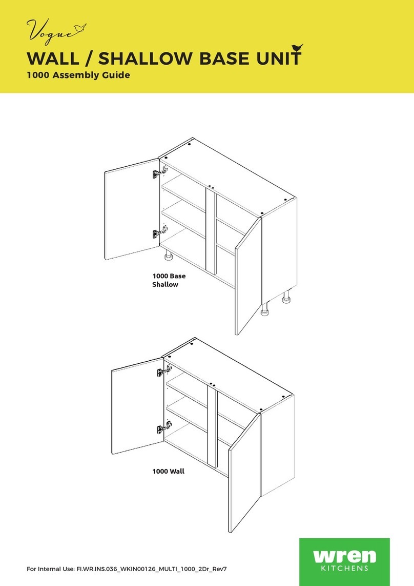
Wren Kitchens BASE UNIT 600 User manual
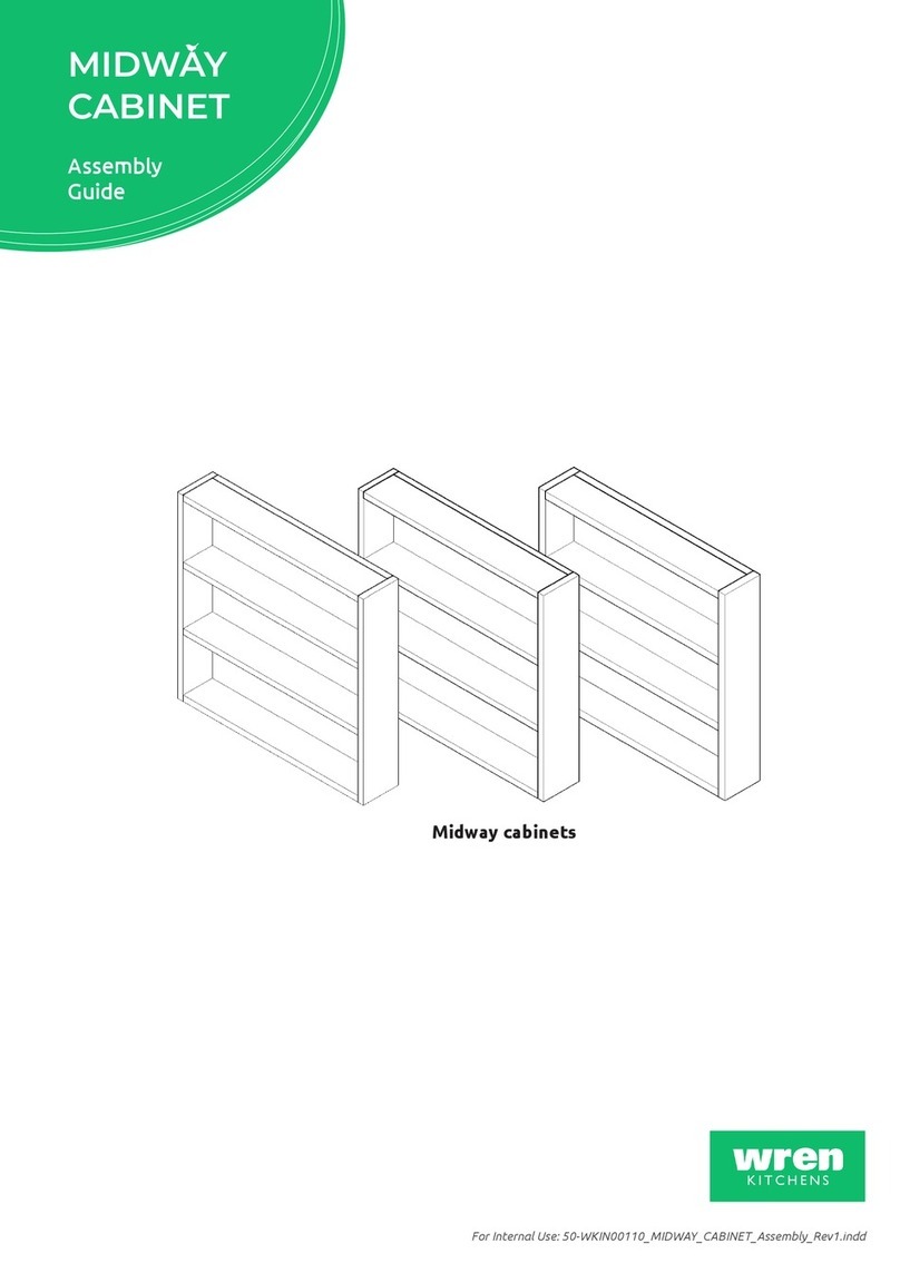
Wren Kitchens

Wren Kitchens BASE UNIT 600 User manual

Popular Indoor Furnishing manuals by other brands

Furniture of America CM-AC6140BG Assembly instructions

Furniture of America

Furniture of America CM-AC6140BG Assembly instructions

Dawn Venice AACCS-6001 installation guide

Dawn

Dawn Venice AACCS-6001 installation guide

Universal Furniture Universal explore home Nomad U181653 instruction sheet

Universal Furniture

Universal Furniture Universal explore home Nomad U181653 instruction sheet

Core Products Quebec QB310 Instruction leaflet

Core Products

Core Products Quebec QB310 Instruction leaflet

Costway HU10054 user manual

Costway

Costway HU10054 user manual

Lifetime 80123 owner's manual

Lifetime

Lifetime 80123 owner's manual

IKEA BASISK AA-171181-1 Assembly instructions

IKEA

IKEA BASISK AA-171181-1 Assembly instructions

Furniture of America CM3824PT-VN Assembly instructions

Furniture of America

Furniture of America CM3824PT-VN Assembly instructions

Home Decorators Collection SK-17429A Use and care guide

Home Decorators Collection

Home Decorators Collection SK-17429A Use and care guide

Poly-Tex FB3025-4 Assembly instructions

Poly-Tex

Poly-Tex FB3025-4 Assembly instructions

Forte LLGB01B Assembling Instruction

Forte

Forte LLGB01B Assembling Instruction

Rauch M1694 Assembly instructions

Rauch

Rauch M1694 Assembly instructions

HAUTAU ATRIUM quick start guide

HAUTAU

HAUTAU ATRIUM quick start guide

Teulat YOKO 2DR Assembly instructions

Teulat

Teulat YOKO 2DR Assembly instructions

Steelcase Bivi Rumble Seat manual

Steelcase

Steelcase Bivi Rumble Seat manual

NORTH STATES 4665 instruction manual

NORTH STATES

NORTH STATES 4665 instruction manual

Belnick Wing quick start guide

Belnick

Belnick Wing quick start guide

Canvas MONTCLERC 168-0007-8 Assembly instructions

Canvas

Canvas MONTCLERC 168-0007-8 Assembly instructions

manuals.online logo
manuals.online logoBrands
  • About & Mission
  • Contact us
  • Privacy Policy
  • Terms and Conditions

Copyright 2025 Manuals.Online. All Rights Reserved.