manuals.online logo
Brands
  1. Home
  2. •
  3. Brands
  4. •
  5. Zamel
  6. •
  7. Relay
  8. •
  9. Zamel EXTA PBM-02 User manual

Zamel EXTA PBM-02 User manual

BISTABLE RELAY PBM-02 INSTRUCTION MANUAL
APPEARANCE
ver. 0.4.2 _ 2006.06.26_08:00
FEATURES
TECHNICAL PARAMETERS
DESCRIPTION
PBM - 02
Input (supply) terminals : L, N
Input rated voltage: 230 V~
Input voltage tolerance: from -15 to +10 %
Nominal frequency: 50 / 60 Hz
Rated power consumption: 24 mA
Supply voltage control indicator: LED green
Release terminals: IN, IN, IN
Release control current: 930 µA
Central control terminals: Set, Reset
Power/relay supply indicator: LED red
Relay operating indicator: TEST button
Output relay parameters: 1NO - 16 A / 250 V AC1 4000 VA
Number of terminal clamps: 10
Section of connecting cables: from 0,2 to 2,50 mm2
Ambient temperature range: from -20 to +45 oC
Operating position: free
Mounting: TH35 rail (PN-EN 60715)
Protection degree: IP20 (PN-EN 60529)
Protection class: II
Overvoltage category: II
Pollution degree: 2
Rated impulse withstand voltage: 1 kV (PN-EN 61000-4-5)
Dimensions (height / width / depth): monomodular (17,5 mm) 90x17,5x66 mm
Weight: 80 g
Reference standards: PN-EN 60669-1; PN-EN 60669-2-1
PN-EN 61000-4-2,3,4,5,6,11
The bistable relay PBM-02 is used to
control lighting or other devices by means
of monomodular pushbuttons connected
in a parallel way. Pushing any button cau-
ses switching on or switching off the de-
vices connected to output terminals. The
controlling impulse can be L or N line sig-
nal. The Set and Rest control inputs allow
central control of a relay group. Using the
inner relay memory allows to remember
its current mode in cases of power supply
loss.

ZAMEL sp.j.
J.W. Dzida, K. Łodzińska
ul. Zielona 27, 43-200 Pszczyna, Poland
Tel. +48 (32) 210 46 65, Fax +48 (32) 210 80 04
www.zamel.pl,  [email protected]
The device is desig-
ned for one-phase in-
stallation and must be
installed in accordance
with standards valid in
a particular country.
The device should be
connected according to the details inclu-
ded in this operating manual. Installation,
connection and control should be carried
out by a qualied electrician staff, who act
in accordance with the service manual
and the device functions. Disassembling
of the device is equal with a loss of gua-
rantee and can cause electric shock. Be-
fore installation make sure the connec-
tion cables are not under voltage. The
cruciform head screwdriver 3,5 mm sho-
uld be used to instal the device.Improper
transport, storage, and use of the device
inuence its wrong functioning. It is not
advisable to instal the device in the follo-
wing cases: if any device part is missing
or the device is damaged or deformed. In
case of improper functioning of the devi-
ce contact the producer.
CAUTION
ی Bistable lighting control,
ی input rated indicator – LED green,
ی relay mode indicator – LED red,
ی central control function,
ی relay mode memory,
ی system releasing from the L or N
cable,
ی cooperation with monostable pus-
hbuttons equipped with illumination
lamps,
ی TEST function,
ی double-wire controll installation,
ی voltage relay output - one NO (norma
closed) contact max 16 A capacity.
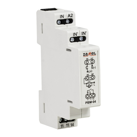
Output (load) relay
Supply voltage control indicator
Input supply terminals (L) Input supply terminals (N)
Relaytest
Power/relay supply indicator
Central control terminals (S, R)
Release terminals
(IN, IN, IN)
terminals (11, 11, 14)
GUARANTEE CARD
There is 24 months guarantee on the product

1. ZAMEL provides a two-year warranty for its products.
2. The ZAMEL warranty does not cover:
a) mechanical defects resulting from transport, loading / unloading or other circumstances,
b) defects resulting from incorrect installation or operation of ZAMEL products,
c) defects resulting from any changes made by CUSTOMERS or third parties, to products sold or equipment necessary
for the correct operation of products sold,
d) defects resulting from force majeure or other aleatory events for which ZAMEL is not liable.
3. All complaints in relation to the warranty must be provided by the CUSTOMER in writing to the retailer after discovering
a defect.
4. ZAMEL will review complaints in accordance with existing regulations.
5. The way a complaint is settled, e.g. replacement of the product, repair or refund, is left to the discretion of ZAMEL.
ver. 0.4.2 _ 2006.06.26_08:00

EXAMPLE OF INSTALLATION
CONNECTING
DIMENSIONS
PRODUCT FAMILY

The bistable relay ope-
rating the staircase lighting
(e.g. staircase lighting) are
controlled by means of mono
modular pushbuttons that
can be connected in a paral-
lel way.
The buttons can be pla-
ced in different places which
gives the possibility of cre-
ating universal lighting sy-
stems control.
TIME COURSE RELAY CAPACITY
INNER DIAGRAM
The bistable relay PBM-02 belongs to bi-
stable relay PBM product family.
1. Disconnect the power supply from the
mains by the phase fuse, the circuit-bre-
aker or the switch-disconnector that are
joined to the proper circuit,
 


3. Install PBM-01 device in the switchboard
on TH-35 DIN rail,
4. Connect the cables with the terminals
according to installing diagram,
5. Switch on the power supply from the
mains,
6. Push the TEST button several times to
check the relay operation correctness.
The device is ready to work after switching
on power supply. The relay operation correct-
ness can be checked by pushing the TEST
button placed on the front panel. The system
should switch on and off the load connected to
its output terminals. Mono modular pushbut-
tons connected in a parallel way are available
with backlit. Using the Set-Reset function the-
re is a possibility of relay group central control.
After voltage fading the relay mode is remem-
bered in the inner device memory.
t
U
t
t
SET
t
t
RESET
IN

In the bistable control systems signal separators can be used
to divide control signals into particular relay groups.
CENTRAL
SwITCH OFF
CENTRAL
SwITCH ON







L N
T
RS
IN
IN
IN
11
11
14

Other Zamel Relay manuals

Zamel exta PCM-09 User manual

Zamel

Zamel exta PCM-09 User manual

Zamel Exta PBM-03 User manual

Zamel

Zamel Exta PBM-03 User manual

Zamel PNM-10 User manual

Zamel

Zamel PNM-10 User manual

Zamel exta PPM - 05 User manual

Zamel

Zamel exta PPM - 05 User manual

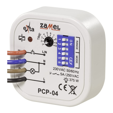
Zamel EXTA PCP-04 User manual

Zamel

Zamel EXTA PCP-04 User manual

Zamel exta PBM-07 User manual

Zamel

Zamel exta PBM-07 User manual

Zamel exta PB Series User manual

Zamel

Zamel exta PB Series User manual

Zamel Exta PBM-04/U User manual

Zamel

Zamel Exta PBM-04/U User manual

Zamel exta PCM-01 User manual

Zamel

Zamel exta PCM-01 User manual

Zamel exta PNM-10 User manual

Zamel

Zamel exta PNM-10 User manual

Zamel EXTA PCP-06 User manual

Zamel

Zamel EXTA PCP-06 User manual

Zamel EXTA PBM-03 User manual

Zamel

Zamel EXTA PBM-03 User manual

Zamel PCM-02/24V User manual

Zamel

Zamel PCM-02/24V User manual

Zamel PCM-07/U User manual

Zamel

Zamel PCM-07/U User manual

Zamel PNM-32 User manual

Zamel

Zamel PNM-32 User manual

Zamel EXT10000084 User manual

Zamel

Zamel EXT10000084 User manual

Zamel EXTA PCM-11 User manual

Zamel

Zamel EXTA PCM-11 User manual

Zamel Exta PCM-02/U User manual

Zamel

Zamel Exta PCM-02/U User manual

Zamel Exta PBM-07 User manual

Zamel

Zamel Exta PBM-07 User manual

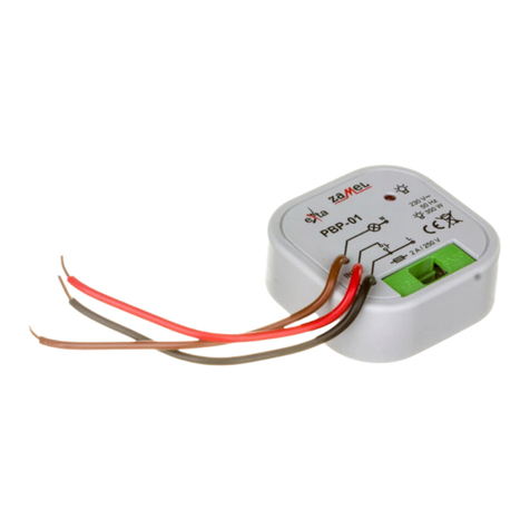
Zamel EXTA PBP-01 User manual

Zamel

Zamel EXTA PBP-01 User manual

Zamel PCM-04/24V User manual

Zamel

Zamel PCM-04/24V User manual

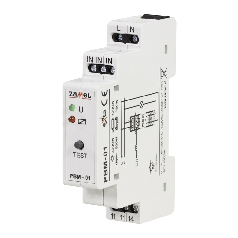
Zamel PBM-01 User manual

Zamel

Zamel PBM-01 User manual

Zamel PCM-08 User manual

Zamel

Zamel PCM-08 User manual

Popular Relay manuals by other brands

Malmbergs 4028682 instruction manual

Malmbergs

Malmbergs 4028682 instruction manual

Reer SR SELECT Quick installation guide

Reer

Reer SR SELECT Quick installation guide

Crouzet MWS manual

Crouzet

Crouzet MWS manual

Schrack LSD3 Series operating instructions

Schrack

Schrack LSD3 Series operating instructions

Schweitzer Engineering Laboratories SEL-411L Application guide

Schweitzer Engineering Laboratories

Schweitzer Engineering Laboratories SEL-411L Application guide

Taco FuelMizer SR501-OR-4 instruction sheet

Taco

Taco FuelMizer SR501-OR-4 instruction sheet

TECO SG2 PLR user manual

TECO

TECO SG2 PLR user manual

Woodward MFD 11 Packages manual

Woodward

Woodward MFD 11 Packages manual

ABB System pro M RLI manual

ABB

ABB System pro M RLI manual

Pilz PNOZSIGMA Series operating instructions

Pilz

Pilz PNOZSIGMA Series operating instructions

Elko HRN- 57 manual

Elko

Elko HRN- 57 manual

ASO Safety Solutions ISK 70-755 operating manual

ASO Safety Solutions

ASO Safety Solutions ISK 70-755 operating manual

Allen-Bradley MINOTAUR MSR144RTP manual

Allen-Bradley

Allen-Bradley MINOTAUR MSR144RTP manual

Pilz 22 772-04 operating instructions

Pilz

Pilz 22 772-04 operating instructions

Eaton Digitrip 3000 series Installation, operation and maintenance instructions

Eaton

Eaton Digitrip 3000 series Installation, operation and maintenance instructions

GE IAC60A instructions

GE

GE IAC60A instructions

Eaton 473-N Instruction leaflet

Eaton

Eaton 473-N Instruction leaflet

ADTRAN TSU IQ+ user manual

ADTRAN

ADTRAN TSU IQ+ user manual

manuals.online logo
manuals.online logoBrands
  • About & Mission
  • Contact us
  • Privacy Policy
  • Terms and Conditions

Copyright 2025 Manuals.Online. All Rights Reserved.