PPM - 05 PRIORITY RELAY INSTRUCTION MANUAL
Zakład Mechaniki i Elektroniki
ZAMEL sp.j.
J.W. Dzida, K. Łodzińska
ul. Zielona 27, 43-200 Pszczyna, Poland
Tel. +48 (32) 210 46 65, Fax +48 (32) 210 80 04
FEATURES
TECHNICAL DATA
DESCRIPTION
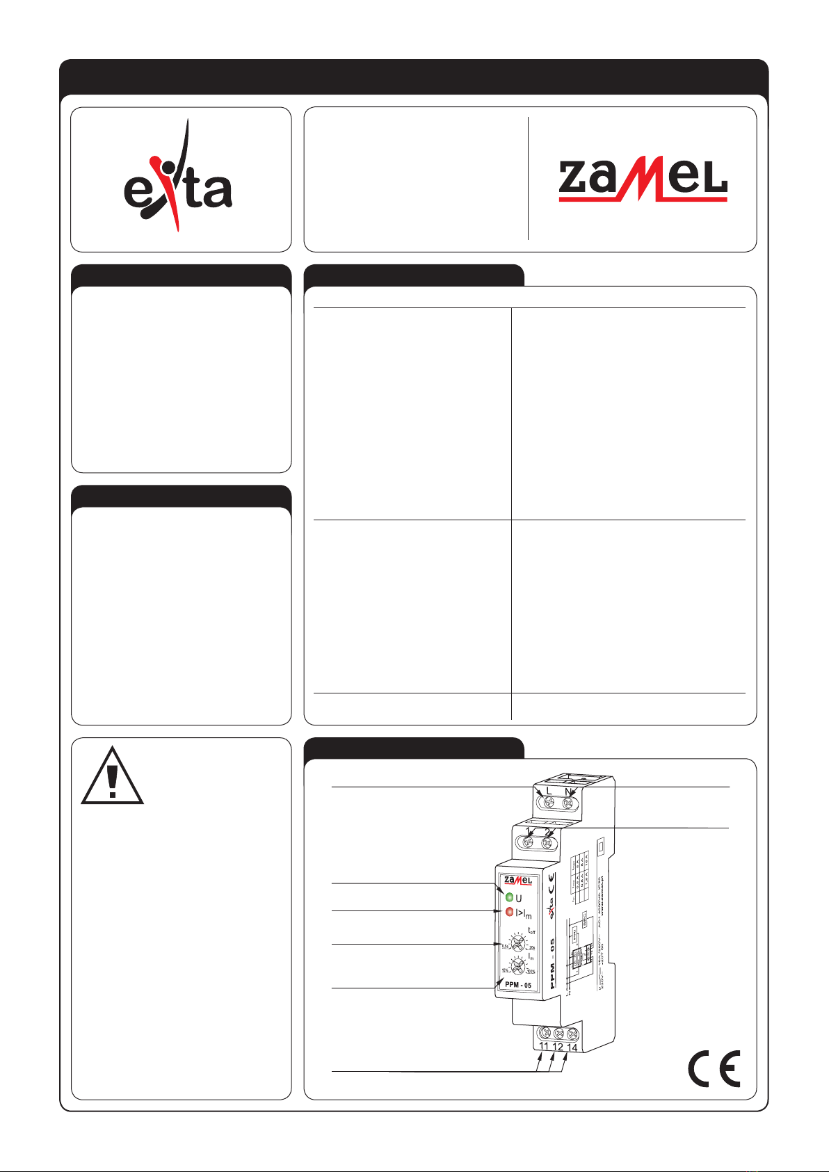
APPERANCE
PPM - 05
Power terminals: L, N
Rated voltage: 230 V~
Rated voltage tolerance: -15 ÷ +10 %
Rated frequency: 50 / 60Hz
Rated current: 34 mA
Measure termianals: 1, 2
Current threshold adjustment:
0,5 ÷ 5 A (hysteresis ~5%) - for PPM-05/5
0,8 ÷ 8 A (hysteresis. ~5%) - for PPM-05/8
1,6 ÷ 16 A (hysteresis ~5%) - for PPM-05/16
Current measure tolerance: ≤ 20%
OFF-time delay: 0,5 ÷ 20 s
Supply voltage indicator: green LED
Current threshold exceed indicator: red LED
Relay contacts parameters: 1NO/NC - 16 A / 250 V AC1 4000 VA
Connection terminals quantity: 7
Connection wire section: 0,2 ÷ 2,5 mm2
Operating temperature: -20 ÷ +60 oC
Operating position: optional
Casing fastening: TH 35 rail (according to PN-EN 60715)
Casing IP: IP20 (PN-EN 60529)
Protection class: II
Overvoltage category: II
Pollution level: 2
Dimensions: single-module (17,5 mm) 90x17,5x66 mm
Weight: 88 g
Standard conformity: PN-EN 60730-1; PN-EN 60730-2-1
PN-EN 61000-4-2,3,4,5,6,11
ی Both priority and non-priority circuits
control,
ی
Three product versions, in dependen-
ce of the current level
,
ی Power supply indicator,
ی Current threshold indicator,
ی Continuous delay time adjustment,
ی Continuous current threshold adjust-
ment,
ی Measure circuit separated voltaic,
ی Relay voltage output, changeover con-
tact, maximum load 16 A,
ی Mounted on TH 35 rail.
The PPM-05 priority relay is designed
for current control in priority and / or non-
priority load circuits. When the current mea-
sured on measure terminals (1, 2) exceeds
the preset value, the device will switch-OFF
a non-priority receiver with the preset delay
time. The current threshold and delay time
may be adjusted by the user. It is possible to
protect the electrical network against over-
loads by means of the relay, but the device
may not replace a current-limiting circuit-
breaker.
Relayoutput
Supplyvoltage indicator
Power terminal (L)Power terminal (N)
Measure lead
terminals (1, 2)
terminals (11, 12, 14)
Current threshold setting
Current threshold exceed
indicator
OFF-time delay
setting
The timer should be
connected to a single-
phase system accordin-
gly to current standards.
The device connections
will be described in this
manual. Only qualied electricians are
allowed to assembly, connect and ad-
just the timer. It is necessary to read this
manual before the timer mounting. Do
not disassembly the timer casing or you
will lose any warranty rights and expo-
se yourself to the electric shock hazard.
Before mounting operation make sure
of disconnecting the connection wires
from the electric network. The timer
should be carried, stored and used in
an appropriate way. Do not mount the
timer in case of any device parts lack,
damage or deformation. In case of mal-
function please notify the manufacturer.
CAUTION


