manuals.online logo
Brands
  1. Home
  2. •
  3. Brands
  4. •
  5. Zamel
  6. •
  7. Relay
  8. •
  9. Zamel Exta PBM-07 User manual

Zamel Exta PBM-07 User manual

BISTABLE RELAY PBM-07
MANUAL INSTRUCTION
ZAMEL Sp. z o.o.
ul. Zielona 27, 43-200 Pszczyna, Poland
tel. +48 (32) 210 46 65, fax +48 (32) 210 80 04
www.zamel.com, e-mail: [email protected]
PBM-07_inst_ext_GB | 05.05.21
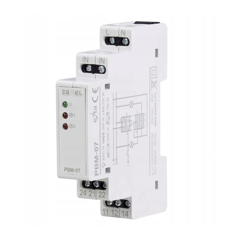
APPEARANCE
FEATURES
DESCRIPTION
● control of lighting and other devices
according to a defined sequence,
● output status indicated by red LEDs
(2 x red LED),
●
power supply indication (1 x green LED),
● system release only from the “L” line,
● possibility of cooperation with unipolar
backlit push buttons,
● two-wire control installation,
● two independent relay outputs – (dry
contacts) 2 NO /NC contacts with a ma-
ximum load of 16 A,
● mounting in distribution boards
(TH35 rail).
The PBM-07 bistable relay is used to con-
trol lighting or any other device by means
of unipolar push buttons connected in
a parallel way. The relay is equipped with
two outputs activated by means of impuls-
es given to the (IN) input. It allows to con-
trol two circuits / branches simultaneously.
The control impulse must be the “L” line
signal. The trigger input structure enables
cooperation with backlit push buttons (in-
cluding LED backlight). The total current
of backlight for the (IN) input can not ex-
ceed 1,5 mA. The device is designed to be
mounted in distribution boards (TH35 rail).
LEDs on the front panel indicate power
supply (green LED) and the output status
(2 x red LED).
TECHNICAL DATA
Input (supply) terminals: L, N
Nominal supply voltage: 230 V AC
Nominal supply voltage tolerance: -15 ÷ +10 %
Nominal frequency: 50 Hz
Nominal power consumption: stand-by: 0,4 W
2 active outputs: 1,1 W
Optical signalling of relay status:
2x red LED
Release terminals: IN, IN
Release control current: 7,5 mA
Cooperation with backlit push buttons: yes
Total current of the push button backlight: < 1,5 mA
Minimum impulse release time: 70 ms
Output devices: 2 x relays
Relay contact parameters: NO/NC – 16 A / 250 VAC
Number of connection terminals: 10
Cross-section of connection cables: 0,2 ÷ 2,5 mm2
Operating temperature range: -20 ÷ +45 oC
Operating position: free
Casing mounting: TH35 rail
Casing protection degree: IP20
Overvoltage category: II
Pollution degree: 2
Dimensions: 90 x 17,5 x 66 mm
Weight: 0,090 kg
Connect this product to a
single-phase power system ac-
cording to applicable electrical
and safety standards and regu-
lations. See this Manual for the
wiring instructions. Installation,
wiring and adjustment/setting shall only be
done by qualied electricians who have read
and understood this User Manual and the
functions of the product. Do not open or oth-
erwise disassemble the product housing; oth-
erwise the product warranty will be void and
an electrocution hazard may occur. Prior to
installing and wiring this product, make sure
that the wiring to be connected is not live. The
conditions and methods of transport, storage
and operation of this product may affect its
performance. Do not install the product if any
of its components are missing, the product is
damaged or deformed in any way. If any mal-
functions are found, consult the manufacturer.
CAUTION
Do not dispose of this device with other
waste! In order to avoid harmful effects on
the environment and human health, the
used device should be stored in designated
areas. For this purpose, you can dispose
of household waste free of charge and in
any quantity to a collection point set up,
as well as to the shop when you buy new
equipment.
Input (supply) terminal (L)
PK1 (11,14,12) output relay
terminals
PK2 (21,24,22) output relay
terminals
Input (supply) terminal (N)
Release terminals (IN)
Power supply indicator
PK1 status indicator
PK2 status indicator

OPERATION MODES
MOUNTING, FUNCTIONING
CASING DIMENSIONS
1. Disconnect power supply by the phase
fuse, the circuit-breaker or the switch-dis-
connector combined to the proper circuit.
2. Check if there is no voltage on the connec-
tion cables by means of a special measur-
ing equipment.
3. Install PBM-07 on a TH35 rail in the distri-
bution board.
4. Connect the device cables with the ter-
minals in accordance with the installing
diagram.
5. Switch on the power supply from the mains.
6. Press a push button connected to the (IN)
release input a few times to check if the
device operates properly.
After supply voltage has been applied,
the device is ready to operate. Correct oper-
ation of the PBM-07 relay can be checked by
pressing a push button connected to the re-
lease terminal (IN) a few times. The system
should switch on / switch off loadings con-
nected to its output terminals (PK1-11,12,14
and PK2-21,22,24). Unipolar push buttons
can be connected in a parallel way and pro-
vide lighting control of several places. These
push buttons are available with backlight.
CAUTION:
PBM-07 can cooperate with backlit push
buttons. The total current consumption
before backlight can not exceed 1,5 mA.
The (IN) release input structure is used to
a continuous triggering.
CONNECTION
After supply voltage has been applied or after its decay both relays PK1 and PK2 are switched off.
In case the subsequent impulses are given to the (IN) input, the device will:
• switch on both output relays,
• switch off both output relays.
General impulse release requirements:
• The PBM-07 relay reacts to the falling edge of the release impulse (reaction to the button release
connected to the (IN) input).
• Minimum duration of impulse release – 70 ms.
• Minimum time interval between subsequent impulses – 250 ms.
CAPACITY
The above values are only indicative. They
depend, to a large extent, on a particular
capacity (mainly it refers to LED bulbs, ener-
gy-saving lamps and switched-mode power
supplies), switching on frequency and operat-
ing conditions.
WARRANTY CARD
There is a 24 month guarantee on the product
Salesman stamp and signature, date of sale
1. ZAMEL Sp. z o.o. assures a 24 month guarantee for the product.
2. The manufacturer’s guarantee does not cover any of the following actions:
a) mechanical damage during transport, loading / unloading or under other circumstances,
b) damage caused by incorrect product mounting or misuse,
c) damage caused by unauthorised modications made by the PURCHASER or any third parties to the product or
any other devices
required for the product functioning,
d) damage caused by Act of God or any other incidents independent of the manufacturer – ZAMEL Sp z o.o.
3. The PURCHASER shall lay any claims in writing in the place of purchase or to ZAMEL Sp. z o.o.
4. ZAMEL Sp. z o.o. is liable for processing any claim according to current Polish legislation.
5. ZAMEL Sp. z o.o. shall process the claim at its own discretion: product repair, replacement or money return.
6. The PURCHASER’s statutory rights in any applicable legislation whether against the retailer arising from the pur-
chase contract or otherwise are not affected by this warranty.
2000 W
1000 W
500 W
750 W
250 W
LED
t
IN
PK1
PK2
t
t
t
U
>70 ms >250 ms
< 1,5 mA

Other Zamel Relay manuals

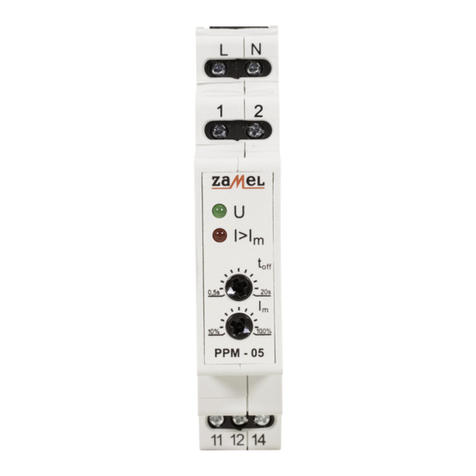
Zamel exta PPM - 05 User manual

Zamel

Zamel exta PPM - 05 User manual

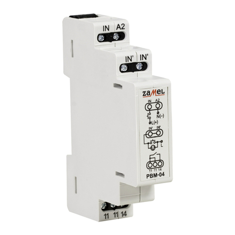
Zamel Exta PBM-04/U User manual

Zamel

Zamel Exta PBM-04/U User manual

Zamel PNM-32 User manual

Zamel

Zamel PNM-32 User manual

Zamel Exta PBM-03 User manual

Zamel

Zamel Exta PBM-03 User manual

Zamel EXTA PBP-01 User manual

Zamel

Zamel EXTA PBP-01 User manual

Zamel Exta PCM-02/U User manual

Zamel

Zamel Exta PCM-02/U User manual

Zamel PCM-07/U User manual

Zamel

Zamel PCM-07/U User manual

Zamel exta PB Series User manual

Zamel

Zamel exta PB Series User manual

Zamel PBM-01 User manual

Zamel

Zamel PBM-01 User manual

Zamel EXTA PBM-02 User manual

Zamel

Zamel EXTA PBM-02 User manual

Zamel exta PBM-07 User manual

Zamel

Zamel exta PBM-07 User manual

Zamel PCM-02/24V User manual

Zamel

Zamel PCM-02/24V User manual

Zamel PCM-08 User manual

Zamel

Zamel PCM-08 User manual

Zamel PNM-10 User manual

Zamel

Zamel PNM-10 User manual

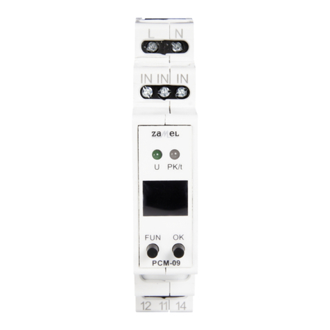
Zamel exta PCM-09 User manual

Zamel

Zamel exta PCM-09 User manual

Zamel EXTA PBM-03 User manual

Zamel

Zamel EXTA PBM-03 User manual

Zamel exta PNM-10 User manual

Zamel

Zamel exta PNM-10 User manual

Zamel exta PCM-01 User manual

Zamel

Zamel exta PCM-01 User manual

Zamel PCM-04/24V User manual

Zamel

Zamel PCM-04/24V User manual

Zamel EXTA PCP-04 User manual

Zamel

Zamel EXTA PCP-04 User manual

Zamel EXTA PCM-11 User manual

Zamel

Zamel EXTA PCM-11 User manual

Zamel EXT10000084 User manual

Zamel

Zamel EXT10000084 User manual

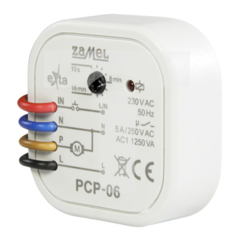
Zamel EXTA PCP-06 User manual

Zamel

Zamel EXTA PCP-06 User manual

Popular Relay manuals by other brands

Elko HRF-10 manual

Elko

Elko HRF-10 manual

FANOX SIL-A A Series user manual

FANOX

FANOX SIL-A A Series user manual

Eaton C440/XTOE user manual

Eaton

Eaton C440/XTOE user manual

GE Baker Hughes Masonelian BR200 instruction manual

GE

GE Baker Hughes Masonelian BR200 instruction manual

Circutor RGU-10C quick start guide

Circutor

Circutor RGU-10C quick start guide

Siemens Argus 7SR21 installation guide

Siemens

Siemens Argus 7SR21 installation guide

Pilz PNOZ X10 operating instructions

Pilz

Pilz PNOZ X10 operating instructions

SEB IDM8N user manual

SEB

SEB IDM8N user manual

Schweitzer Engineering Laboratories SEL-749M instruction manual

Schweitzer Engineering Laboratories

Schweitzer Engineering Laboratories SEL-749M instruction manual

GE HFA151 instructions

GE

GE HFA151 instructions

NK TECHNOLOGIES ATS Series instructions

NK TECHNOLOGIES

NK TECHNOLOGIES ATS Series instructions

Omron G9SA-501 user manual

Omron

Omron G9SA-501 user manual

GMI D5091S Instruction & safety manual

GMI

GMI D5091S Instruction & safety manual

Hella marine 5XA 998 572-001 Installation & operating instructions

Hella marine

Hella marine 5XA 998 572-001 Installation & operating instructions

Eltako AR12-001-230V 0,1-25A manual

Eltako

Eltako AR12-001-230V 0,1-25A manual

Pepperl+Fuchs KFD0-RSH-1.4S.PS2 Safety manual

Pepperl+Fuchs

Pepperl+Fuchs KFD0-RSH-1.4S.PS2 Safety manual

Honeywell R4343D instruction sheet

Honeywell

Honeywell R4343D instruction sheet

Westinghouse KV-1 instructions

Westinghouse

Westinghouse KV-1 instructions

manuals.online logo
manuals.online logoBrands
  • About & Mission
  • Contact us
  • Privacy Policy
  • Terms and Conditions

Copyright 2025 Manuals.Online. All Rights Reserved.