manuals.online logo
Brands
  1. Home
  2. •
  3. Brands
  4. •
  5. Zamel
  6. •
  7. Relay
  8. •
  9. Zamel PCM-04/24V User manual

Zamel PCM-04/24V User manual

TIME RELAY PCM-04/24V INSTRUCTION MANUAL
Zakład Mechaniki i Elektroniki
ZAMEL sp.j.
J.W. Dzida, K. Łodzińska
ul. Zielona 27, 43-200 Pszczyna, Poland
Tel. +48 (32) 210 46 65, Fax +48 (32) 210 80 04
www.zamelcet.com, e-mail: [email protected]
VER. 002_13.01.2010
The device is designed for
one-phase installation and
must be installed in accor-
dance with standards valid
in a particular country. The
device should be connected
according to the details inc-
luded in this operating manual. Installation,
connection and control should be carried
out by a qualied electrician staff, who act
in accordance with the service manual and
the device functions. Disassembling of the
device is equal with a loss of guarantee
and can cause electric shock. Before in-
stallation make sure the connection cables
are not under voltage. The cruciform head
screwdriver 3,5 mm should be used to instal
the device. Improper transport, storage,
and use of the device inuence its wrong
functioning. It is not advisable to instal the
device in the following cases: if any device
part is missing or the device is damaged or
deformed. In case of improper functioning
of the device contact the producer.
CAUTION
APPEARANCE
The symbol stands for selective
collection of electrical
and electronic devices.
Placing used devices with other
waste is not allowed
FEATURES
TECHNICAL PARAMETERS
DESCRIPTION
● 10 operating modes (external release
or from power supply voltage),
● supply voltage control signal - LED
green,
● power/relay supply indicator and time
measure - LED red,
● time measure accuracy,
● wide time adjustment range,
● constant switch on, switch off func-
tion,
● voltage relay output - 1 change over
contact (NO/NC) contact max 16 A
capacity,
● monomodular casing,
● TH 35 DIN rail installation.
The multifunctional time relay
PCM-04/24V has a time function in au-
tomation and control systems. It is equ-
ipped with 10 independent operating
modes released by power supply vol-
tage or external impulse command (co-
ming from L or N line). It has a wide time
adjustment range and constant switch
on/off function. The mode change is po-
ssible without waiting for the current cyc-
le to be nished.
PCM-04/24V
Input (supply) terminals: -/~ , +/~
Input rated voltage: 24 V AC/DC
Input voltage tolerance: from -15 to +10 %
Supply voltage control indicator: LED green
Nominal frequency: 50 / 60 Hz
Rated power consumption: 25 mA
External release terminals: IN, IN, IN (released from L or N)
Release current: 510 μA
Operating modes number: 10
Time adjustment range t: from 0,1s to 10days (step+smooth)
Time measure accuracy: 0,2 %
Power/relay supply indicator and time measure: LED red
Output relay parameters: 1NO/NC-16 A/250 V AC1 4000 VA
Number of terminal clamps: 8
Section of connecting cables: from 0,2 to 2,50 mm2
Ambient temperature range: from -20 to +60 oC
Operating position: free
Mounting: TH 35 rail (PN-EN 60715)
Protection degree: IP20 (PN-EN 60529)
Protection class: II
Overvoltage category: II
Pollution degree: 2
Rated impulse withstand voltage: 2 kV (PN-EN 61000-4-5)
Dimensions (height / width / depth): monomodular (17,5 mm) 90x17,5x66 mm
Weight: 0,08 kg
Reference standards: PN-EN 60730-1
PN-EN 60730-2-7
PN-EN 61000-4-2,3,4,5,6,11
Output(load)
Supplyvoltage control indicator
Inputsupplyterminals (-/~)
Inputsupplyterminals (+/~)
Smooth time adjustment
Operating mode choice
Power/relaysupplyindicator
(time measure signal)
relay terminals (11, 12, 14)
Time adjustment
choice
External release terminals
(IN, IN, IN)
VER. 002_13.01.2010
MOUNTING FUNCTIONING
1. Disconnect the power supply from the
mains by the phase fuse, the circuit-
breaker or the switch-disconnector
that are joined to the proper circuit,
2. Check if there is no voltage on con-
nection cables by means of a spe-
cial measure equipment,
3. Install PCM-04/24V device in the
switchboard on TH 35 DIN rail,
4. Connect the cables with the terminals
according to installing diagram,
5. Switch on the power supply from the
mains,
6. Choose the required operating mode
by Mode knob,
7. Adjust the time using the TIME knobs
t = TIMExRANGE.
DIMENSIONS
CONNECTING
ATTENTION!
The rele-
ase impulse
can by a signal from L or N line. The opera-
ting mode change (in any moment) causes an
immediate zeroing of the measured time and
starting the new chosen operating mode. Time
adjustment choices are made without delay.
1411 12
GUARANTEE CARD
There is 24 months guarantee on the product
Salesman stamp and signature, date of sale
1. ZMIE ZAMEL SP. J. assures 24 months guarantee for the product.
2. The manufacturer’s guarantee does not cover any of the following actions:
a) mechanical damage during transport, loading / unloading or under other circumstances,
b) damage caused by incorrect product mounting or misuse,
c) damage caused by unauthorised modications made by the PURCHASER or any third parties to the product or any other devices
needed for the product functioning,
d) damage caused by Act of God or any other incidents independent of the manufacturer.
3. The PURCHASER shall lay any claims in writing to the dealer or ZMIE ZAMEL SP. J.
4. ZMIE ZAMEL SP. J. is liable for processing any claim according to current Polish legislation.
5. ZMIE ZAMEL SP. J. shall process the claim at its own discretion: product repair, replacement or money return.
6. The manufacturer’s guarantee is valid in the Republic of Poland.
7. The PURCHASER’s statutory rights in any applicable legislation whether against the retailer arising from the purchase contract or
otherwise are not affected by this warranty.
Power supply voltage release:
AJ
B
C
DEFG
H
I
M
O
D
E
U
A
tt
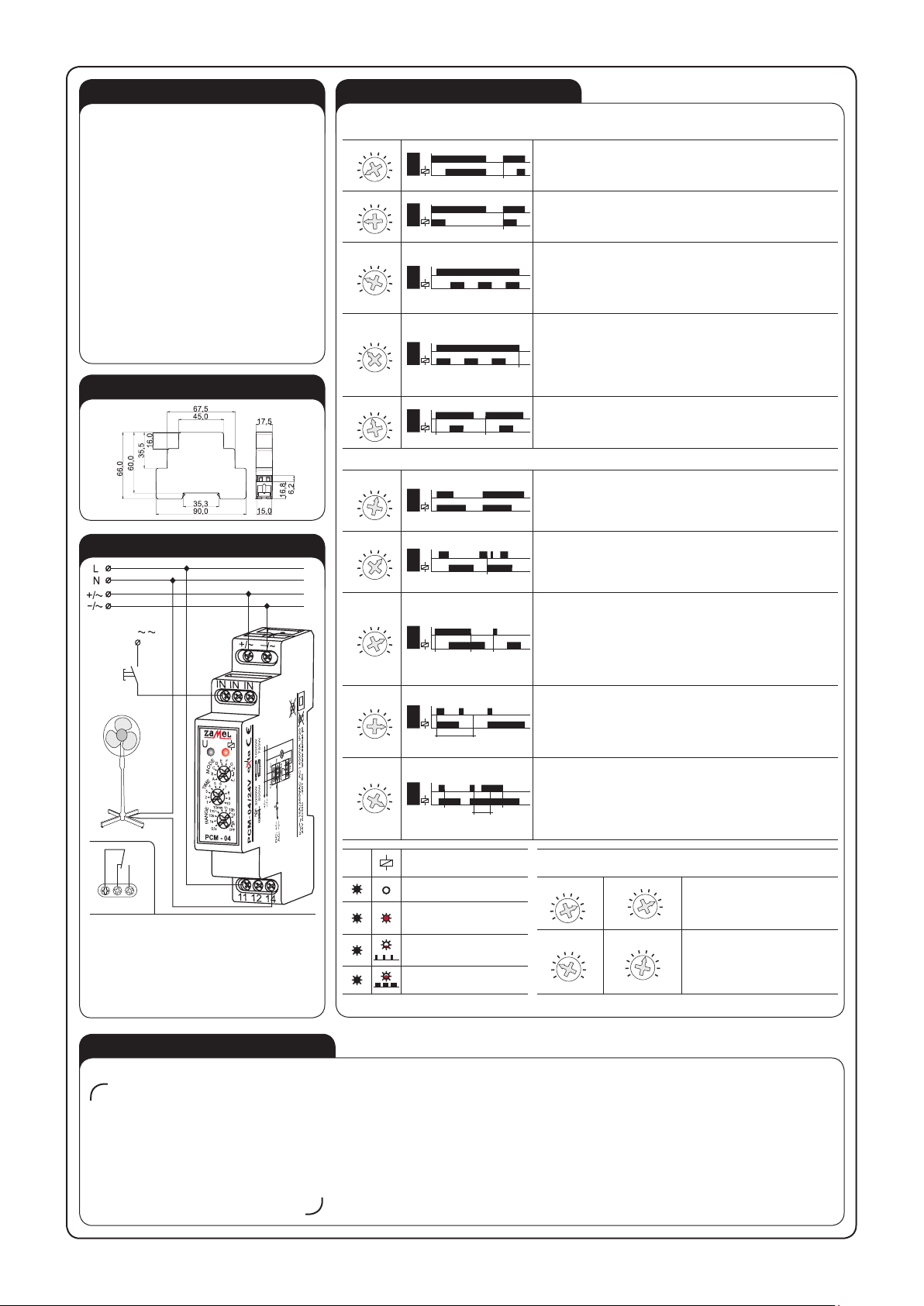
SWITCH ON DELAY - after the supply voltage [U] has been applied the
time measure t starts. After the time is over the relay switches on (pos.
11-14). The next switch on interval appears after power supply voltage
reset.
M
O
D
E
AJ
B
C
DEFG
H
I
U
t t
B
SWITCH OFF DELAY - after the supply voltage [U] has been applied, the
output relay [R] switches on immediately (pos.11-14), and the preset time
[t] is measured. After the preset time [t] has been measured, the output
relay [R] returns to the initial state (pos.11-12).
M
O
D
E
AJ
B
CDEFG
H
I
U
tt t ttt
C
FLASHER STARTING WITH OFF - (Starting from the switch off position).
After the supply voltage [U] has been applied, the preset time [t] measurement
starts. After the time [t] is over, the relay switches on (pos.11-14) and the pre-
set time [t] is measured once more. After the preset time [t] is over, the output
relay [R] returns to the initial state (pos.11-12), and the next operating cycle of
the relay starts. The relay operates until the supply voltage is removed.
M
O
D
E
AJ
B
C
DEFG
H
I
U
ttttt
D
t
FLASHER STARTING WITH ON - (Starting from the switch off position). After
the supply voltage [U] has been applied, the relay is switched on immediately
(pos.11-14) and the preset time [t] measurement starts. After the time [t] is
over, the relay switches off (pos.11-12) and the preset time [t] is measured
once more. After the preset time [t] is over, the output relay [R] returns to the
initial state, and the next operating cycle of the relay starts. The relay operates
until the supply voltage is removed.
AJ
B
C
DEFG
H
I
M
O
D
E
E
U
0.5s
t
0.5s
t
DELAY IMPULSE GENERATION 0,5 s - after the supply voltage [U] has
been applied the time measure t starts. After the time is over the relay swit-
ches on (pos. 11-14) for 0,5s, next the relay is switched off (pos.11-12). The
next switch on interval appears after power supply voltage reset.T.
External signal release:
AJ
B
C
DEFG
H
I
M
O
D
E
S
F
t t
GROWING MODULATED VOLTAGE VALUE – after the impulse release
has been applied to the powered system (growing value) it switches on
the relay (pos. 11-14), and starts to measure the preset time. After the
time t is over the relay switches off (pos.11-12). Impulse time duration is
not important here (pos.11-12).
AJ
B
C
DEFG
H
I
M
O
D
E
S
t t
G
FALLING MODULATED VOLTAGE VALUE - powered system switches
on the relay after impulse release fades (pos. 11-14) and time measu-
rement starts. The relay is switched off after time t is nished. The follo-
wing time release fades during time measurement does not cause time
measure from the beginning (no retriggerable).
AJ
B
C
DEFGH
I
M
O
D
E
S
tt
H
ttt
SWTCH ON/OFF DELAY - after the impulse release has been applied to
the powered system (growing value) let the relay be switched off (pos.11-
12), the same, starts the preset time t measurement. After the time is
over the relay is switched on (pos. 11-14). After the impulse release fade
is detected (falling modulated voltage), the system starts preset time me-
asurement again after it is nished the relay is switched off (pos.11-12).
In case impulse duration is longer than the preset time t the relay is
switched on for the t time only.
AJ
B
C
DEFG
H
I
M
O
D
E
S
tt
I
t
BISTABLE RELAY WITH TIME LIMIT - after the impulse release has been
applied to the powered system (growing value) it switches on the relay
(pos. 11-14), and starts to measure the preset time. The relay is switched
off during the next impulse release (growing modulated voltage) or after
time t is over if there was no such impulse occurence. Impulse time dura-
tion is not important for system operating.
AJ
B
C
DEFG
H
I
M
O
D
E
S
J
t tt t
t
GROWING MODULATED VOLTAGE VALUE WITH SWTCH OFF DELAY
(RETRIGGERABLE) - after the impulse release has been applied to the
powered system (growing value) it switches on the relay (pos. 11-14). After
the impulse release fade is detected (falling modulated voltage), the system
starts preset time measurement again and when it is nished the relay is
switched off (pos.11-12). In case impulse duration is longer than the preset
time t the relay is switched on for the t time only.
UDiodes’ function
description Time adjustment example t
☼Relay turned off
time not counted down
110
5678
9
2
3
4
T
I
M
E
0,1s OFF
1s
10s
1min
10min 1h 10h
1d
ON
R
A
N
G
E
t = TIMExRANGE,
t = 8 x 1 d = 8 d
☼ ☼ Relay turned on
time not counted down
T
I
M
E
110
567
8
9
2
34
0,1s OFF
1s
10s
1min
10min
1h
10h
1d
ON
R
A
N
G
E
t = TIMExRANGE,
t = 3 x 1 h = 3 h
☼☼Relay turned off
time counted down
☼☼Relay turned on
time counted down
DC: +/
-
AC: /

Other Zamel Relay manuals

Zamel exta PCM-09 User manual

Zamel

Zamel exta PCM-09 User manual

Zamel EXTA PBM-03 User manual

Zamel

Zamel EXTA PBM-03 User manual

Zamel PCM-08 User manual

Zamel

Zamel PCM-08 User manual

Zamel Exta PCM-02/U User manual

Zamel

Zamel Exta PCM-02/U User manual

Zamel exta PPM - 05 User manual

Zamel

Zamel exta PPM - 05 User manual

Zamel exta PCM-01 User manual

Zamel

Zamel exta PCM-01 User manual

Zamel EXTA PCM-11 User manual

Zamel

Zamel EXTA PCM-11 User manual

Zamel Exta PBM-07 User manual

Zamel

Zamel Exta PBM-07 User manual

Zamel EXT10000084 User manual

Zamel

Zamel EXT10000084 User manual

Zamel exta PBM-07 User manual

Zamel

Zamel exta PBM-07 User manual

Zamel Exta PBM-03 User manual

Zamel

Zamel Exta PBM-03 User manual

Zamel Exta PBM-04/U User manual

Zamel

Zamel Exta PBM-04/U User manual

Zamel exta PB Series User manual

Zamel

Zamel exta PB Series User manual

Zamel PCM-02/24V User manual

Zamel

Zamel PCM-02/24V User manual

Zamel EXTA PCP-04 User manual

Zamel

Zamel EXTA PCP-04 User manual

Zamel EXTA PBP-01 User manual

Zamel

Zamel EXTA PBP-01 User manual

Zamel PCM-07/U User manual

Zamel

Zamel PCM-07/U User manual

Zamel EXTA PCP-06 User manual

Zamel

Zamel EXTA PCP-06 User manual

Zamel PNM-32 User manual

Zamel

Zamel PNM-32 User manual

Zamel PNM-10 User manual

Zamel

Zamel PNM-10 User manual

Zamel exta PNM-10 User manual

Zamel

Zamel exta PNM-10 User manual

Zamel PBM-01 User manual

Zamel

Zamel PBM-01 User manual

Zamel EXTA PBM-02 User manual

Zamel

Zamel EXTA PBM-02 User manual

Popular Relay manuals by other brands

Steren K-415 user manual

Steren

Steren K-415 user manual

Eaton Cutler-Hammer D64RPB30 Series instructions

Eaton

Eaton Cutler-Hammer D64RPB30 Series instructions

Pilz PNOZ X3 20547-6NL-07 operating instructions

Pilz

Pilz PNOZ X3 20547-6NL-07 operating instructions

LinTronic 208 Operation manual

LinTronic

LinTronic 208 Operation manual

Xylem CentriPro 9K585 instruction manual

Xylem

Xylem CentriPro 9K585 instruction manual

Honeywell R182J manual

Honeywell

Honeywell R182J manual

OXO Simoun 2 R instruction manual

OXO

OXO Simoun 2 R instruction manual

Schweitzer Engineering Laboratories SEL-700G Series instruction manual

Schweitzer Engineering Laboratories

Schweitzer Engineering Laboratories SEL-700G Series instruction manual

Toshiba GRL100-101A instruction manual

Toshiba

Toshiba GRL100-101A instruction manual

Bender IOM441-S manual

Bender

Bender IOM441-S manual

Mauell MR 10 manual

Mauell

Mauell MR 10 manual

Rockwell Automation Allen-Bradley E3 quick start guide

Rockwell Automation

Rockwell Automation Allen-Bradley E3 quick start guide

TE Connectivity SRS4M-2NO quick start guide

TE Connectivity

TE Connectivity SRS4M-2NO quick start guide

Eaton ESR5-NO-21-24VDC manual

Eaton

Eaton ESR5-NO-21-24VDC manual

Siemens Argus 7SR21 installation guide

Siemens

Siemens Argus 7SR21 installation guide

Weatherdock ME SENSE RELAY WiFi instruction manual

Weatherdock

Weatherdock ME SENSE RELAY WiFi instruction manual

Omron K8AB-AS manual

Omron

Omron K8AB-AS manual

Bticino 3584C quick start guide

Bticino

Bticino 3584C quick start guide

manuals.online logo
manuals.online logoBrands
  • About & Mission
  • Contact us
  • Privacy Policy
  • Terms and Conditions

Copyright 2025 Manuals.Online. All Rights Reserved.