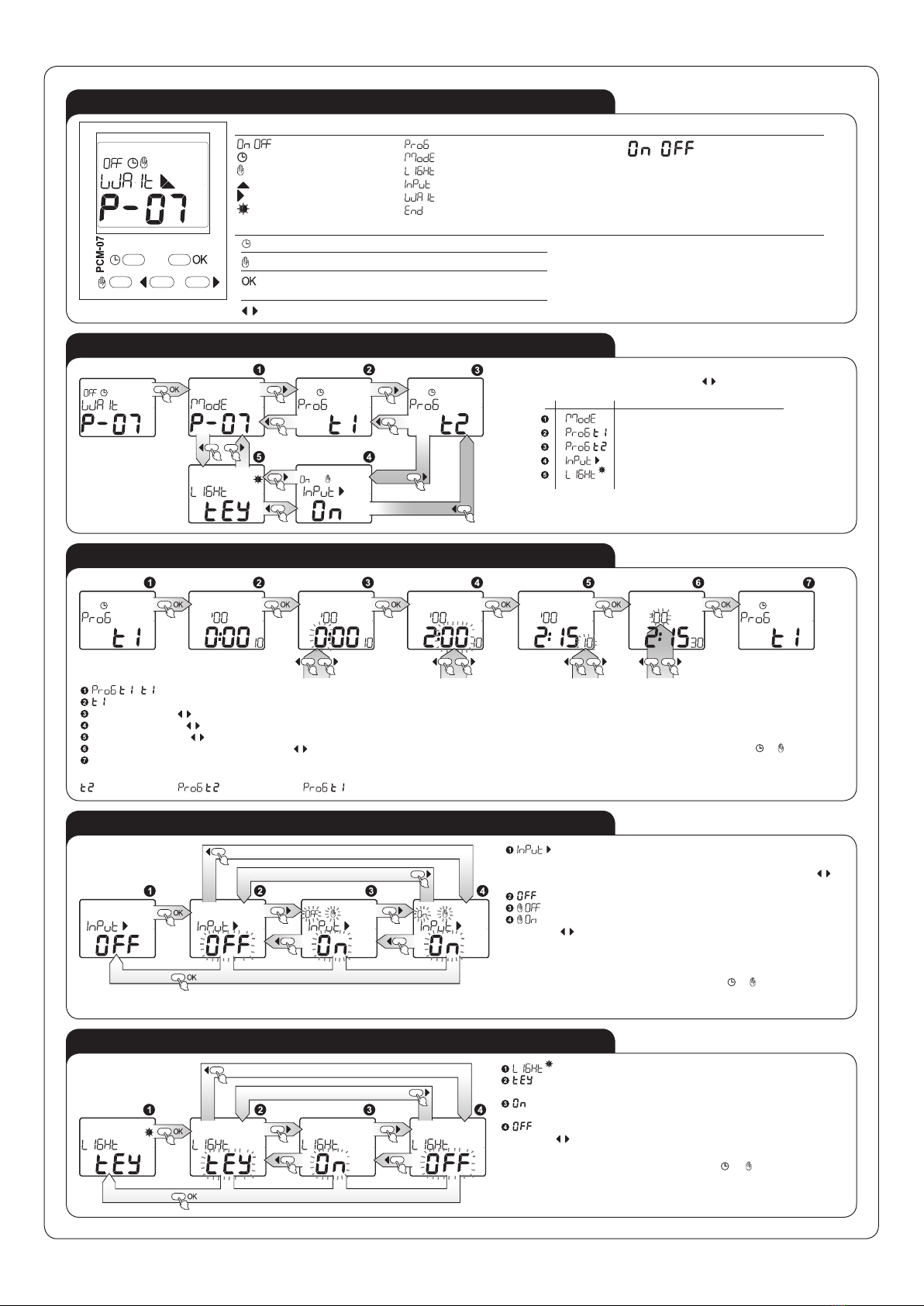
OPERATING MODE ADJUSTMENT
- operating mode adjustment will be activated in the moment of releasing external
input S; press OK to enter;
Use cursors to choose the right mode; the modes are numbered in the range from
to , press OK to conrm your choice;
Conrming the command allows to enter the operating mode adjustment window.
There is an escape possibility from every submenu window one level higher in every moment of
programming by pressing or without saving the adjusments.
Power supply voltage release:for for and
SWITCH ON DELAY - after the supply voltage has been
applied the preset time t measure starts. After the time is
over the relay switches on (pos. 11-14). The next switch
on mode appears after power supply voltage reset.
SWITCH ON DELAY - after the supply voltage has been
applied the t1 time measure starts. After the time is over
the relay switches on (pos. 11-14) for t2 time. The next
switch on interval appears after power supply voltage
reset.
SWITCH OFF DELAY - after the supply voltage has been
applied, the relay switches on immediately (pos.11-14),
and the preset time t is measured. After the preset time
is measured, the relay is switched off (pos.11-12). The next switch on interval appears after power
supply voltage reset.
SWITCH OFF DELAY - after the supply voltage has
been applied, the output relay switches on immediately
(pos.11-14), and the preset time t1 is measured. After the
preset time is measured, the relay is switched off (pos.11-
12) for the preset t2 time and its another switch on mode. The next switch on interval appears after
power supply voltage reset.
FLASHER STARTING WITH OFF – (Starting from the
switch off position). After the supply voltage has been
applied, the preset time t is measured. After the time is
over, the relay switches on (pos. 11-14). Again with the preset time t interval, the relay is switched
off (pos.11-12) and switched on (pos. 11-14). The next switch on interval appears after power supply
voltage reset.
FLASHER STARTING WITH OFF – (Starting from the
switch off position). After the supply voltage has been
applied, the preset time t1 is measured. After the time is
over, the relay switches on (pos. 11-14) for the preset t2 time and again switches off (pos.11-12) for the
preset t1 time. The next switch on interval appears after power supply voltage reset.
FLASHER STARTING WITH ON – (Starting from the
switch on position). After the supply voltage has been
applied, the relay is immidiatelly switched on (pos. 11-14)
and the preset time t is measured. After the time t is over, the relay switches off (pos. 11-12). Again
with the preset time t interval the relay is switched on (pos. 11-14) and switched off (pos. 11-12). The
next switch on interval appears after power supply voltage reset.
FLASHER STARTING WITH OFF – (Starting from the
switch on position). After the supply voltage has been ap-
plied, the output relay switches on immediately (pos.11-
14) for the preset time t1. After the time is over, the relay is swtches off (pos.11-12) for the preset
t2 time and its another switch on mode for t1 time. The next switch on interval appears after power
supply voltage reset.
IMPULSE GENERATOR DELAY 0,5 sec. - After the sup-
ply voltage has been applied the preset time t measure
starts. After the time t is over the relay switches on (pos.
11-14) for 0,5 second, and switches off (pos. 11-12). The
next switch on interval appears after power supply voltage reset.
PERMANENT SWITCH ON MODE - After the supply vol-
tage has been applied the relay is switched on permanen-
tly. When choosing this mode t1 and t2 time adjustments
do not matter.
PERMANENT SWITCH OFF MODE - After the supply
voltage has been applied the relay is switched off per-
manently. When choosing this mode t1 and t2 time adjust-
ments do not matter.
TIME IMPULSE RELEASED BY RISING EDGE – after
the impulse release has been applied to the power-supply
system (rising edge) it switches on the relay (pos. 11-14)
and starts to measure the preset time. After the time t is over the relay is switched off (pos. 11-12).
Impulse time duration is not important here.
SWITCH ON/OFF DELAY- (retriggerable) – after the im-
pulse release has been applied to the power-supply sys-
tem (rising edge), it lets the relay be switched off (pos.
11-12) and at the same time, starts the preset time t1 measurement. After the time is over the relay
is switched on (po. 11-14). After the impulse release fade is detected (falling modulated voltage), the
system starts preset t2 time measuremnt and after it is over the relay is switched off (po. 11-12). In case
the impulse release duration is shorter than the preset time t1, the relay is not switched on. Applying
the impluse release during the preset t2 time measurement does not cause switching off the relay but
it starts time measurement after the impulse fade (falling modulated voltage).
TIME IMPULSE RELEASED BY FALLING EDGE – po-
wer-supply system switches on the relay after impulse
release fades (falling edge) (pos.11-14) and time measu-
rement starts. After the time t is over the relay is switched off (pos. 11-12). The following impulse
release fades during time measurement does not cause time measure from the beginning (non- re-
triggerable).
SWITCH ON/OFF DELAY- (non-retriggerable) – after the
impulse release has been applied to the power-supply
system (rising edge), it lets the relay be switched off (pos.
11-12), at the same time, starts the preset time t1 measurement. After the time is over the relay is swit-
ched on (pos. 11-14). After the impulse release fade is detected (falling modulated voltage), the system
starts preset time t2 measuremnt and after it is over the relay is switched off (po. 11-12).The release
input state can change during the time t2 measurement and does not affect functioning of the system In
case the impulse release duration is shorter than the preset time t1, the relay is not switched on.
SWITCH ON/OFF DELAY – after the impulse release has
been applied to the power-supply system (rising edge),it
lets the relay be switched off (pos.11-12) and at the same
time starts the preset time t measurement. After the time is over the relay is switched on (pos.11-14).
After the impulse release fade is detected (falling edge), again the system starts the preset time me-
asurement. When it is over the relay is switched off (pos. 11-12). In case the impulse duration time is
shorter than the preset time t, the relay is switched on only for the time t.
IMPULSE GENERATION WITH AN ALTERNATE TIME
DURATION - after the impulse release has been applied
to the power-supply system (growing value), it switches
on the relay for the preset time t1, and switches it off. The next impulse release causes the relay swit-
ches on for t2 time. Another one switches on the relay for t1 time, etc. The impulse release time duration
does not inuence the relay switching on time.
BISTABLE RELAY WITH TIME LIMIT – after the impulse
release has been applied to the power-supply system (ri-
sing edge), it switches on the relay (pos.11-14) and starts
to measure the preset time t. The relay is switched off
during the next impulse release (rising edge) or after time t is over in case there was no such impulse
occurence. Impulse time duration is not important for system operating.
SWITCH OFF DELAY RELEASED BY FALLING EDGE
- after the impulse release has been applied to the po-
wer-supply system, it switches on the relay (pos. 11-14).
Impulse release fade causes the preset time t1 measurement, after it is over the relay is switched off
(po. 11-12) for the preset time t2. During the t2 time the system is resistant to signals release. After
the t2 time is over the relay is switched on again in the moment of applying impulse release (growing
value).
TIME IMPULSE RELEASED BY RISING EDGE WITH
SWITCH OFF DELAY (non-retriggerable) - after the
impulse release has been applied to he power-supply
system (rising edge) it switches on the relay (pos.11-14).
After the impulse release fade is detected (falling modulated voltage), the system starts the preset time
t measurement and when the time is over the relay is switched off (pos. 11-12).
IMPULSE RELEASED BY FALLING EDGE - after the
impulse release has been applied to the power-supply
system (rising edge), it switches on the relay for the pre-
set time t1, and after the time elapses it switches off the relay. The impulse release fade (falling edge)
switches on the relay (pos. 11-14) for the preset time t2, and after the time elapses it switches it off.
During switching on the relay the rising edge and the falling edge are ignored.
SWITCH ON DELAY RELEASED BY IMPULSE - after
the impulse release has been applied to the power-supply
system (rising edge) it keeps the relay in a switched off
position (pos.11-12) and simultaneously starts the preset
time t measurement. After the time t is over the relay is
switched on (pos. 11-14). The relay is switched on as long as there is a power supply voltage on, the
next release impulses do not affect operation of the relay.
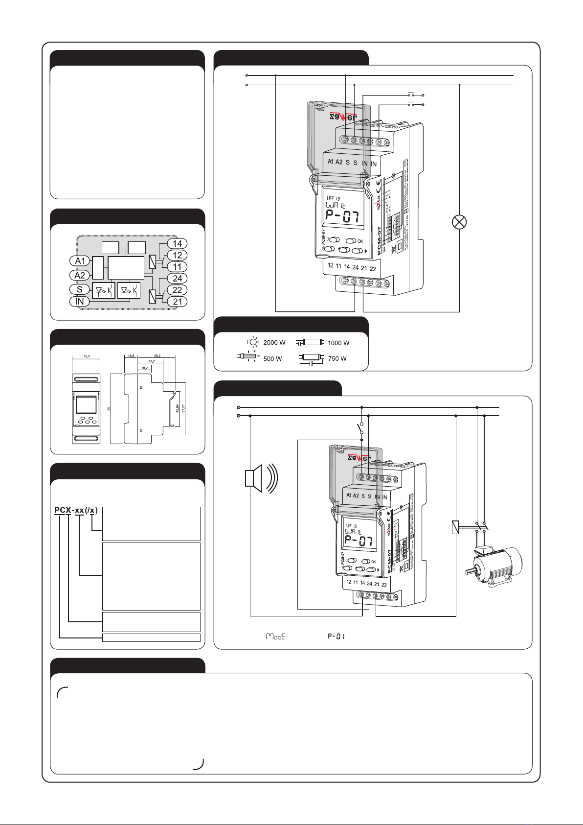
STAR-DELTA SWITCH - after the supply voltage has
been applied the relay 1 is switched on (pos. 11-14) for
the preset time t1. After the time is over the relay is swit-
ched off and the preset time t2 is measured. After time
t2 is over the relay 2 is switched on permanently (pos.
21-24).
U
11-14
21-24
t1
t2 t
External signal S release:for for and
TIME IMPULSE RELEASED BY RISING EDGE WITH
SWITCH OFF DELAY (retriggerable) - after the impulse
release has been applied to the power-supply system (ri-
sing edge) it switches on the relay (pos.11-14). After the
impulse release fade is detected (rising edge), the system starts the preset time t measurement and
when the time is over the relay is switched off (pos. 11-12). The following impulse release fade during
time measurement causes time measure from the beginning (retriggerable).
TIME IMPULSE RELEASED BY IMPULSE WITH SPE-
CIFIC TIME DURATION - after the impulse release has
been applied and lasts continuously for the preset time
t1, it switches on the relay (pos.11-14) for time t2. If the
release impulse is shorter than the preset time t1, the relay is not switched on - during switching on the
relay the releasing impulses are ignored.
S
t1 t1t2 t2
11-14
S
U
t
11-14
S
t t
11-14
S
t tt t
t
11-14
S
tt
t
11-14
S
ttttt
11-14
S
t t
11-14
S
t t
11-14
U
0.5s
t
0.5s
t
11-14
U
tttttt
11-14
U
tt t ttt
11-14
U
t t
11-14
U
tt
11-14
S
t1 t1 t2
11-14
S
tt1 t2 t t1
11-14
S
t1 t2 t1
11-14
S
t1 t1 t2
11-14
S
t1 t1 t2
11-14
U
11-14
U
11-14
U
t1 t2t1 t2t2 t1
11-14
U
t2 t1 t2 t1 t2t1
11-14
U
t1 t2 t2
t1
11-14
U
t2 t1t1 t2
11-14