PBM - 03 BISTABLE RELAY INSTRUCTION MANUAL
Zakład Mechaniki i Elektroniki
ZAMEL sp.j.
J.W. Dzida, K. Łodzińska
ul. Zielona 27, 43-200 Pszczyna, Poland
Tel. +48 (32) 210 46 65, Fax +48 (32) 210 80 04
FEATURES
TECHNICAL DATA
DESCRIPTION
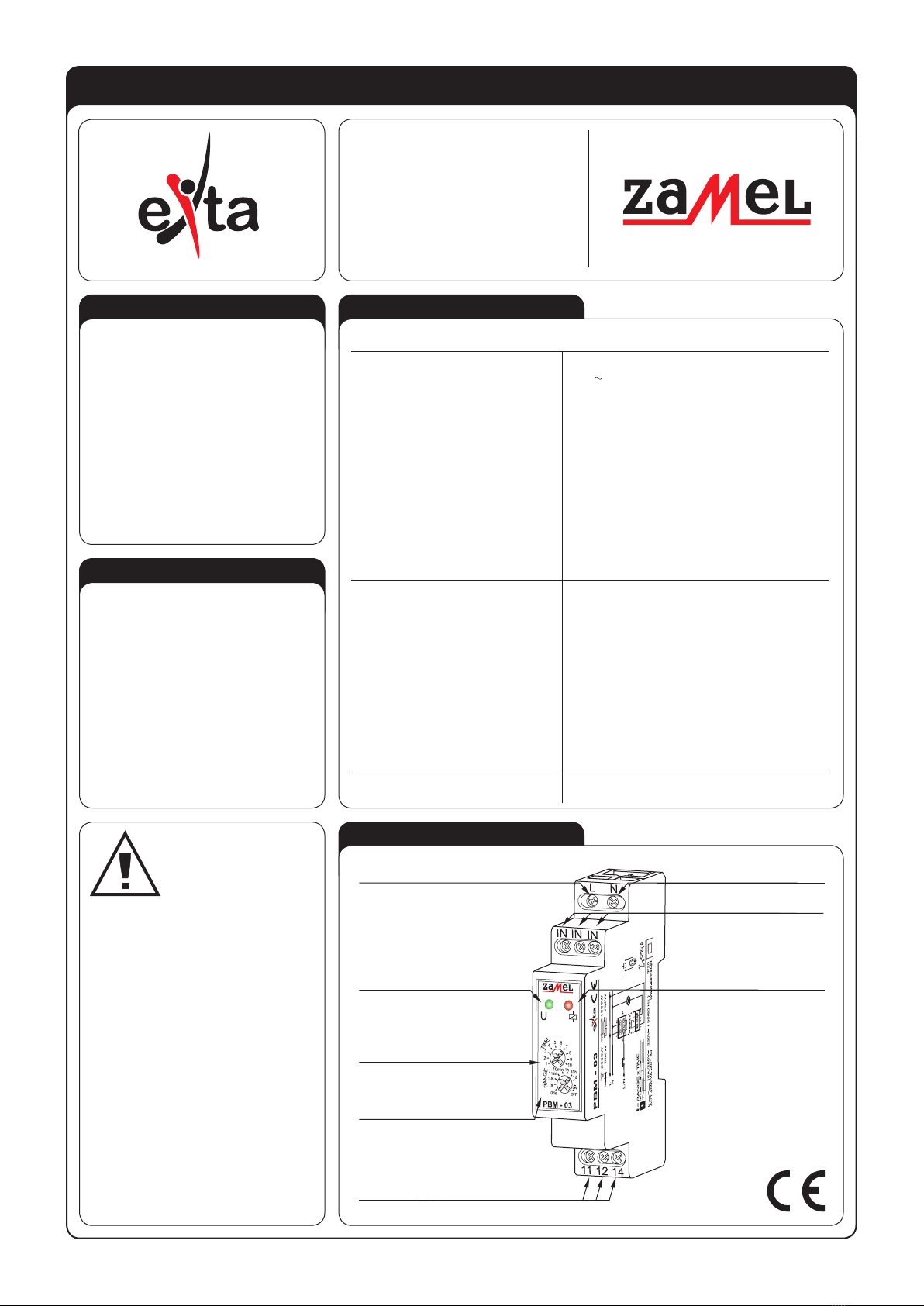
APPERANCE
PBM - 03
Power terminals: L, N
Rated voltage: 230 V
Rated voltage tolerance: -15 ÷ +10 %
Rated frequency: 50 / 60 Hz
Rated current: 24 mA
t time adjustment range:
0,1 s
÷ 10 dni
Time measure accuracy:
0,2 %
Time setting:
2 x potentiometer (rotary + servo)
Supply voltage indicator:
green LED
Trigger terminals / wires: IN, IN, IN
Trigger circuit control current: 510 µA
Relay state indicator: red LED
Relay contacts parameters:
1NO-16 A / 250 V AC1 4000 VA
Connection wires quantity: 8
Connection wire section: 0,2 ÷ 2,50 mm2
Operating temperature: -20 ÷ +45 oC
Operating position: optional
Casing fastening: TH 35 rail (according to PN-EN 60715)
Casing IP: IP20 (PN-EN 60529)
Protection class: II
Overvoltage category: II
Pollution level: 2
Dimensions: single-module (17,5 mm) 90x17,5x66 mm
Weight: 75 g
Standard conformity: PN-EN 60669-1, PN-EN 60669-2-1,
PN-EN 61000-4-2,3,4,5,6,11
ی Bistable lighting control,
ی Time limit function,
ی Power supply indicator - red LED,
ی Relay state indicator - red LED,
ی Device triggering by means either of
the L or N wire,
ی Operation with many single pole push
buttons, illuminated,
ی Time limit function,
ی Two-conductor control system,
ی Relay voltage output, maximum 16 A
load,
ی Single-module casing.
The PBM-03 bistable relay is designed for
lighting and other device control by means
of single pole push buttons connected in
parallel. Successive pressing of any button
causes switching ON / OFF the load alter-
natively. Either L or N line may be a source
of a control impulse. After the impulse has
arrived the load is ON. Then, after t preset
time has been over the load is OFF. It is
possible to create lighting control intelligent
systems by means of using the PBM-03
modules..
Relayoutput
Supplyvoltage indicator
Power terminal (N)
Powerterminal(L)
C
o
n
t
i
n
u
o
u
s
t
i
m
e
Relaystate indicator
(time measure signalling)
terminals (11, 12, 14)
Time range
selection
adjustment
Trigger terminals
(IN, IN, IN)
The timer should be
connected to a single-
phase system accordin-
gly to current standards.
The device connections
will be described in this
manual. Only qualied electricians are
allowed to assembly, connect and ad-
just the timer. It is necessary to read this
manual before the timer mounting. Do
not disassembly the timer casing or you
will lose any warranty rights and expo-
se yourself to the electric shock hazard.
Before mounting operation make sure
of disconnecting the connection wires
from the electric network. The timer
should be carried, stored and used in
an appropriate way. Do not mount the
timer in case of any device parts lack,
damage or deformation. In case of mal-
function please notify the manufacturer.
CAUTION


