manuals.online logo
Brands
  1. Home
  2. •
  3. Brands
  4. •
  5. Zamel
  6. •
  7. Relay
  8. •
  9. Zamel exta PNM-10 User manual

Zamel exta PNM-10 User manual

VOLTAGE RELAY PNM-10 USER’S MANUAL
ZAMEL sp. z o.o.
ul. Zielona 27, 43-200 Pszczyna, Poland
Tel. +48 (32) 210 46 65, Fax +48 (32) 210 80 04
www.zamel.com, e-mail: [email protected]
plik: pnm-10_inst_ext_gb | modykacja: 23.09.2020
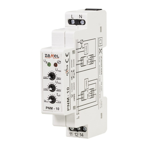
APPEARANCE
FEATURES
TECHNICAL DATA
DESCRIPTION
PNM - 10
Power supply terminals: L, N
Rated supply voltage: 230 V AC
Tolerance of supply voltage: from -15 to +10 %
Nominal frequency: 50 / 60 Hz
Rated power consumption: 35 mA
Voltage value control indicator: green LED
Power/relay supply indicator and “soft net”: red LED
Voltage threshold adjustment: 2x rotary potentiometer
Voltage threshold adjustment range Umin: from 170 to 225 V
Voltage threshold adjustment range Umax:from 235 to 290 V
Switch off time adjustment toff: from 0 to 12 s rotary potentiometer
Time/Voltage measure accuracy: ±1,5 / ±5 %
Switch off time after “soft net” detection: 10 min (LED red pulses)
Output relay parameters: 1NO/NC - 10 A / 250 V AC1 2500 VA
Number of terminal clamps: 5
Section of connecting cables: from 0,2 to 2,50 mm2
Ambient temperature range: from -20 to +60 oC
Operating position: free
Mounting: TH35 rail (PN-EN 60715)
Protection degree: IP20 (PN-EN 60529)
Overvoltage category: II
Pollution degree: 2
Rated impulse withstand voltage: 2 kV (PN-EN 61000-4-5)
Dimensions (height / width / depth): single-module (17,5 mm) 90x17,5x66 mm
Weight: 0,07 kg
● It is used to protect one phase output
(load) from voltage drop,
● voltage value control indicator,
● power/relay supply indicator,
● minimum value adjustment
(170 ÷ 225 V) and maximum
(235 ÷ 290 V) voltage,
● switch off time delay adjustment
(0 ÷ 12 seconds),
● “soft net” effect detection,
● voltage relay output - 1 change over
contact (NO/NC) max 10 A capacity,
● monomodular casing,
● TH-35 DIN rail installation.
PNM-10 voltage relays is used for
control of voltage values in the single-
phase networks to protected the receiver
against increase or decrease of voltage
outside the set values: minimum and
maximum. The relay is equipped with
switching off time regulation. The sys-
tem detects a so-called effect of “soft
net” switching the receiver off for 10 min-
utes.
The device should be con-
nected to a one-phase network
in accordance with legally bind-
ing standards. The connection
method is described in this man-
ual. Any activities related to in-
stallation, connection, and adjustment should
be performed by qualied electricians who
have read this user’s manual and familiarised
themselves with device functions. Removing
the enclosure voids the warranty and poses
a risk of electric shock. Before installation,
make sure that there is no voltage on connec-
tion cables. To install the device, use a cross-
head screwdriver with a diameter of 3.5 mm.
The proper operation of the device is affected
by how the device is transported, stored, and
used. It is not advisable to install the device in
the following cases: lack of any components,
damage to or deformation of the device. If the
device operates improperly, please contact
the manufacturer.
NOTE
Do not dispose of this device together
with other waste! To avoid harmful effects
on the environment and human health,
the worn-out device should be stored
in designated areas. Electrical waste
from households may be handed over
to the waste collector established for
this purpose free of change and in any
amount, as well as to the store when
purchasing new equipment.
Power supply terminals (L, N)
Voltage value control indicator Power/relay supply indicator
“soft net” effect
Maximum voltage value adjustment
Minimum voltage value adjustment
Switch off delay time threshold
Output terminals (11, 12, 14)
MOUNTING CONNECTING
DIMENSIONS
PRODUCT FAMILY LED MODE TIME COURSE
UP Mode
☼☼☼☼Voltage in the adjusted time,
relay switched on.
☼☼○Voltage higher than Umax,
relay switched off.
☼☼○Voltage lower than Umin,
relay switched off.
☼☼☼☼“Soft net” effect detected.
1. Disconnect the power supply from the
mains by the phase fuse, the circuit-
breaker or the switch-disconnector
that are joined to the proper circuit,
2. Check if there is no voltage on con-
nection cables by means of a spe-
cial measure equipment,
3. Install PNM-10 device in the switch-
board on TH-35 DIN rail,
4. Connect the cables with the terminals
according to installing diagram,
5. Switch on the power supply from the
mains,
6. Adjust the required voltage value
Umax and Umin and time delay
switch off toff.
EXAMPLE OF INSTALLATION
PNM-10 voltage relay belongs to PNM
voltage relay product family.
RELAY CAPACITY
INNER DIAGRAM
FUNCTIONING
After the relay has been switched on
it controls the voltage value on its supply
terminals. In case the voltage is above the
<Umin, Umax> level, toff time is meas-
ured. The relay is switched off if the volt-
age is not equal with the preset voltage
value. The relay is not switched off in
case voltage value is lower than toff time.
Another relay switch on occurs when the
voltage value is equal with the preset volt-
age value (taking into account the hyster-
esis about 3 V). The system protects the
load capacity from the “soft net” effect that
occurs in a situation when the connected
load causes voltage drop below Umin.
In case there are three switch off effects
the output access is cut for about 10 min-
utes (red LED diode pulses). The green
LED diode is switched on when there is a
proper voltage value, in the range <Umin,
Umax>. The green LED pulses rapidly,
when voltage is higher than Umax or it
pulses slowly when voltage is lower than
Umin.
PNM-10 voltage relay cooperates with
the LDM-10 voltage indicator. The value
of voltage in a single-phase network is
measured in the circuit of the relay whose
outputs cut off the power supply to the pro-
tected circuit (e.g. motor) if the set voltage
range has been exceeded. Voltage indica-
tor allows ongoing visualisation of value of
voltage supplying the protected circuit.
300 W
1250 W 600 W
450 W
Device version:
10 – single phase
31 – three-phase
32 – three-phase, LCD
Device type
WARRANTY CARD
Manufacturer provides a 24-month warranty
Seller’s stamp and signature, date of sale
1. ZAMEL Sp. z o.o. shall offer a 24-month warranty on the products sold.
2. The warranty provided by ZAMEL Sp. z o.o. shall not cover:
a) mechanical damage caused during transport, loading/unloading or in other circumstances,
b) damage caused by incorrect installation or operation of products manufactured by ZAMEL Sp. z o.o.,
c) damage resulting from any changes made by the BUYER or third parties in the products sold or equipment necessary for the
proper operation of the products sold,
d) damage resulting from force majeure or other fortuitous events for which ZAMEL Sp. z o.o. is not liable.
3. Any warranty claims shall be made by the BUYER at the point of sale or to ZAMEL z o.o. in writing after defects have been identi-
ed.
4. ZAMEL Sp. z o.o. undertakes to handle complaints in accordance with the applicable provisions of Polish law.
5. The choice of the form of complain resolution, e.g. replacement of a product with a product free from defects, repair, or reimburse-
ment of money, shall lie with ZAMEL Sp. z o.o.
6. The warranty does not exclude, limit, or suspend BUYER’s rights under the statutory warranty for defects in the item sold.
:RobertRoszkowski
e-mail:senseir@wp.pl
TV
owski
e-mail:senseir@wp.pl

This manual suits for next models

1

Other Zamel Relay manuals

Zamel PNM-32 User manual

Zamel

Zamel PNM-32 User manual

Zamel PCM-04/24V User manual

Zamel

Zamel PCM-04/24V User manual

Zamel Exta PBM-07 User manual

Zamel

Zamel Exta PBM-07 User manual

Zamel EXTA PBM-03 User manual

Zamel

Zamel EXTA PBM-03 User manual

Zamel PCM-08 User manual

Zamel

Zamel PCM-08 User manual

Zamel Exta PCM-02/U User manual

Zamel

Zamel Exta PCM-02/U User manual

Zamel EXT10000084 User manual

Zamel

Zamel EXT10000084 User manual

Zamel exta PCM-09 User manual

Zamel

Zamel exta PCM-09 User manual

Zamel Exta PBM-04/U User manual

Zamel

Zamel Exta PBM-04/U User manual

Zamel exta PPM - 05 User manual

Zamel

Zamel exta PPM - 05 User manual

Zamel PBM-01 User manual

Zamel

Zamel PBM-01 User manual

Zamel EXTA PCP-04 User manual

Zamel

Zamel EXTA PCP-04 User manual

Zamel EXTA PCP-06 User manual

Zamel

Zamel EXTA PCP-06 User manual

Zamel EXTA PBM-02 User manual

Zamel

Zamel EXTA PBM-02 User manual

Zamel Exta PBM-03 User manual

Zamel

Zamel Exta PBM-03 User manual

Zamel PCM-07/U User manual

Zamel

Zamel PCM-07/U User manual

Zamel PCM-02/24V User manual

Zamel

Zamel PCM-02/24V User manual

Zamel exta PBM-07 User manual

Zamel

Zamel exta PBM-07 User manual

Zamel exta PCM-01 User manual

Zamel

Zamel exta PCM-01 User manual

Zamel EXTA PBP-01 User manual

Zamel

Zamel EXTA PBP-01 User manual

Zamel EXTA PCM-11 User manual

Zamel

Zamel EXTA PCM-11 User manual

Zamel exta PB Series User manual

Zamel

Zamel exta PB Series User manual

Zamel PNM-10 User manual

Zamel

Zamel PNM-10 User manual

Popular Relay manuals by other brands

Pilz PNOZ s9 operating manual

Pilz

Pilz PNOZ s9 operating manual

Pilz PNOZ X2.1VP operating manual

Pilz

Pilz PNOZ X2.1VP operating manual

Pilz PMUT X1P operating manual

Pilz

Pilz PMUT X1P operating manual

Siemens SIRIUS 3RB3.3 Series manual

Siemens

Siemens SIRIUS 3RB3.3 Series manual

Contrel ELRC-B user manual

Contrel

Contrel ELRC-B user manual

Siemens SIRIUS 3RS1000 operating instructions

Siemens

Siemens SIRIUS 3RS1000 operating instructions

Basler BE1-50/51B-217 instruction manual

Basler

Basler BE1-50/51B-217 instruction manual

Viessmann 5552 Operation manual

Viessmann

Viessmann 5552 Operation manual

Nexa LCMR-1000 user manual

Nexa

Nexa LCMR-1000 user manual

ABB RELION REF615R Engineering manual

ABB

ABB RELION REF615R Engineering manual

Seg XRI1-IE manual

Seg

Seg XRI1-IE manual

Pilz PNOZ s1 operating manual

Pilz

Pilz PNOZ s1 operating manual

Siemens SIRIUS 3TK2841 operating instructions

Siemens

Siemens SIRIUS 3TK2841 operating instructions

Pilz PNOZ pe2p operating manual

Pilz

Pilz PNOZ pe2p operating manual

DMX SOUNDLIGHT 5202R-EP operating manual

DMX

DMX SOUNDLIGHT 5202R-EP operating manual

Basler BE1-51/27R instruction manual

Basler

Basler BE1-51/27R instruction manual

Pilz 20407-6NL-06 operating instructions

Pilz

Pilz 20407-6NL-06 operating instructions

GE IAV51A instructions

GE

GE IAV51A instructions

manuals.online logo
manuals.online logoBrands
  • About & Mission
  • Contact us
  • Privacy Policy
  • Terms and Conditions

Copyright 2025 Manuals.Online. All Rights Reserved.