Zummo Z05 Owner's manual

011302/01 1
Z05 (ZUMMITO) TECHNICAL INSTRUCTIONS
CONTENTS:
1.- Checking if cleaning and greasing is needed
2.- Opening the machine.
3.- Replacing the electronic circuit board.
4.- Replacing the pusher assembly.
5.- Replacing the bridge.
6.- Replacing a runner or a cup spring.
7.- Replacing a rod.
8.- Replacing a reducer.
9.- Changing the motor or the belt.
10.- Setting the cup stopping position.
11.- Belt changing (machines with shock absorbers on the motor mount).
12.- Closing the machine.
13.- Unlocking the selector
14.- Wiring diagrams
1. – CHECKING IF CLEANING AND GREASING IS NEEDED.
•With the cups in a vertical position, turn the machine over using the Allen key,
turning in a clockwise direction (reverse) (or manually in older machines) until the
cups are in the horizontal position. The machine can also be started and stopped
when the cups are rising (N.B. ensure that it is not when the cups are
descending).
1a 1b 1c
In this position move the cups upwards by hand and release them (Fig 1b). They
should return easily to their initial position, without needing to be assisted.
•Move the blade shaft up and down. It should descend under its own weight.
•Examine the feed paddle rod - it should be lightly greased. Apply a small quantity
of grease if necessary. (Fig. 1c)
2.- OPENING THE MACHINE.
•Disconnect the appliance from the mains power supply.
•Remove all the external parts (Fig. 2a).
•Remove the bolts from the top and the feed paddle, and the four from the base.
•Loosen the four mounts by 2 to 3mm.

011302/01 2
•Extract the front of the machine (Fig. 2b).
•Extract the rear (Fig. 2c)
•Disconnect the wires from the switch and the mains power supply (Fig. 2d)
except the mains supply bridge (Fig. 2e)
•Extract the electronic circuit board (2.5mm Allen key) (Fig. 2f)
2a 2b 2c
2d 2e 2f
3.- REPLACING THE ELECTRONIC CIRCUIT BOARD.
•Mark the wires in pairs before dismantling (Figs. 3a and 3b)
•Do not dismantle the board further. Send it to be repaired as it is. (Figs. 3c and
3d)
3a 3b
3c 3d

011302/01 3
4.- REPLACING THE PUSHER ASSEMBLY.
•Extract the key from the blade shaft (Figs. 4a and 4b).
•Dismantle the three runner covers in order to work safely.
•Extract the top bolt from the bridge (M8x50 Allen) and the top pin (Fig. 4c).
•Extract the pusher assembly (Fig. 4d).
4a 4b 4c
4d 5a 5b
5.- REPLACING THE BRIDGE.
•Repeat Section 4 without needing to extract the pusher assembly.
•Extract the bottom bolt from the bridge runner (M8x35Allen) (Fig.5a). This will
release the bridge.
•On fitting the new bridge, fit the rod in the highest position and the cups in the
vertical position (Fig. 5b).
6.- REPLACING A RUNNER OR A CUP SPRING.
DISMANTLING
•Carry out Step 4.
•Dismantling the micro strip (Fig 6a).
•Dismantle the top bar (Fig. 6b).
•Dismantle the short micrometer (Fig. 6c)
6a 6b 6c
•Dismantle the two cogs. (Fig. 6d).

011302/01 4
•Unscrew the bottom nut from the puller. An open-ended wrench will be required
(Figs 6e and 6f).
6d 6e 6f
•Extract the runner with its spring and puller (Fig. 6g).
ASSEMBLY
•Screw the nut onto the puller, fit the washer and screw the puller onto the runner.
There should be 210 -211mm free after the nut (Figs. 6h - i - j - k)
6g 6h 6i
6j 6k 6l
•Make sure that the puller is as perpendicular to the runner as possible.
•Grease the puller, fit the spring and grease it (Figs. 6l and 6m).
•Grease the operating area (Fig. 6n).

011302/01 5
6m 6n
•Fit the runner onto the guide and then fit into position, in this order:
1st Rubber washer. 2nd Flat washer. 3rd Locknut. (Fig. 6ñ)
•Complete the adjustment by adjusting the runner to 33.4mm using the nut on the
bottom brake (Fig. 6o).
•Close the chassis with the top flange without tightening the bolts.
•Fit the bridge with only the bottom bolt, without tightening it.
•Apply a little thread-locking adhesive (e.g. Loctite 648) “only on the M88x35 bolt”
(Fig. 6p).
6ñ6o 6p
•Place the rod in the highest position and fit the pin and the pusher assembly
(Figs. 6q and 6r). Tighten the two bolts.
•Grease the middle area of the cup shafts (Fig. 6s)
6q 6r 6s
•With the rod completely vertical (Fig. 6r) fit the cup shafts, fit the keys (Fig. 6t)
and the cogs, in such a way that in this position the cups have to be vertical (Fig.
6u). Fit the washers and tighten the bolts.

011302/01 6
6t 6u 6v
•Turn the motor by hand and fit the rod and the cups in position (Figs. 6v and 6w)
•Raise the cups by hand to the vertical position and release them (Fig. 6x) in
order to check if the runners work smoothly or stiffly.
6w 6x 6y
If they are excessively slack and there is play visible
between the cogs and the bridge, the guides should be
closed using a clamp (Fig 6y).
•If they are stiff, they should be opened up using a
lever (Fig 6z).
•Tighten the bolts and then re-check for slackness or
tightness (Fig. 6x).
•In this position, test the raising and lowering of the
blade mount assembly, and depending on the action,
action, open or close the central bars to achieve the
correct sliding fit. 6z
7. - REPLACING A ROD.
DISMANTLING
•Situate the rod at its top position.
•Remove the bottom grill (Figs. 7a and 7b).
•A right-angled open-ended wrench is required (Fig. 7c)
7a 7b 7c

011302/01 7
•Loosen the reducer bolts (Figs.) 7d – 7e – 7f)
•Release the top pin (Fig. 7g)
•Move the reducer backwards and loosen the bottom pin bolt (Fig. 7h)
•Extract the pin (Fig. 7i) and renew the rod.
7d 7e 7f
7g 7h 7i
ASSEMBLY
•Grease the bottom pin (Fig. 7j)
•Fit the new rod onto the pin, fit the key (Fig. 7k) and refit onto the reducer shaft.
Tighten the bolt.
•Situate the rod at its top position.
•Fit the reducer in position, taking care to raise the bearing above the copier (Fig.
7l).
7j 7k 7l
•Fit the bridge pin and its bolt (remember, with the rod
at its highest point).
•Center the reducer with the chassis (a 12Ø bar or a
12Ø drill bit can be used to center it as much as
possible) and tighten the reducer bolts in this
position. (Fig. 7m)
7m

011302/01 8
8.- REPLACING A REDUCER.
•Remove the bolt from the rear of the reducer (Fig 8a).
•Remove the bolts from the base of the reducer.
•Move the reducer backwards to leave the shaft hanging (Fig. 8b).
8a 8b
9.- CHANGING THE MOTOR OR THE BELT.
•Two factors must be taken into account:
1. The belt should be under a tension so that light finger pressure applied at the
mid point between the two pulleys will cause the belt to give approximately 6
to 8mm (Fig. 9c). If the belt is too tight, it will emit a noise; if it is too loose, in
the event of an abrupt accidental halt, the engine pulley may slip and cause
wear to the belt teeth.
2. The motor must be leveled in such a way that, when running, the belt should
turn almost fully centered on the motor pulley (Fig.9a). If off level, the belt will
move to one side or other.
•To achieve the correct level and tension, adjust the motor anchoring bolts (Fig
9b)
9a 9b 9c

011302/01 9
10.- SETTING THE CUP STOPPING POSITION.
•Only if the cups fail to stop in the vertical position.
•Start up the motor, stop it with Stop and check if the cups stop before or after
reaching the vertical position.
•If they stop before reaching the vertical position, they probably need cleaning
and greasing. This can be checked by following the steps in Point 1.
•If they stop after the vertical position, this can be corrected in several ways:
oIf the machine registration number is 4376 onwards, it can be corrected
electronically. he process to follow in order to modify the stopping point from
the electronic circuit board is the following:
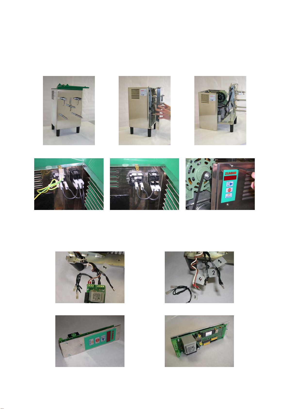
¾Switch off the machine using the switch at the rear.
¾Switch on again while pressing STOP. Four numbers will be displayed
on the screen.
¾With four numbers on the screen (they only appear for 3 seconds)
press the ON button. A number from 0 to 9 will be displayed on the left-
hand side of the screen. The number displayed corresponds to the
tenths of a second delay in stopping the machine, thus if the machine
needs to be stopped sooner, a number lower than that displayed on the
screen needs to be selected. To change this number, press ON (when
the screen is displaying the number on the left-hand side) and the
number will change. For the electronics to store this number in memory,
wait 5 seconds (the screen will then display a number in the central
position, corresponding to the number of oranges selected).
¾Check that the stopping point is correct. If this is not the case, repeat
the process with another delay value.
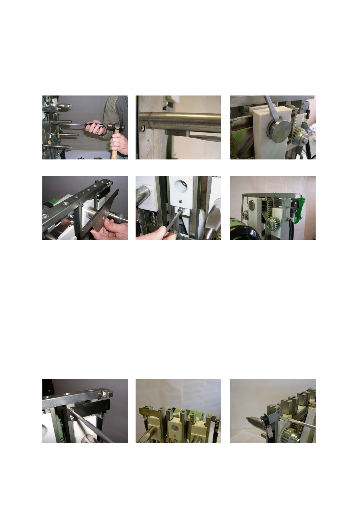
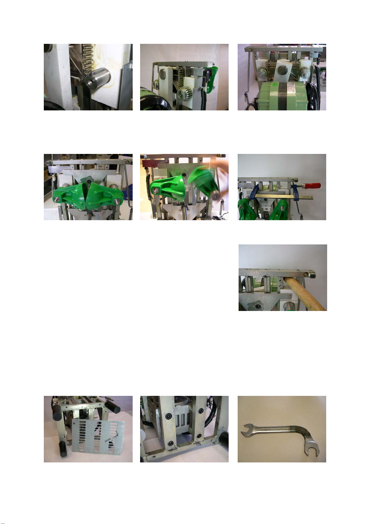
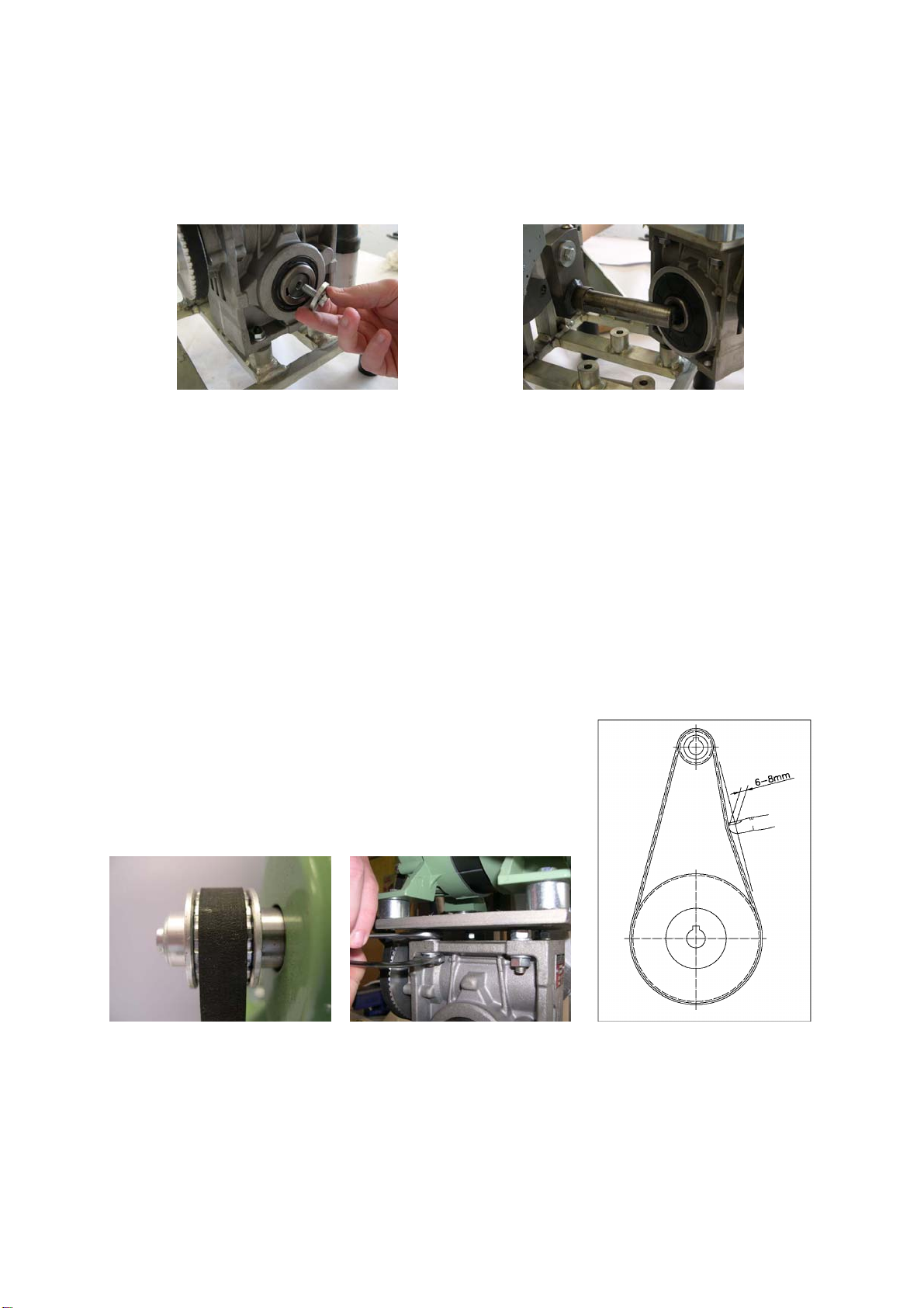
oIf the machine has a registration number earlier than 4376 or if it cannot be
corrected electronically, the position of the micro meter can be altered (Figs.
10a and 10b), and it can be advanced or retarded as necessary.
10a 10b
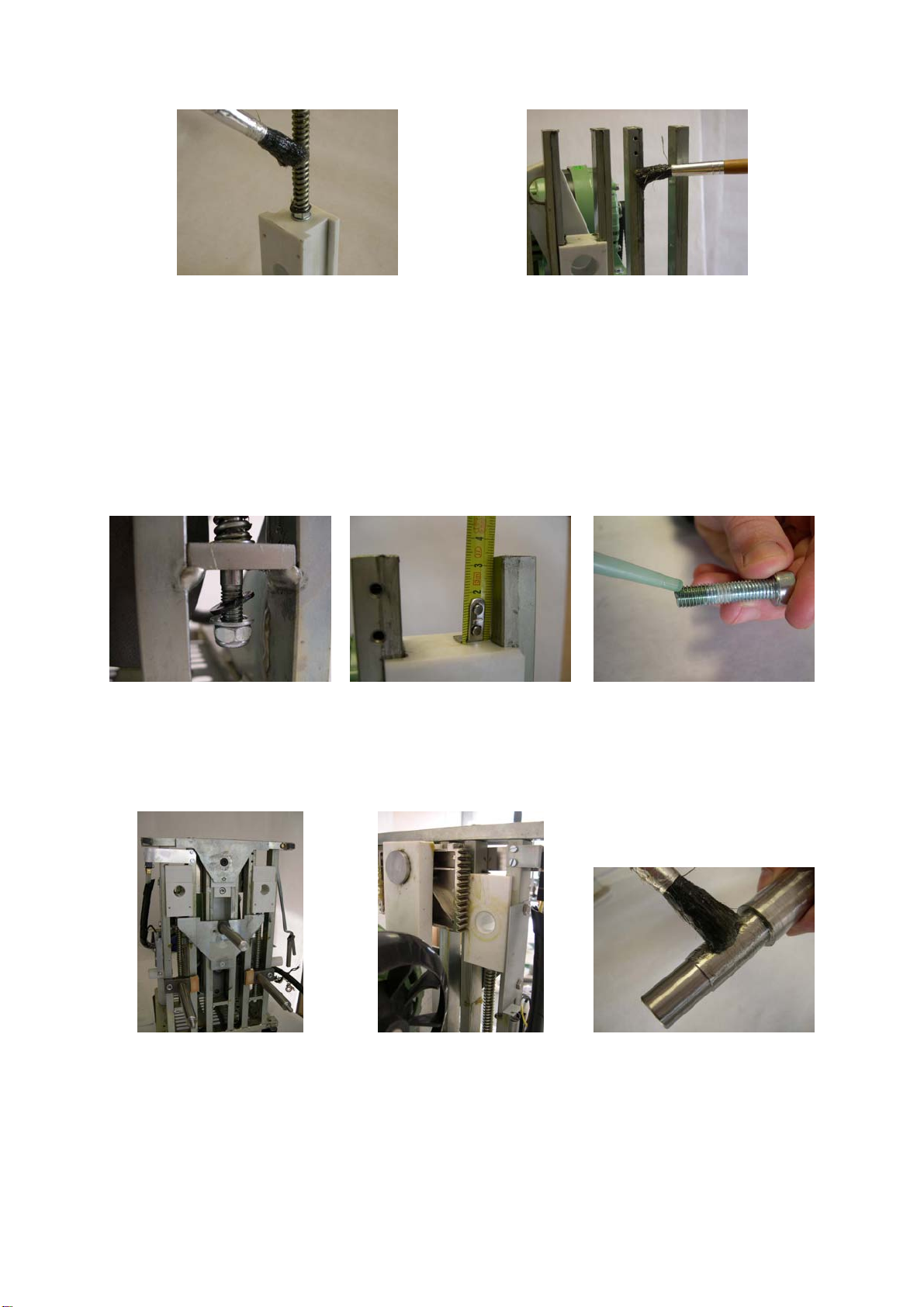
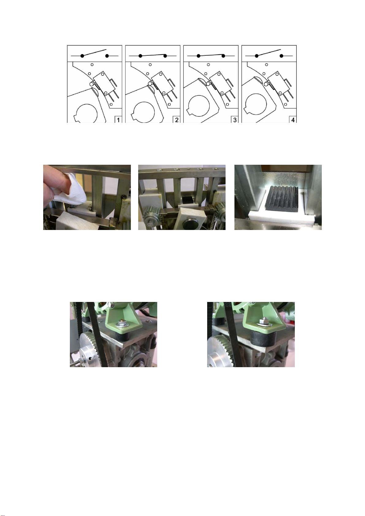
When the micro meter is refitted, it should be adjusted so that there is contact
for almost the whole time the cam is passing, approximately as shown in
Steps 2 and 3 in the following illustration.

011302/01 10
oIt can also be solved by positioning a rubber stop at the top of the bridge
runner. To do so, clean the top surface with solvent, and use adhesive to stick
on the “RUBBER STOP” Ref. 0504024 (Figs. 10c – 10 d – 10e).
10c 10d 10e
11.- BELT CHANGING (MACHINES WITH SHOCK ABSORBERS ON
THE MOTOR MOUNT).
•If the belt fails on a machine with 20Ø shock absorbers (Fig. 11ª), it is advisable
to replace these with the new 30Ø model (Fig. 11b). Ref. T-30/15-M6
“MOTOR MOUNT SHOCK ABSORBER”.
11a 11b
•The belt tension should then be checked. See Point 9 (Figs. 9a – 9b – 9c).

011302/01 11
2.- CLOSING THE MACHINE.
•Grease the inside of the front on the areas rubbing against the runner covers, as
in Fig. 12e.
•Fit the front, checking that the cup shafts are centered with its holes.
•Fit the short micrometer and check that each microswitch is activated before the
micrometer catch finishes latching, as shown Figures 12b and 12 c. Should it
prove necessary, the front can be moved or the micrometer mounts brought
closer.
12a (not activated) 12b (activated) 12c (activated)
•Hook on the spring and position the feed paddle rod facing inwards, (Fig. 12d)
and then fit the rear.
12d 12e
3.- UNLOCKING THE SELECTOR.
Machines between No. 6758 (26-3-2001) and No. 2054050 (April 2005) offered the
possibility of locking the selector. However, this function tended to come on
accidentally, leading to the selector being locked. To unlock it, proceed as follows:
•Switch off the machine using the power supply switch.
•Switch it on again while pressing the SELECT button until the message "on" is
displayed on the screen, indicating that the selector is once more functioning
normally.

011302/01 12
14.- WIRING DIAGRAMS.
1 Fuse
2 Power supply switch
3 Electronic circuit board
4 Meter microswitch
5 Micrometer microswitch
6 Micrometer microswitch
7 Motor
8 Condenser
9 Tray microswitch
10 On/off switch
Table of contents
Other Zummo Juicer manuals

Zummo
Zummo Z1 Nature Technical specifications

Zummo
Zummo Viva Z25-BL, Viva Z25-BR, Viva Z25-GR User manual

Zummo
Zummo Z14 Nature User manual

Zummo
Zummo Z10 User manual

Zummo
Zummo Z06 Nature User manual

Zummo
Zummo Z1 Nature User manual

Zummo
Zummo Z06 Nature User manual

Zummo
Zummo Z40 Technical specifications

Zummo
Zummo Z40 Owner's manual

Zummo
Zummo Z10 User manual

Zummo
Zummo ZO8A User manual

Zummo
Zummo Z1 Nature User manual

Zummo
Zummo Z1 Nature User manual

Zummo
Zummo Z1 Nature User manual

Zummo
Zummo Z40 User manual

Zummo
Zummo Z1 Nature User manual

Zummo
Zummo Z40 Technical specifications

Zummo
Zummo Z40 User manual

Zummo
Zummo Z06-N User manual

Zummo
Zummo Z40 User manual