Zummo Z1 Nature User manual

011216/04
Z 1
KULLANMA KILAVUZU

Español Pag. 03 / 12
English Pag. 13 / 22
Français Pag. 23 / 32
Deutsch Pag. 33 / 42
Italiano Pag. 43 / 52
Português Pag. 53 / 62
Nederlands Pag. 63 / 72
Русский Pag. 73 / 82
Türkçe Pag. 83 / 92

3
ZUMMO-INNOVACIONES MECÁNICAS, S.A. en su constante afán por mejorar sus productos, se reserva
el derecho de modificar las máquinas sin previo aviso; por este motivo el presente libro de instrucciones
puede omitir los últimos cambios efectuados.
INDICE
...........................................................................................................................................Pág.
1 DATOS TÉCNICOS..............................................................................................................03
2 INSTRUCCIONES IMPORTANTES DE SEGURIDAD .......................................................03
3 INSTALACIÓN .....................................................................................................................04
4 PUESTA EN MARCHA ...................................................................................................04-05
5 PARO ...................................................................................................................................05
6 FUNCIÓN CONTADOR .......................................................................................................05
7 FUNCIÓN MARCHA AUTOMÁTICA (sólo modelo Z1Contact)........................................05
8 STAND BY............................................................................................................................06
9 SISTEMAS DE SEGURIDAD..........................................................................................06-07
10 LIMPIEZA.........................................................................................................................07-08
11 ACCESORIOS .....................................................................................................................08
12 MANTENIMIENTO................................................................................................................08
13 CONSEJOS DE UTILIZACION ...........................................................................................08
14 LOCALIZACIÓN DE AVERIAS ......................................................................................08-09
15 ESQUEMA ELÉCTRICO .....................................................................................................09
16 LISTADO DE COMPONENTES .....................................................................................10-11
17 GARANTIA ..........................................................................................................................11
18 RESIDUOS Y RECICLABILIDAD...................................................................................11-12
19 FOTOS ............................................................................................................................93-94
20 PLANOS DE DESPIECES ..............................................................................................95-98
1DATOS TÉCNICOS
CONSUMO (W) 165W
CONSUMO STAND BY (W) 1.8W
NARANJAS POR MINUTO 6.5
CAPACIDAD ALIMENTADOR 1Kg
DIMENSIONES ALTO (mm) 678
ANCHO (mm) 339
FONDO (mm) 387
TAMAÑO DE LA
FRUTA
Ø (mm)
COPA MEDIANA CON SUPLEMENTO (GOMA) 55-70
COPA MEDIANA SIN SUPLEMENTO (GOMA) 63-75
COPA GRANDE CON SUPLEMENTO (GOMA) * 65-80
COPA GRANDE SIN SUPLEMENTO (GOMA) * 75-90
PESO (Kg.) (sin embalaje) 29.5
* accesorio no incluido de serie.
2INSTRUCCIONES IMPORTANTES DE SEGURIDAD
Estimado cliente: Antes de usar su máquina exprimidora, por favor, lea atentamente el manual de
instrucciones.
La máquina ejerce una gran presión al exprimir; por esta razón, no introduzca nunca ni las manos ni
objetos extraños en la zona de exprimido. (Fig. 1)
No se deje nunca flojas las tuercas de sujeción de la copa, de la cuchilla ni de las bandejas, de lo
contrario podría ocasionar serios daños en la máquina. (Fig. 2)
Tenga especial cuidado con la cuchilla, podría cortarse al manipularla. (Fig. 3)
Para evitar riesgos, toda reparación debe hacerse por personal técnico.
No se acepta responsabilidad alguna si la razón del daño es el mal uso del aparato o el no haber
seguido las instrucciones de este manual.
Solicite el servicio de asistencia técnica a la empresa que le suministró la máquina; en caso de no
localizarla, contacte con el fabricante (datos en la portada de este manual).

4
3INSTALACIÓN
¡Atención! la máquina pesa 29.5 Kg. Para trasladar la máquina, le aconsejamos que la cojan entre dos
personas. La mejor forma de cogerla es sujetar con una mano, por debajo del trasero y la otra mano
debajo de la bandeja exprimidora. (Fig. 4)
Coloque la máquina sobre una base suficientemente fuerte y estable.
Asegúrese de que la tensión y frecuencia de la máquina coincide con su instalación eléctrica. Vea la
placa de matrícula. (Fig. 5)
Utilice una base de enchufe provista de una eficaz toma de tierra protegida por un diferencial de 0,03A
conecte a esta base sólo la máquina exprimidora. No la comparta con otros aparatos.
Se recomienda que antes de poner en funcionamiento la máquina, se efectúe una limpieza de las
piezas que van a estar en contacto con el zumo (copa, bandeja exprimido, bola, cuchilla, bandeja filtro,
filtro y carátula).
Conecte el interruptor de red. (Fig. 6 ( I=On, O=Off )). Si no aparece ningún mensaje en pantalla, (Fig.
7) el motivo será falta de tensión; en este caso, deberá asegurarse de haber conectado el enchufe a
una línea con tensión y que el interruptor de red esté accionado. Una vez subsanado este problema,
aparecerá uno de estos mensajes:
(Disp. 1) (Disp. 2)
(Disp. 3) (Disp. 4)
(Disp. 5) (Disp. 6)
a. Si aparece en pantalla el mensaje “3” o cualquier número (Disp. 1), la máquina está dispuesta con
todo correcto y seleccionadas las naranjas a exprimir. En este caso ya puede poner en
funcionamiento la máquina.
b. Si aparece en pantalla el mensaje Error (Disp. 2), la máquina tiene la carátula mal colocada, deberá
colocarla correctamente.
c. Si aparece en pantalla el mensaje Error (Disp. 3), la máquina tiene la bandeja mal colocada, deberá
colocarla hasta el fondo.
d. Si aparece en pantalla el mensaje Error (Disp. 4), la máquina tiene la protección superior mal
colocada, deberá colocarla correctamente.
e. Si aparece en pantalla el mensaje Error (Disp. 5), la máquina tiene la cubeta mal colocada, deberá
colocarla correctamente.
f. Si aparece en pantalla el mensaje Error MEM (Disp. 6), la máquina tiene un error en la placa
electrónica, en este caso deberá llamar al servicio técnico.
4PUESTA EN MARCHA
Según el tamaño de naranjas que vaya a exprimir debe elegir el tamaño de copa y bola y comprobar si
es necesario añadir el suplemento de goma. Vea el capitulo ACCESORIOS MÁQUINA.
Según el tamaño de bola que haya elegido, debe colocar las gomas en el patín. (Figs. 8 - 9)
Coloque todas las piezas en su posición correcta. Ver montaje en punto 10 (limpieza).
Una vez conectada la máquina, el display muestra un número del 1al 50 o la letra C. El número indica
la cantidad de naranjas que se van a exprimir y la letra Csignifica que se exprimirá ininterrumpidamente
durante 30 minutos aproximadamente.

5
Según la cantidad de naranjas que usted desee exprimir, pulse intermitentemente el botón SELECT, el
número que aparece en el visor irá aumentando del 1 al 50 y luego aparecerá la letra C.
(1,2,3,..........48,49,50,C,1,2,3.....) Si por el contrario mantiene presionado SELECT durante más de 2
segundos, el número irá disminuyendo.
Realice esta operación hasta que aparezca la cantidad deseada.
Una vez seleccionada una cantidad y realice un exprimido, esta quedará memorizada aunque apague la
máquina y no cambiará hasta que vuelva a hacer una nueva selección.
Al pulsar el botón ON del panel, la máquina exprimirá el número de naranjas que muestra el display,
indicando durante el proceso el nº de naranjas que le falta por exprimir. Si desea repetir la operación,
basta con pulsar ON. Para detener el proceso pulsar el botón STOP.
5PARO
Estando en marcha, pulse el botón de Stop. El display muestra un Reloj y Stop y la máquina se detiene
cuando se terminan las dos mitades de la naranja y la copa llega a la vertical. Después el display muestra el
número de la anterior selección.
6FUNCIÓN CONTADOR
Si desea conocer el número total de ciclos*realizados, deberá, con la máquina parada y dispuesta,
apretar el botón STOP y en el display se visualizará dicha cantidad durante unos segundos. Tenga en
cuenta que de fábrica todas las máquinas salen con 200 – 250 ciclos debidos a las pruebas para el control
de calidad.
*(ciclo= maniobra completa de exprimido de una fruta)
7FUNCIÓN MARCHA AUTOMÁTICA (sólo modelo Z1Contact)
Apagar la máquina desde el interruptor de red.
Con la máquina apagada, pulsar STOP, mantener pulsado y accionar el interruptor de red, mantener
pulsado durante cuatro segundos y aparecerá una pantalla con cuatro números.
Una vez conseguida esta pantalla buscar el número 4104, pulsando ON controlaremos los dos dígitos de
la izquierda y pulsando SELECT los dos de la derecha, luego pulsar STOP (al pulsar STOP el display
pasará a mostrar ----) y después apagar la máquina con el interruptor de red (si no se apaga la máquina,
no se sale de esta pantalla).
Al volver a conectar la máquina,(se visualiza 1º la versión del programa y después el código 4104) la
máquina comienza a trabajar cuando la fotocélula vea naranjas y debe continuar trabajando hasta que se
acaben las naranjas o se pulse STOP.
Si se para al terminarse las naranjas, bastará con volver a colocar naranjas en la rampa para volver
a poner la máquina en funcionamiento.
Si se pulsa STOP, se parará la máquina y se quedarán las naranjas en la rampa. Para volver a
poner la máquina en marcha:
- Retirar las naranjas de la rampa y volverlas a colocar o pulsar ON.
Importante mantener limpia la óptica de la fotocélula para asegurar la visión. (Fig. 10)
PARA VOLVER A ACTIVAR LA FUNCIÓN NORMAL.
Repetir el proceso introduciendo el código 1001.

6
8STAND BY
La máquina dispone de un sistema de consumo en espera que pasados 5 minutos se activa
automáticamente. Cuando la máquina está en stand by, se apaga la luz del display y se desactivan todos
los símbolos menos el de la máquina.
Para salir de esta situación hay que pulsar cualquiera de los tres botones de la placa.
9SISTEMAS DE SEGURIDAD
La máquina dispone de varios sistemas de seguridad:
1Si la carátula no está bien colocada, el display muestra Error, y está la carátula de forma
intermitente.
2Si la bandeja filtro no está encajada en su sitio, la máquina no funciona y en el display se
muestra Error. La bandeja esta sombreada y de forma intermitente.
3Si la protección superior no está encajada en su sitio, la máquina no funciona y en el display se
muestra Error. La protección esta sombreada y de forma intermitente.
4Si la cubeta no está encajada en su sitio, la máquina no funciona y en el display se muestra
Error. La cubeta esta sombreada y de forma intermitente.
5Si por algún motivo la máquina, estando en marcha, quedara bloqueada, automáticamente
pasados unos segundos se pararía el motor y en el display se mostraría Error e Icono
intermitentes, quedando a la espera de que se elimine la causa del bloqueo.
6La máquina dispone de un sistema de protección térmica en el motor; gracias a éste, en caso
de un recalentamiento, se detiene la máquina y en el display se muestra Error eIcono
Termómetro. En tal caso, deberá esperar aproximadamente diez minutos para que baje la
temperatura; entonces el display cambiará a posición normal. Verifique que las rejillas de
aireación están libres.

7
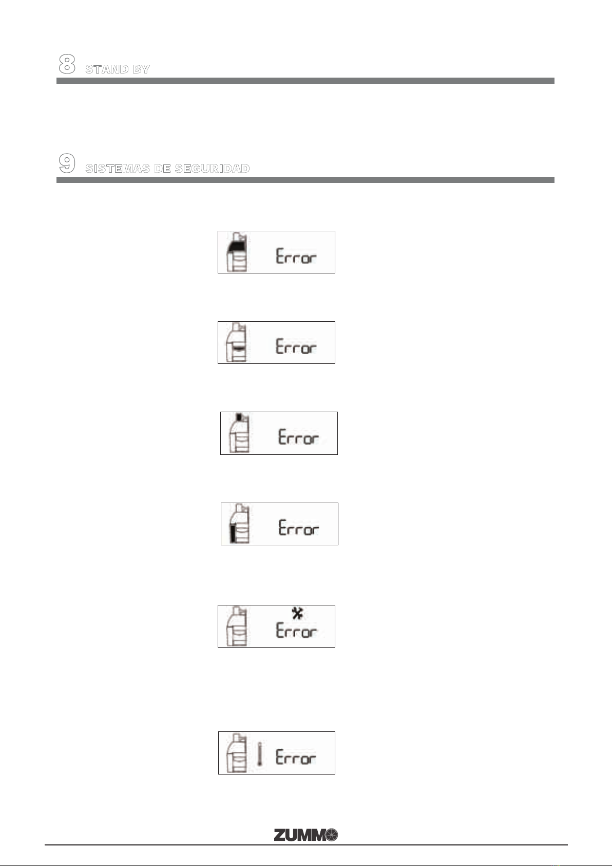
7Si la máquina no muestra ningún mensaje en el display, será debido a falta de tensión.
Compruebe que el interruptor de red esté accionado y que el fusible de seguridad de la base de
red no esté fundido (Fig.11).
10 LIMPIEZA
Recomendamos una limpieza diaria de la zona de exprimido.
Se recomienda parar la máquina presionando Stop antes de cualquier operación de limpieza de la
máquina (nunca parar del interruptor principal), ya que de esta forma todas las piezas a limpiar se
encontrarán situadas en una posición de fácil extracción y colocación. En caso de no seguir esta
recomendación la máquina podría parar en una posición en la que le resultara difícil dicha operación lo
que podría acarrear rotura de piezas por mala colocación de las mismas.
Con la máquina parada siguiendo el proceso anterior DESCONECTE LA MÁQUINA DEL
INTERRUPTOR DE RED. (Fig. 6). El display del selector digital se apagará.
Extraiga el retenedor. ¡Tenga cuidado de no cortarse con el retenedor!
Extraiga la protección superior y la carátula y límpiela con un paño húmedo bañado en una solución
jabonosa neutra (¡ATENCIÓN!: no limpiarla NUNCA con productos que puedan rayarla).
Extraiga primero la cuchilla
Para sacar la copa y la cuchilla le aconsejamos que desenrosque ligeramente las tuercas de sujeción y
apoyándose en ellas, tire hacia afuera; quedarán sueltas y podrá sacarlas con facilidad. ¡Importante,
extraiga primero la cuchilla! Tenga mucho cuidado ya que está muy afilada y podría cortarse.
(fig. 3)
La bandeja filtro, la de exprimido y el patín se extraen desenroscando la tuerca del eje de la bandeja y
tirando hacia afuera horizontalmente. Si desea una limpieza exhaustiva, desenrosque también la bola
que está dentro de la bandeja exprimido (Fig. 12); debajo de la bola debe haber una arandela ¡tenga
cuidado de no perderla!. Puede introducir estas piezas en el lavavajillas o limpiarlas manualmente.
Lave la cubeta, la bandeja y la rejilla posavasos.
Limpie el frente de la máquina con la misma solución jabonosa.
Limpie la rampa y la teja del techo.
Montaje
Después de lavarlo todo, móntelo en el siguiente orden:
1Enrosque la bola en la bandeja exprimido. Previamente observe que está la arandela y ¡APRETAR!
bien la bola. (Fig. 12)
2Revise que el patín tenga las gomas correctamente colocadas (Fig. 8 - 9). Introduzca el patín en el
interior de la bandeja. Monte dicho conjunto por los dos ejes de la máquina simultáneamente
(Fig. 21). Atención para encarar el patín con su eje, levante ligeramente de la pared del patín.
¡Nunca ensamble el patín sobre la bandeja posteriormente!
3Coloque la bandeja filtro y APRIETE bien la tuerca.
4Coloque la copa en el eje y APRIETE bien la tuerca.
5Coloque la cuchilla en el eje y APRIETE bien la tuerca de sujeción. ¡Tenga cuidado de no
cortarse!
6Monte la carátula introduciendo los dos enganches superiores por las ranuras, inserte primero el
enganche derecho y luego el izquierdo. Cuando los coloque notará un pequeño click como que han
encajado y la maquina esta lista.
7Coloque el retenedor en la carátula. (Fig. 20)
8Coloque la protección superior, la bandeja posavasos y la cubeta.
Antes de volver a poner en funcionamiento la máquina, observe:
Que las bandejas y el patín han quedado bien encajados y atornillados.
Que las tuercas de la copa y de la cuchilla están bien apretadas. (Fig. 2)
Que el retenedor está en su posición correcta.
Que el juego de bola y copa (mismo color) son los correctos.
En el caso de que el patín, las bandejas, la bola, la copa, el retenedor o la cuchilla no quedaran bien
colocadas podrían ocurrir daños en dichas piezas e incluso en el interior de la máquina.
(Problemas no cubiertos por la garantía por ser fallos del operador)

8
Cuando la máquina esta lista para funcionar el display mostrará el número de naranjas que va a exprimir.
Nota:
Con el uso de la máquina puede que se produzca una pigmentación de color naranja en las partes de
plástico que están en contacto con el zumo, esto es completamente normal y no supone problema higiénico
ni afecta a las propiedades físicas del plástico.
11 ACCESORIOS
Según el tamaño de la fruta que se quiera exprimir, la máquina dispone de varios juegos de copas y bolas a
elegir:
Copa y bola de color gris oscuro, con el que puede exprimir frutas de diámetro 63 a 75. Si desea
exprimir frutas de diámetro 55 a 70 deberá colocar el suplemento elástico. (Fig. 13)
Opcional. Copa y bola de color gris claro con el que puede exprimir frutas de diámetro 75 a 90. Si
desea exprimir frutas de diámetro 65 a 80 deberá colocar el suplemento elástico. (Fig. 14)
Independientemente del juego que se monte, la cuchilla siempre será la misma.
¡ATENCIÓN!: no deben mezclarse elementos de distintos juegos.
12 MANTENIMIENTO
El mantenimiento exterior de la máquina se limita a su limpieza.
En el interior de la máquina cada 300.000 ciclos se deben engrasar las guías, sustituir los muelles y realizar
una limpieza exhaustiva.
Engrasar periódicamente el eje de la teja alimentadora. (Fig. 15). Utilice siempre grasa apta para uso
alimentario.
13 CONSEJOS DE UTILIZACIÓN
Compruebe que las naranjas entren bien en la copa que elija para exprimir, pues si la copa es
demasiado pequeña, pellizcará la corteza y sacará aceite, en este caso el zumo tendrá sabor amargo.
Para obtener la mayor cantidad de zumo posible, es conveniente que la copa no sea mucho más
grandes que las naranjas que esté utilizando.
Cuando finalice la jornada apague la máquina utilizando el interruptor de red. (Fig. 6)
14 LOCALIZACIÓN DE AVERIAS
Avería Causa y/o solución
El display no se ilumina Falta tensión eléctrica en la red.
Fusible fundido. (Fig. 11)
Cable de red mal conectado.
Accione el interruptor de red. (Fig. 6)
Humedad en placa electrónica. Proporcionar calor seco a la placa.
Aparece Error en el
display Carátula mal colocada. (Fig. 16)
Bandeja filtro fuera de su sitio. (Fig.17)
Protección superior mal colocada. (Fig. 18)
Cubeta mal colocada. (Fig. 19)
Sobrecalentamiento motor.
Ver sección 9.
Aparece Error e Icono
intermitente en el
display.
Vea si está exprimiendo naranjas congeladas.
Observe si se han amontonado cortezas en la bandeja exprimidora.
Vea si se ha dejado la bola desenroscada.
Vea si las cortezas se quedan pegadas en el interior de la copa.
Compruebe que no ha montado copa y bola de diferentes tamaños.
La corteza de la fruta es demasiado gruesa. Retire la arandela de debajo
de la bola.

9
Máquina bloqueada Para desbloquear la máquina utilizar una llave allen de 3mm que
encontrará a la derecha de la rejilla inferior de la máquina. Introducirla en
el agujero del lateral derecho, y con la máquina desconectada, girar en
sentido horario hasta subir la copa y deshacer el bloqueo. ATENCIÓN:
antes de conectar la máquina, asegúrese de que ha sacado la llave de su
anclaje.
Rotura del patín Se han soltado las gomas y se amontonan las cortezas en la bandeja de
exprimido.
Tuerca de la copa mal apretada.
La bola de la bandeja exprimidora estaba suelta.
Las naranjas no quedan
suficientemente
exprimidas
La corteza de la fruta es demasiado fina. Compruebe que está la arandela
debajo de la bola, coloque como máximo una arandela.
La segunda mitad de la
naranja se da la vuelta Utilización de naranja muy pequeña para el juego de copa y bola utilizado.
Montar el juego mediano o la copa con el suplemento elástico.
Comprobar las medidas de las naranjas en el calibrador.
La naranja rebota en la
copa y salta a la cuchilla Utilización de naranja muy grande para el juego de copa y bola utilizado.
Montar el juego grande con el suplemento elástico.
Comprobar las medidas de las naranjas en el calibrador.
La naranja salta de la
teja alimentadora El eje de la teja alimentadora está reseco; proceda a engrasarlo. (Fig. 15)
Para cualquier consulta o petición de repuestos, deberá indicar modelo y número de matrícula de su
máquina (Fig. 5).
15 ESQUEMA ELÉCTRICO
1 Fusible
2 Interruptor de red
3 Placa electrónica
4 Sensor protección superior
5 Microinterruptor carátula
6 Microinterruptor bandeja
7 Motor
8 Sensor cubeta
9 Microinterruptor contador
10 Condensador
11 Fotocélula

10
16 LISTADO DE COMPONENTES
0502007A ENGANCHE CARÁTULA 2003
0503001 TEJA ALIMENTADORA
0504013 PASADOR CHAPA EMPUJADORA
0504014-1 CORREDERA COPAS CON INSERTO
0504020 JUNTA NITRILO
0505016 GOMA EXTRACCIÓN CORTEZA
0506005/1 FLEJE MICRO CARÁTULA
0506006/1 FLEJE MICRO BANDEJA
0506007 MICRO CORTO
0506008 MICRO LARGO
0506010 CABLE DE RED
0506014 BASE DE RED CON FUSIBLES
0506015 INTERRUPTOR BIPOLAR NEGRO
0506021 PASAMURO CHAPA ZUMMITO
0506027 TAPON PLÁSTICO Ø17,3
0508013 SOPORTE DE GOMA 85mm
1003031 TUERCA CARÁTULA
1901001 CHASIS
1901002 CIERRE CHASIS
1901003 EJE BANDEJA
1902001 FRENTE
1902002 CUERPO
1902003 TAPA INFERIOR
1902004 TECHO
1902005 CARÁTULA COMPLETA
1902006 ENGANCHE CARÁTULA IZQUIERDO
1902007 RETENEDOR
1902008 CARÁTULA
1902009 TOPE CUBETA
1902010 PROTECCIÓN SUPERIOR
1902011 TOPE BANDEJA
1902012 ADHESIVO ALIMENTACIÓN
1902013 ADHESIVO CALIBRES
1902015 TECHO Z1 CONTACT
1903001 BANDEJA EXPRIMIDO
1903002 BANDEJA FILTRO
1903003 FILTRO
1903004 BOLA MEDIANA
1903005 BANDEJA POSAVASOS
1903006 REJILLA POSAVASOS
1903008 CUBETA
1903010 BOLA GRANDE
1904001 SOPORTE PATÍN
1904002 CORREDERA PATÍN
1904003 CUBRE CORREDERA PATÍN
1904004 PATÍN COMPLETO
1905001 REDUCTOR U40
1905002 EJE REDUCTOR
1905003 POLEA 48
1905004 CONJUNTO COPIADOR
1905007 BIELA
1905008 ARANDELA 30
1905009 SUPLEMENTO REDUCTOR
1906001 MOTOR 230V-50Hz
1906001A MOTOR 240V-250V 50Hz
1906001B MOTOR 110V 60Hz
1906001C MOTOR 220V 60Hz
1906002 CORREA 160XL 037
1906003 POLEA 17XL
1906004 CONDENSADOR 230V
1906004A CONDENSADOR 110V
1906004B CONDENSADOR 240V
1907001 PUENTE
1907002 CONJUNTO EMPUJADOR
1907003 BULÓN PUENTE
1907004 IMÁN PUENTE
1907006 CUÑA TRINQUETE
1907007 EJE CUÑA
1907008 CORREDERA PUENTE
1907009 TOPE PUENTE
1908001 TIRANTE CORREDERA COPA
1908002 CUBRE CORREDERA COPA
1908003 EJE COPA
1908004 PIÑON
1908005 RESORTE CORREDERA COPA
1908006 COPA GRANDE
1908007 COPA MEDIANA
1908012 CALIBRADOR COPA MEDIANA
1908013 CALIBRADOR COPA GRANDE
1908014 SUPLEMENTO ELÁSTICO COPA MEDIANA
(148mm)
1908015 SUPLEMENTO ELÁSTICO COPA GRANDE
(174mm)
1908016 KIT COPA-BOLA GRANDE Z1
1909001 COJINETE EJE CUCHILLA
1909002 EJE CUCHILLA
1909003 PALPADOR CUCHILLA
1909006 CUCHILLA
1909007 MUELLE CUCHILLA
1910001 EJE TRINQUETE
1910002 TRINQUETE
1910003 MUELLE LEVA TRINQUETE
1910005 MUELLE TRINQUETE
1910006 CORREDERA TRINQUETE
1910007 SUPLEMENTO CORREDERA TRINQUETE
1910009 GUIA TRINQUETE
1911001 CUADRADILLO TEJA
1911002 ACCIONADOR TEJA
1912001 SOPORTE SENSOR MAGNÉTICO
1912002 SOPORTE MICRO IZQUIERDA
1912005 PLACA CPU 230V
1912005A PLACA CPU 110V
1912006 SEPARADOR PLACA
1912007 SERIGRAFIA PLACA CPU
1912012 SENSOR TECHO
1912013 SENSOR CUBETA
1912014 FOTOCÉLULA Z1 CONTACT
2/1/1 EMBELLECEDOR EJE CON PLETINA
3/9/1G TAPÓN LATERAL GRIS
4/9 POLEA MOTOR 14XL 037
6/2 BULÓN PORTARODAMIENTO
ROD.608ZZ RODAMIENTO
I-125-M4 INOX. ARANDELA PLANA M4 DIN-125
I-125-M10 INOX. ARANDELA PLANA M10 DIN-125
T-125-M8 ARANDELA PLANA M8 DIN-125 CINCADA
T-912-M8X45 TORNILLO ALLEN M8X45 DIN-912 CINCADO
T-934-M8 TUERCA EXAG. M8 DIN-934 CINCADA
I-965-M4X10 INOX. TOR. AVELLAN. M4X10 DIN-965
T-985-M8 TUERCA FRENO M8 DIN-985 CINCADA
I-1587-M4 INOX. TUERCA CIEGA M4 DIN-1587

11
I-7982-Ø3.5X9.5 INOX. TOR. R.CHAPA Ø3.5X9.5 DIN-7982
I-PERNO-FHS
M4X10 PERNO INSERT. INOX FHS M4X10
V0133 ARANDELA SUPLEMENTO BOLA
V0162 ADHESIVO USO CARÁTULA Z05/Z14
V0184 SOPORTE LLAVE ALLEN 3MM
V0185 LLAVE ALLEN 3MM
V0192 KIT ENGANCHE CARÁTULA Z1
17 GARANTIA
ZUMMO-INNOVACIONES MECÁNICAS, S.A. a través de su distribuidor oficial, garantiza sus máquinas por
un período de 3 AÑOS o 100.000 ciclos de exprimido, que entrará en vigor a partir de la fecha de
ENTREGA al distribuidor, de acuerdo a las siguientes condiciones:
Esta garantía cubre todo defecto de los materiales o fabricación.
Si la máquina muestra algún defecto durante su uso normal dentro del período de garantía, las piezas
defectuosas serán reemplazadas sin cargo.
La garantía tendrá validez solamente cuando se presente la factura original de compra.
La reparación o sustitución de piezas durante el periodo de garantía, no implica una extensión de la fecha
de finalización de esta.
Los repuestos originales ofrecen una garantía de 6 meses.
Esta garantía no cubre
Cualquier daño no causado directamente por defecto de fabricación o en los materiales.
Cualquier daño debido a una incorrecta instalación, abuso, uso indebido, alteración, accidente o
negligencia.
El rayado de cualquiera de las piezas de plástico por utilizar elementos que puedan ocasionar rayado como
los estropajos en la limpieza.
Mano de obra de reparaciones no incluida en esta garantía.
Cualquier daño causado por personal o materiales no autorizados.
Los defectos causados por desgaste de uso; en particular el siguiente componente:
0505016 GOMA EXTRACCIÓN CORTEZA.
1908014 SUPLEMENTO ELÁSTICO COPA MEDIANA (148mm)
1908015 SUPLEMENTO ELÁSTICO COPA GRANDE (174mm)
Asistencia técnica
Para cualquier consulta técnica, preferentemente debe ponerse en contacto con su distribuidor habitual, o
puede dirigirse a Zummo a través de:
E-mail: [email protected]
Teléfono: 961.301.246
Fax: 961.301.250
Cualquier reparación durante el período de garantía, no autorizada por ZUMMO, causará automáticamente
la anulación de esta.
18 RESIDUOS Y RECICLABILIDAD
Equipos fuera de uso
Unión Europea Este símbolo indica que los aparatos eléctricos y electrónicos que lo llevan no deben
desecharse junto con la basura doméstica general. Si desea desechar este equipo, ¡no
utilice el cubo de basura ordinario! Existe un sistema de recogida especial para estos
productos.

12
Para obtener más información sobre el punto de recogida y el reciclaje de este producto, póngase en
contacto con su servicio de recogida municipal, su gestor de residuos o el distribuidor que le haya vendido
el producto.
Si desecha el producto adecuadamente, estará ayudando a preservar los recursos naturales (recuperación
de materiales) y a prevenir los posibles efectos negativos en el medio ambiente y en la salud de las
personas que podría provocar el tratamiento incorrecto del producto desechado.
La eliminación inadecuada de estos desechos puede suponer sanciones, de acuerdo con la legislación
nacional.
Otros países no pertenecientes a la Unión Europea
Si desea desechar este producto, hágalo de conformidad con la legislación nacional vigente u otras
normativas de su país para la gestión de residuos de equipos eléctricos y electrónicos usados.
Embalaje
Para su eliminación tenga en cuenta las normas locales de tratamiento de este tipo de residuos. Separe los
distintos materiales de desperdicio del embalaje y entréguelos al centro de recogida selectiva de residuos
más cercano.

13
ZUMMO, INNOVACIONES MECÁNICAS, S.A., in an ongoing effort to improve its products, reserves the
right to modify machines without prior warning; for this reason, the present instruction booklet may not
include the last product updates.
INDEX
.........................................................................................................................................Page:
1 TECHNICAL DATA ..............................................................................................................13
2 IMPORTANT SAFETY INSTRUCTIONS ............................................................................13
3 INSTALLATION ...................................................................................................................14
4 START UP ......................................................................................................................14-15
5 STOPPING ...........................................................................................................................15
6 COUNTER FUNCTION ........................................................................................................15
7 AUTOMATIC START FUNCTION (only Z1Contact model)...............................................15
8 STAND BY............................................................................................................................16
9 SAFETY SYSTEMS..............................................................................................................16
10 CLEANING ...........................................................................................................................17
11 ACCESSORIES ...................................................................................................................18
12 MAINTENANCE....................................................................................................................18
13 ADVICE FOR USE ...............................................................................................................18
14 IDENTIFYING DAMAGES ..............................................................................................18-19
15 ELECTRICAL DIAGRAM ....................................................................................................19
16 LIST OF COMPONENTS ................................................................................................19-20
17 GUARANTEE ......................................................................................................................21
18 WASTE AND RECYCLABILITY .....................................................................................21-22
19 PHOTOS .........................................................................................................................93-94
20 PARTS DIAGRAMS ......................................................................................................95-98
1TECHNICAL DATA
CONSUMPTION (W) 165W
STAND BY CONSUMTION (W) 1.8W
FRUITS PER MINUTE 6.5
HOPPER CAPACITY 1Kg
DIMENSIONS HEIGHT (mm) 678
WIDTH (mm) 339
DEPTH (mm) 387
FRUIT SIZE
Ø (mm)
REGULAR CUP WITH SUPPLEMENT (RUBBER) 55-70
REGULAR CUP WITHOUT SUPPLEMENT (RUBBER) 63-75
LARGE CUP WITH SUPPLEMENT (RUBBER) * 65-80
LARGE CUP WITHOUT SUPPLEMENT (RUBBER) * 75-90
NET WEIGHT (Kg.) 29.5
* optional accessories, not included as standard.
2IMPORTANT SAFETY INSTRUCTIONS
Dear customer: Before starting to use your juicer for the first time, please read this instructions manual
carefully.
The machine exerts a great deal of pressure when operating; for this reason, never place hands or other
objects in the squeezing area. (Fig. 1)
Never allow the screws affixing the cup, the blade or the trays to become loose as this could cause
serious damage to the machine. (Fig. 2)
Take special care when handling the Blade to avoid the risk of injury. (Fig. 3)
To prevent any risks, all repairs should be performed by technical personnel.
ZUMMO assumes no liability whatsoever if damage is due to improper machine use or failure to follow
the instructions contained in this manual.
You should seek technical support from the distribution company that supplied your machine; in the
event that you cannot locate it; contact the factory (details on the cover of this manual).

14
3INSTALLATION
Important! The machine weighs 29.5 kg. The machine should always be moved by two people. The best
way to lift the machine is to use one hand to get a grip underneath the machine rear and the other hand
placed beneath the Squeezing Tray. (Fig. 4)
Place the machine on a sufficiently sturdy and stable base.
Fit all the parts in the correct position. You can see assembly in point 10 (cleaning).
Make sure that the machine’s voltage and frequency match the values of your electrical installation. See
the identification plate. (Fig. 5)
Use an electrical outlet equipped with an effective earth connection (0.03A). This outlet should be used
exclusively by the juice extraction machine. Do not plug other appliances into the outlet.
Before operating the machine, wash all machine parts that will be in contact with juice; Cup, Ball, Blade,
Juicer tray, Filter Tray, Filter and Front Cover.
Turn ON the power switch (Fig. 6 (I=On, O=Off)). If no message appears on the display (Fig. 7), there is
lack of power supply. Make sure you have connected the plug to a powered circuit and that the power
switch is switched on. Once this is done, the Programmer display will show one of the following
messages:
(Disp. 1) (Disp. 2)
(Disp. 3) (Disp. 4)
(Disp. 5) (Disp. 6)
a. If the display shows a number (Disp. 1), the machine is ready to start operating.
b. If the display shows the Error message (Disp. 2), then the Front Cover is not correctly assembled
and should be re-assembled correctly.
c. If the display shows the Error message (Disp. 3), the Juicer tray is not correctly assembled and
should be re-assembled correctly.
d. If the display shows the Error message (Disp. 4), the upper protective device is not properly fitted
and should be re-fitted correctly.
e. If the display shows the Error message (Disp. 5), the bin is not fitted properly and should be re-fitted
correctly.
f. If the display shows the Error MEM (Disp. 6), it means the Programmer is faulty. Contact your local
supplier for technical assistance.
4START UP
Choose the right cup and ball size, depending on the size of the oranges you intend to juice, and check
whether you need to add the rubber accessory. See chapter on MACHINE ACCESSORIES.
Depending on the size of ball you have chosen, you should fit the rubber accessory to the guide plate.
(Figs. 8 - 9)
Fit all parts in the correct position. You can see assembly in point 10 (cleaning).
Once the machine is switched on, the display will show either a number between 1and 50 or the letter
C. The number indicates the quantity of fruits to be squeezed, while the letter Csets the machine to
squeeze continuously for approximately 30 minutes.
To set the number of oranges to squeeze, press the SELECT button repeatedly to increase the number
(from 1 to 50, followed by the letter C; 1,2,3,..........48,49,50,C,1,2,3.....). Alternatively, press and hold the
SELECT button for 2 seconds and the number will decrease. Continue until you visualize the wanted
number.

15
The selected number will be stored on the display after the first complete squeeze cycle is finished. The
number will be stored even if the machine is switched off. You may change the number repeating the
complete number selection process.
Press the ON button to start squeezing. During the process, the display will show the remaining amount
of fruits to be squeezed. If you wish to repeat the process, simply press ON. To stop the process, press
the STOP button.
5STOPPING
With the machine running, press the Stop button. The display will show the Timer and the word Stop and
the machine will stop when the two halves of the orange have been squeezed and the cup has reached the
vertical position. The display will then show the number of the previous selection.
6COUNTER FUNCTION
The display stores the total number of cycles* completed. To visualize the figure,
With the machine stopped and in stand-by, press the STOP button
The figure will appear on the display for a few seconds.
Bear in mind that all machines show a minimum of 200 to 250 cycles completed for quality control testing.
*(cycle = complete set of movements to squeeze a piece of fruit)
7AUTOMATIC START FUNCTION (only Z1Contact model)
Turn off the machine at the mains.
With the machine turned off, press STOP, keep it pressed and turn the machine on at the mains; keep it
pressed for 4 seconds and the display will show four numbers.
When you have reached this point, look for the number 4104; by pressing ON you control the two digits on
the left and by pressing SELECT you control the two digits on the right; then press STOP (when you press
STOP the display will show ----) and then turn off the machine at the mains (if the machine is not switched
off, it cannot leave this screen display).
When you turn on the machine again (first you see the programme version and then the number 4104), it
will start operating when the photocell detects oranges and will continue operating until the oranges are
finished or you press STOP.
If it stops when the oranges have finished, you simply need to put more oranges on the ramp to put
the machine back into operation.
If you press STOP, the machine will stop and the oranges will remain on the ramp. To turn the
machine back on again:
- Remove the oranges on the ramp and then put them back again or press ON.
Important: keep the lens of the photocell clean to ensure it can visualize the fruit properly. (Fig. 10)
TO RETURN TO THE STANDARD OPERATING SYSTEM.
Repeat the process by entering code 1001.

16
8STAND BY
The machine has a stand-by power-saving system which is activated automatically after 5 minutes. When
the machine is on stand-by, the display light goes out and all the icons except the one for the machine are
disabled.
To exit this situation, press any of the three buttons on the plate.
9SAFETY SYSTEMS
The machine has various safety systems:
1If the cover is not fitted properly, the display shows the Error message with the area of the cover
flashing.
2If the Juicetray is not assembled or improperly assembled, the machine will not operate and the
display will show Error message. The tray flashes as a shadow.
3If the upper protective device is not fitted properly the machine will not work and the display
shows the Error message with the area of the protective device flashing.
4If the bin is not fitted properly, the machine will not work and the display will show the Error
message along with the area of the filter tray flashing.
5If for any reason the machine gets blocked during operation, after a few seconds the motor will
stop automatically and the display will show Error message with a faulty flashing icon, until the
cause of the blockage is removed.
6Thanks to a thermal protection system in the motor, in the event of overheating the machine will
stop and the display will show Error message and a thermometer icon. In this case, please wait
around 10 minutes to allow the motor temperature to decrease. The error message will
disappear. Please check that the ventilation gratings are not obstructed.
7If there is no message on the display, it means there is no power supply. Check that the power
switch is on and that the plug fuse is not burnt out (Fig.11).

17
10 MACHINE CLEANING
The machine squeezing area and parts must be cleaned daily.
If the machine is in operation, always stop it using the Programmer STOP bottom. Never attempt to stop
the machine using the mains switch. Failure to follow this recommendation will cause the machine to
stop in a position that impedes cleaning; possibly leading to breakage of parts due to poor handling.
Disconnect the machine using the power switch. (Fig. 6)
Remove the retainer. Take care not to cut yourself on the retainer!
Remove the upper protective piece and the cover and clean them with a cloth dampened in a neutral
soapy solution (IMPORTANT: NEVER use abrasive cleaning products which might scratch the surface).
First remove the blade.
To remove the cup and the blade, we recommend you gently loosen the assembly nuts and gently pull
them outwards; they will then become loose and you can remove them easily. Important: remove the
blade first! Take great care as it is very sharp and you could easily cut yourself. (Fig. 3)
The bin, the juicer tray and the guide plate are removed by unscrewing the nut on the shaft of the tray
and pulling outwards horizontally. If you are doing an exhaustive clean, also unscrew the ball inside the
juicing tray (Fig. 12); underneath the ball there should be a washer – make sure you don’t lose it!
You can put these parts in a dishwasher or clean them by hand.
Wash the container, the tray and the cup grille.
Clean the front of the machine with the same neutral soapy solution.
Clean the ramp and the cover tile.
Assembly
After cleaning the whole unit, it is re-assembled as follows:
1Screw the ball into the juicer tray. Make sure the washer is in place first and then TIGHTEN the ball
well. (Fig. 12)
2Check that the rubber accessories on the guide plate are fitted properly (Figs. 8 - 9). Insert the guide
plate into the tray. Assemble this set using the two shafts of the machine at the same time (Fig.
21). Make sure the guide plate couples with its shaft, gently lifting the wall of the guide plate. Never
fit the guide plate to the tray afterwards!
3Fit the filter tray and TIGHTEN the nut well.
4Fit the cup to the shaft and TIGHTEN the nut well.
5Fit the blade to its shaft and TIGHTEN the nut well. Take care not to cut yourself!
6Assemble the cover by inserting the two upper parts along the grooves, insert the right cover clasp
first and later the left cover clasp. When they are properly fitted you will hear a small ‘click’ and then
the machine is ready.
7Fit the retainer to the cover. (Fig. 20)
8Fit the upper protective device, the cup-holder tray and the bin.
Before operating the machine, make sure that:
The trays and the guide plate are properly coupled and screwed in.
The nuts of the cup and the blade are properly tightened. (Fig. 2)
The retainer is in the right position.
The ball and cup set (in the same colour) are the correct ones.
If the guide plate, trays, ball, cup, retainer or blade are not in the correct position, it could damage the parts
themselves or even the interior of the machine.
(Operator faults not covered by the guarantee)
The display will show the number of oranges to be squeezed. The machine is now ready for operation.
Important Notice
The normal use of the machine may cause the plastic parts that are exposed to juice to turn orange. This is
completely normal and does not imply a hygiene problem or affect the physical properties of the plastic.

18
11 MACHINE ACCESSORIES
The machine has various squeezing sets of Cups and Balls to use depending on the size of the fruit you
wish to squeeze.
Cup and ball in dark grey, for juicing fruit with a diameter of 63 to 75. If you need to squeeze
fruit with a diameter of 55 to 70, you need to fit the elastic accessory. (Fig. 13)
Optional. Cup and ball in light grey, for juicing fruit with a diameter of 75 to 90. If you need to
squeeze fruit with a diameter of 65 to 80, you need to fit the elastic accessory. (Fig. 14)
Regardless of the squeezing set use, the Blade will always be the same.
ATTENTION!: Never mix components of different sets.
12 MACHINE MAINTENANCE
Exterior machine maintenance: simply requires daily cleaning.
Interior of the machine: After every 300,000 cycles, the inner machine guides and springs must be lubricated
and a full cleaning carried out.
Periodically lubricate the paddle shaft. (Fig. 15). Always use a lubricant approved for use with food products.
13 ADVICE FOR USE
Check that the oranges fit well in the cup you have chosen for squeezing, as if the cup is too small it will
score the peel and release the oil, giving the juice a bitter taste.
To get the maximum amount of juice, the cup should only be a little larger than the oranges you are
using.
We recommend turning off the machine when it is not going to be used. (Fig. 6)
14 IDENTIFYING DAMAGES
Damage Cause and/or solution
The display is not lit No power supply.
Fuse burnt out. (Fig. 11)
Power cable not properly connected.
Switch power on. (Fig. 6)
Damp in circuit board. Supply dry heat to the board.
The display shows
message Error Cover badly fitted. (Fig. 16)
Filter tray out of place. (Fig.17)
Upper protective device badly fitted. (Fig. 18)
Bin badly fitted. (Fig. 19)
Motor overheating.
See section 9.
The display shows
message Error and a
flashing Icon.
Check to see if the oranges being squeezed are frozen.
Check to see if peel has built up in the juicer tray.
Check to see if the ball has not been properly screwed in.
Check to see if peel has become stuck inside the cup.
Check that you haven’t fitted different sizes of cup and ball.
The skin of the fruit may be too thick. Remove the washer from underneath
the ball.

19
Blocked machine To unblock the machine, use the 3mm Allen key to the right of the lower
grille of the machine. Insert it into the hole on the right-hand side and, with
the machine unplugged, turn it in a clockwise direction until you can raise
the cup and release the blockage. IMPORTANT: before plugging in the
machine, make sure you have removed the key from its fitting.
Breakage of guide plate The Peel Extracting Bands are loose or broken and peel is piling up in the
Juicer tray.
The nut of the cup is not tight enough.
The ball in the squeezer tray is loose.
Not enough juice is being
extracted from the fruit The skin of the fruit is too thin. Check that the washer is fitted underneath
the ball; fit a maximum of one washer.
The second half of the
orange turns around Orange may be too small for the cup and ball set being used. Fit the
medium set, or the cup with the elastic accessory.
Check the size of the oranges in the calibrator.
The orange rebounds in
the cup and misses the
blade
Orange may be too large for the cup and ball set being used. Fit the large
set with the elastic accessory.
Check the size of the oranges in the calibrator.
Oranges pop out from the
paddle The paddle shaft is too dry; proceed to grease it. (Fig. 15)
For any advice or to request spare parts, you should state the model and serial number of your machine (Fig.
5).
15 ELECTRICAL DIAGRAM
1 Fuse
2 Power switch
3 Circuit board
4 Superior protection sensor
5 Front-cover micro-switch
6 Tray micro-switch
7 Motor
8 Bin sensor
9 Counter micro-switch
10 Condenser
11 Photocell
16 LIST OF COMPONENTS
0502007A COVER CLASP
0503001 FEEDER PADDLE
0504013 PRESS PLATE FASTENER
0504014-1 CUP SLIDE
0504020 PLASTIC WASHER 7,5/15 X 1,5
0505016 PEEL EXTRACTING BANDS
0506005/1 FRONT COVER MICRO HOOP
0506006/1 SQUEEZING TRAY-MICRO CLAMP
0506007 MICRO (SHORT)
0506008 MICRO (LONG)

20
0506010 ELECTRIC LEAD
0506014 POWER BASE
0506015 BLACK BIPOLAR SWITCH
0506021 CONNECTION
0506027 BLANKING PLUG Ø17,3
0508013 MACHINE FOOT 85MM
1003031 SQUEEZER FRONT COVER NUT
1901001 CASING UNIT
1901002 CASING CLOSURE
1901003 SQUEEZING-TRAY SHAFT
1902001 FRONT
1902002 BODY
1902003 LOWER COVER
1902004 SQUEEZER TOP
1902005 COMPACT FRONT COVER
1902006 LEFT-HAND COVER SCREW
1902007 RETAINER
1902008 COMPACT FRONT COVER (PLASTIC ONLY)
1902009 BIN BUFFER
1902010 UPPER PROTECTIVE DEVICE
1902011 TRAY BUFER
1902012 FEED STICKER
1902013 CALIBRE STICKER
1902015 Z1 CONTACT SQUEEZER TOP
1903001 JUICER TRAY
1903002 FILTER TRAY
1903003 FILTER
1903004 MEDIUM BALL
1903005 DRIP TRAY
1903006 DRIP VENT
1903008 BIN
1903010 LARGE BALL
1904001 GUIDE PLATE SUPPORT
1904002 GUIDE PLATE RUNNER
1904003 GUIDE PLATE RUNNER COVER
1904004 FULL GUIDE PLATE
1905001 U40 REDUCER
1905002 U40 REDUCER OUTPUT SHAFT
1905003 48 REDUCER PULLEY
1905004 COPIER UNIT
1905007 ROD
1905008 30 WASHER
1905009 REDUCER SUPLEMENT
1906001 230-50Hz MOTOR
1906001A 240V-250V 50Hz MOTOR
1906001B 110V 60Hz MOTOR
1906001C 220V 60Hz MOTOR
1906002 BELT 160XL 0.37
1906003 17XL PULLEY
1906004 230V CONDENSER
1906004A 110V CONDENSER
1906004B 240V CONDENSER
1907001 BRIDGE
1907002 THRUST UNIT
1907003 BRIDGE PIN
1907004 BRIDGE MAGNET
1907006 WEDGE-SHAPED RATCHET
1907007 RATCHET SHAFT
1907008 BRIDGE GUIDE
1907009 BRIDGE BUFFER
1908001 CUP GUIDE BRACE
1908002 CUP GUIDE COVER
1908003 CUP SHAFT
1908004 PINION
1908005 CUP GUIDE ELASTIC
1908006 LARGE CUP
1908007 MEDIUM CUP
1908012 MEDIUM CUP CALIBRATOR
1908013 LARGE CUP CALIBRATOR
1908014 MEDIUM CUP ELASTIC SUPPLEMENT
(148mm)
1908015 LARGE CUP ELASTIC SUPPLEMENT (174mm)
1908016 LARGE CUP-BALL Z1 KIT
1909001 BLADE SHAFT BEARING
1909002 BLADE SHAFT
1909003 BLADE PROBE
1909006 BLADE
1909007 BLADE SPRING
1910001 RATCHET SHAFT
1910002 RATCHET
1910003 RATCHET LIFT SPRING
1910005 RATCHET SPRING
1910006 RATCHET RUNNER
1910007 RATCHET RUNNER ACCESSORY
1910009 RATCHET GUIDE
1911001 FEED PADDLE ROD
1911002 TILE ACTUATOR
1912001 MAGNETIC SENSOR SUPPORT
1912002 LEFT MICRO SUPPORT
1912005 CPU 220/240V-50/60Hz
1912005A CPU 110V-50/60Hz
1912006 PLATE DIVIDER
1912007 CPU SERIGRAPHY
1912012 CEILING SENSOR
1912013 BIN SENSOR
1912014 Z1 CONTACT PHOTOCELL
2/1/1 SQUEEZING TRAY SHAFT WASHER
3/9/1G MACHINE TOP BLANKING PLUG (GREY)
4/9 MOTOR POLEY (14 XL 037)
6/2 BOLT (BALL BEARING HOLDER)
ROD.608ZZ BALLS BEARING 608ZZ-C3 SKF
I-125-M4 STAINLESS STEEL WASHER M4
I-125-M10 STAINLESS STEEL WASHER M10
T-125-M8 FLAT WASHER M8 DIN-125
T-912-M8X45 ALLEN SOCKET HEAD CAP SCREW M8X45
T-934-M8 HEX NUT M8 DIN-934 ZINC PLATED
I-965-M4X10 S. STEEL SCREW DIN 965 M4X10
T-985-M8 HEX LOCK NUT M8 DIN-985 ZINC PLATED
I-1587-M4 S. STEEL HEXAGON COMED CAP NUT M4
I-7982-Ø3.5X9.5 S. STEEL SCREW DIN 7982 Ø3.5X9.5
I-PERNO-FHS
M4X10 SELS CLINCHING STUD FHS M4X10
V0133 JUICER TRAY WASHER
V0162 Z05/Z14 PLASTIC FRONT USE STICKER
V0184 ALLEN KEY 3MM SUPPORT
V0185 ALLEN KEY 3MM
V0192 FRONT COVER CLASP KIT Z1
Other manuals for Z1 Nature
5
Table of contents
Languages:
Other Zummo Juicer manuals

Zummo
Zummo Z1 Nature User manual

Zummo
Zummo Z06 Nature User manual

Zummo
Zummo Z14 Nature Technical specifications

Zummo
Zummo Z14 Nature User manual

Zummo
Zummo Z40 Owner's manual

Zummo
Zummo Z40 Troubleshooting guide

Zummo
Zummo Z10 User manual

Zummo
Zummo Z40 User manual

Zummo
Zummo Z1 Nature User manual

Zummo
Zummo Z40 User manual

Zummo
Zummo ZV25C User manual

Zummo
Zummo Z40 Technical specifications

Zummo
Zummo Z1 Nature Technical specifications

Zummo
Zummo Z06 Nature User manual

Zummo
Zummo Z40 Technical specifications

Zummo
Zummo Z06-N User manual

Zummo
Zummo Z1 Nature User manual

Zummo
Zummo Z40 User manual

Zummo
Zummo Z06 Nature User manual

Zummo
Zummo Z40 User manual