3M 101 Series User manual

3M Purification Inc.
3M™101 Series Integrity Test Device
Portable, Automated Membrane Filter Integrity Tester for the Beverage Industry
Operation Guide

Table Of Contents
1. General . . . . . . . . . . . . . . . . . . . . . . . . . . . . . . . . . . . . . . . . . . . . . . . . . . . . . . . . . . . . . . . . . . . . 2
1.1 Regarding these instructions. . . . . . . . . . . . . . . . . . . . . . . . . . . . . . . . . . . . . . . . . . . . . . . . . . . . . . 2
1.2. Symbols and Signs. . . . . . . . . . . . . . . . . . . . . . . . . . . . . . . . . . . . . . . . . . . . . . . . . . . . . . . . . . . 2
1.3. Intended Use . . . . . . . . . . . . . . . . . . . . . . . . . . . . . . . . . . . . . . . . . . . . . . . . . . . . . . . . . . . . . . 2
2. Safety Information. . . . . . . . . . . . . . . . . . . . . . . . . . . . . . . . . . . . . . . . . . . . . . . . . . . . . . . . . . . . . . 3
2.1. General. . . . . . . . . . . . . . . . . . . . . . . . . . . . . . . . . . . . . . . . . . . . . . . . . . . . . . . . . . . . . . . . . 3
3. Introduction Principles . . . . . . . . . . . . . . . . . . . . . . . . . . . . . . . . . . . . . . . . . . . . . . . . . . . . . . . . . . .4
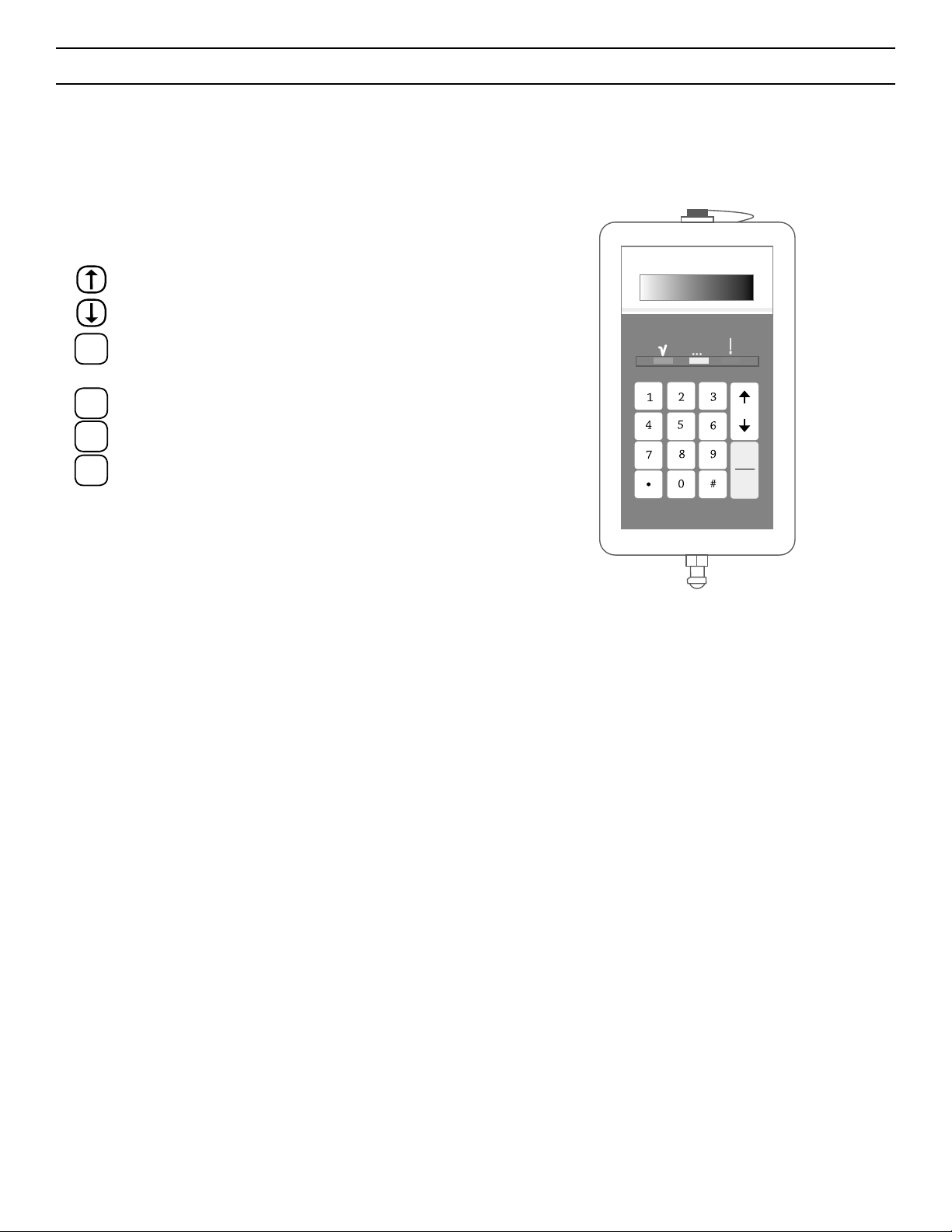
4. Description of the 101 Series Integrity Test Device . . . . . . . . . . . . . . . . . . . . . . . . . . . . . . . . . . . . . . . . . . . .5
4.1 Keyboard and screen . . . . . . . . . . . . . . . . . . . . . . . . . . . . . . . . . . . . . . . . . . . . . . . . . . . . . . . . . . 5
4.2 Connections . . . . . . . . . . . . . . . . . . . . . . . . . . . . . . . . . . . . . . . . . . . . . . . . . . . . . . . . . . . . . .5
4.3 Power On / Off Switch . . . . . . . . . . . . . . . . . . . . . . . . . . . . . . . . . . . . . . . . . . . . . . . . . . . . . . . . .5
4.4 Storage case . . . . . . . . . . . . . . . . . . . . . . . . . . . . . . . . . . . . . . . . . . . . . . . . . . . . . . . . . . . . . . 5
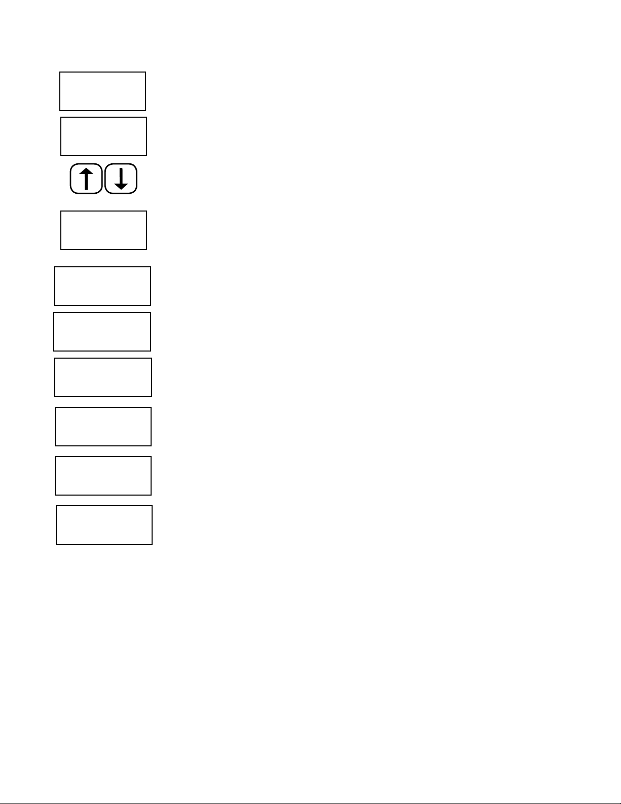
5. Diagrams of Functions . . . . . . . . . . . . . . . . . . . . . . . . . . . . . . . . . . . . . . . . . . . . . . . . . . . . . . . . . . .6
5.1 The Main Functions Menu . . . . . . . . . . . . . . . . . . . . . . . . . . . . . . . . . . . . . . . . . . . . . . . . . . . . . . .6
5.2 Service Functions. . . . . . . . . . . . . . . . . . . . . . . . . . . . . . . . . . . . . . . . . . . . . . . . . . . . . . . . . . . . 7
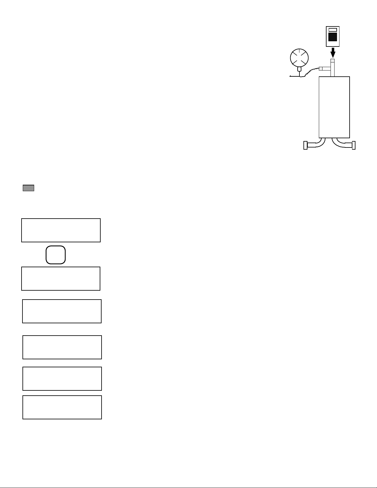
6. How to carry out an Integrity Test . . . . . . . . . . . . . . . . . . . . . . . . . . . . . . . . . . . . . . . . . . . . . . . . . . . . .8
6.1 Connecting the 101 series integrity test device to the Filter Housing . . . . . . . . . . . . . . . . . . . . . . . . . . . . . . . . . . 8
6.2 Converting the pressure units from mbar to psi. . . . . . . . . . . . . . . . . . . . . . . . . . . . . . . . . . . . . . . . . . . . . 9
6.3 Running a Pressure Hold Test (PHT). . . . . . . . . . . . . . . . . . . . . . . . . . . . . . . . . . . . . . . . . . . . . . . . . . . 9
7. Viewing Documentation . . . . . . . . . . . . . . . . . . . . . . . . . . . . . . . . . . . . . . . . . . . . . . . . . . . . . . . . . . 11
8. Selecting Other Main Menu Functions . . . . . . . . . . . . . . . . . . . . . . . . . . . . . . . . . . . . . . . . . . . . . . . . . . 13
9. Entering a Test Program. . . . . . . . . . . . . . . . . . . . . . . . . . . . . . . . . . . . . . . . . . . . . . . . . . . . . . . . . . 14
9.1 Parameter Limits . . . . . . . . . . . . . . . . . . . . . . . . . . . . . . . . . . . . . . . . . . . . . . . . . . . . . . . . . . . 14
9.2 Calculation of the Diffusion Rate . . . . . . . . . . . . . . . . . . . . . . . . . . . . . . . . . . . . . . . . . . . . . . . . . . . 14
9.3 Calculation of the Upstream Volume . . . . . . . . . . . . . . . . . . . . . . . . . . . . . . . . . . . . . . . . . . . . . . . . . 14
9.4 Entering a Test Program . . . . . . . . . . . . . . . . . . . . . . . . . . . . . . . . . . . . . . . . . . . . . . . . . . . . . . . 15
10. Printing Results . . . . . . . . . . . . . . . . . . . . . . . . . . . . . . . . . . . . . . . . . . . . . . . . . . . . . . . . . . . . . . 16
10.1. BluetoothTM Printout. . . . . . . . . . . . . . . . . . . . . . . . . . . . . . . . . . . . . . . . . . . . . . . . . . . . . . . . . 16
10.2. Viewing Data and Results using a Computer . . . . . . . . . . . . . . . . . . . . . . . . . . . . . . . . . . . . . . . . . . . . 18
10.2.1. Downloading Winfilter Software . . . . . . . . . . . . . . . . . . . . . . . . . . . . . . . . . . . . . . . . . . . . . . 18
10.2.2. Transferring Test Data and Results. . . . . . . . . . . . . . . . . . . . . . . . . . . . . . . . . . . . . . . . . . . . . 18
11. How to run Tester Auto-Test. . . . . . . . . . . . . . . . . . . . . . . . . . . . . . . . . . . . . . . . . . . . . . . . . . . . . . . . 18
12. Setting up BluetoothTM Connection . . . . . . . . . . . . . . . . . . . . . . . . . . . . . . . . . . . . . . . . . . . . . . . . . . . . 19
13. Battery Pack . . . . . . . . . . . . . . . . . . . . . . . . . . . . . . . . . . . . . . . . . . . . . . . . . . . . . . . . . . . . . . . . 22
13.1 Recharging . . . . . . . . . . . . . . . . . . . . . . . . . . . . . . . . . . . . . . . . . . . . . . . . . . . . . . . . . . . . . 22
13.2 Replacing . . . . . . . . . . . . . . . . . . . . . . . . . . . . . . . . . . . . . . . . . . . . . . . . . . . . . . . . . . . . . . 22
14. Storing the 101 Series Integrity Test Device . . . . . . . . . . . . . . . . . . . . . . . . . . . . . . . . . . . . . . . . . . . . . . . 22
15. Technical Facts . . . . . . . . . . . . . . . . . . . . . . . . . . . . . . . . . . . . . . . . . . . . . . . . . . . . . . . . . . . . . . 23
15.1 Device Features . . . . . . . . . . . . . . . . . . . . . . . . . . . . . . . . . . . . . . . . . . . . . . . . . . . . . . . . . . . 23
15.2 Device Handling TIPS . . . . . . . . . . . . . . . . . . . . . . . . . . . . . . . . . . . . . . . . . . . . . . . . . . . . . . . . 24
15.3 Maintenance Plan . . . . . . . . . . . . . . . . . . . . . . . . . . . . . . . . . . . . . . . . . . . . . . . . . . . . . . . . . . 24
15.4 Spare Parts Ordering List . . . . . . . . . . . . . . . . . . . . . . . . . . . . . . . . . . . . . . . . . . . . . . . . . . . . . . 24
16. Disposal . . . . . . . . . . . . . . . . . . . . . . . . . . . . . . . . . . . . . . . . . . . . . . . . . . . . . . . . . . . . . . . . . . 25
17. Service . . . . . . . . . . . . . . . . . . . . . . . . . . . . . . . . . . . . . . . . . . . . . . . . . . . . . . . . . . . . . . . . . . . 25
-1-

-2-
1. General
1.1 Regarding these Instructions
With these Operating Instructions, you can work with the 3M™ 101 Series Integrity Test Device quickly and safely. At the beginning of the Operating
Instructions, the Table of Contents provides an overview of all topics. In the Annex, you will find a guide for quick error diagnostics and remedies,
along with a glossary that explains all of the technical terms that are used. The index allows you to undertake a targeted search according to terms
or topics
XRead these Operating Instructions carefully and completely prior to working with the Integrity Test device.
XObserve the safety instructions in particular.
XThese Operating Instructions are included with your product. Retain this document (and all other documents delivered with the device) with
care, and keep them within reach at all times.
XWhere applicable, attach any supplement or amendment that you have received to the Operating Instructions.
XIf you lend or sell the device, you must also provide those device documents that have been supplied.
XIf these Operating Instructions are lost, you can request a replacement from 3M Purification Inc.
1.2 Symbols and signs
The following symbols and signs are used in these Operating Instructions:
This symbol indicates useful information and tips.
This symbol ´´ is placed in front of an action instruction
This symbol ´• ´ indicates an itemized list
1.3 Intended use
The 3M 101 Series Integrity Test Device is a portable filter test device for testing membrane filter cartridges for integrity within a filter housing
system.
The 3M 101 Series Integrity Test Device conforms to the directives and standards for electrical equipment, electromagnetic compatibility and the
prescribed safety regulations. However, improper use may lead to damages to persons and/or property.
These Operating Instructions have been generated in accordance with the currently used statutory provisions and guidelines. They have been
structured in such a manner that correspondingly instructed persons that are able to implement and apply those actions. Actions that go beyond
the measures described in these Operating Instructions are exclusively reserved to specialized personnel thus contact 3M Purification Inc. for as-
sistance.
Info

2. Safety Information
2.1 General
Please read, understand, and follow all safety information contained in these instructions prior to the use of this
device. Retain these instructions for future reference.
EXPLANATION OF SIGNAL WORD CONSEQUENCES
WARNING
Indicates a potentially hazardous situation, which, if not avoided, could result in death or serious injury and/or
property damage.
CAUTION
Indicates a potentially hazardous situation which, if not avoided, may result in minor or moderate injury and/
or property damage.
EXPLANATION OF SAFETY AND RELATED SYMBOLS
WARNING
Hazardous Voltage
WARNING
To reduce the risks associated with explosion and fire:
• Only use the battery pack supplied with this device. Do not replace rechargeable battery pack with non-rechargeable or unapproved battery pack. Replace only
with 3M approved battery pack.
• Do not expose device to extreme temperatures.
To reduce the risks associated with hazardous voltage:
• Do not modify or disassemble the device. Return to 3M authorized service representative for repair or service. There are no user serviceable parts.
• Do not use the device if damaged.
• Do not use power cord if device is damaged.
• Do not expose device to or in water for a long period of time. Protect device from water jets.
• Only use the SELV charger/power supply provided with the device.
CAUTION
To reduce the risks associated with impact:
• Do not connect device to a pressure source above 64 psi (4400 mbar).
To reduce the risks associated with environmental contamination:
• Dispose of device, including batteries, in accordance with applicable local regulations or laws.
IMPORTANT NOTES
XStore the device in a clean, dry place. When stored, the device should be kept in a vertical position with the compressed air connection
pointing down.
XIf fluid is introduced into the compressed air connection, it should be immediately removed
XThis device has left our factory in an error-free condition for safety purposes. It is essential that you observe the safety instructions in these
Operating Instructions, in order to maintain this condition and to ensure safe operation.
XMake sure that your device is kept clean. Check this regularly. 3M Purification Inc. offers customer service for this purpose.
XIf the device is used in a manner different from that described in these Operating Instructions, this may lead to damages to the product.
Upon such an event, if the product is misused, abused, improperly operated, etc. it will void the warranty. Use the device only in accordance
with the information in these Operating Instructions.
XAll individuals who use the device must be appropriately trained and must follow these Operating Instructions precisely.
XIf there are damages that were caused by non-observance of the Operating Instructions, it will void the warranty. 3M Purification Inc. assumes
no liability for any consequential damages that arise from this.
XNeither 3M no 3M Purification inc. is liable for any damages to its product that were caused by improperly installed, maintained or defective
devices or systems.
XSubject to technical changes without prior notice and errors.
Info
Info
Info
Info
Info
-3-

-4-
3. Introduction Principles
The 3M™ 101 Series Integrity Test Device is a small lightweight portable device used for testing the integrity of membrane filters within the filter
housing system to be used in. When testing a filter, the Operator only needs this document and does not need to know or remember any of the
testing parameters. Test parameters are entered into the test device program memory once and whenever a test is performed. The test device LED
screen displays the test pressure and instructs the operator when to close the pressure valve following stabilization. The pressure hold test will stop
automatically when the test is complete indicating a result by means of colored LEDs. Each filter test carried out is automatically saved into the test
device memory allowing the operator to recall the results of the test on either the display screen or to print a hard copy by either connecting the unit
to a PC with the mini-USB cord or wireless via a BluetoothTM compatible printer.
The 3M 101 series integrity test device has been designed to test a variety of membrane filters. The unit can be programmed up to 19 individual
test protocols.
The 3M 101 series integrity test device is a semi-automatic “intelligent” precision pressure gauge, with a data storage memory. Due to the size of
the Integrity Tester, it does not have an integral valve for automatic pressure adjustment; consequently it is not completely autonomous, signaling
the operator with text and indicator lights to make a manual adjustment when needed.
During the integrity test, the 3M 101 series integrity test device
takes a very precise pressure measurement. It measures the pres-
sure drop within the housing during the test time and calculates the
diffusion rate based on the pressure drop and the upstream volume
of the housing.
The calculation is based on the following principles :
The filter system is pressurized on the up- stream side to a pres-
sure P1. The housing / filter combination has a known upstream
volume of V1(Figure 1). At the beginning of the test, the upstream
pressure source is isolated and the downstream P1left open to
ambient. During the test, gas will diffuse from the pressurized
upstream side of the filter to the ambient downstream side. This
diffusion will be calculated from the decrease in the upstream pres-
sure P2. The volume of gas lost due to diffusion V2can be calcu-
lated (Figure 2) as follows:
Total volume of gas initially in the filter system :
C = P1x V1
The energy of the gas remaining in the upstream volume after the test plus the lost energy due to diffusion through the filter.
C = (P2x V1) + P0x V2Where P0is ambient
Because P1and P2can be measured, V1and P0are known then V2can be determined with the following calculation:
V2= (P1- P2) x V1
P0
To calculate the diffusional flow rate mL/min:
Diff = V2
Test time (min)
Any temperature fluctuation will affect the accuracy of any pressure measurements and the diffusional flow rates. It is important that neither the
ambient temperature nor the temperature of the source gas fluctuate during the test period. Testing should not be carried out immediately follow-
ing steam sterilization of the filter system but only after the housing has cooled to ambient temperature. It is further recommended that testing be
performed under normal environmental conditions and temperature extremes are avoided during the testing period.
NOTE: Diffusional flow rate calculations from the measured change in pressure, the Integrity Tester assumes the temperature is at a constant 20 °C
and that the atmospheric pressure does not vary from 14.5 psi (1000 mbar).
Volume
V1
Pressure
on P1
P1
Pressurized Filter System
Volume
V1
Pressure
on P2
Ambient Pressure
P0
Diffused Gas
P0* V2
Figure 1 Figure 2

4. Description of the 3M™ 101 Series Integrity Test Device
4.1 Keyboard and Screen
Indicator lights provide the user a visual indication of the result of the test or prompt the user to the next step:
A GREEN light indicates a positive or pass test result.
A YELLOW LED light indicates that the Integrity tester is busy and the user must wait for the next step.
A RED light indicates a negative or failed test result or asks the user to go on to the next step.
The keyboard is comprised of 6 function keys and 10 number keys:
RNext Step
RPrevious Step
Start Start a new function,”Proceed”, “Yes to a question”
Stop Finish a function
*Special function, if indicated on the screen
#Special function, if indicated on the screen
0...9 Number input
4.2 Connections
The compressed air quick connect is located at the bottom of the device and ensures that any humidity that may have been introduced with the
compressed air is able to escape.
The data connection mini-USB port is located at the top of the device and is protected by a hermetic cap. The mini-USB port allows the device to
connect to a PC by means of a data transmission cable with mini-USB and USB connectors to enable test results to be downloaded and stored.
The 101-Series Integrity Test Device has BluetoothTM capability to allow transmission of test data and results to a Bluetooth compatible printer.
The device charging socket allows recharging of the device.
4.3 Powering On/Off the device
Press the “START” key pad to turn on and press & hold the “STOP” key pad to turn off the device.
4.4 Storage case
The storage case helps protect the 3M™ 101 Series Integrity Test Device from everyday wear and tear. It is recommended that precautions are
taken to ensure that the unit is not exposed to high voltage electrical appliances and is protected from prolonged exposure to high humidity and
mechanical load. (See Technical specifications)
-5-
Figure 3
START
STOP
LED Indicators lights
Keyboard
Compressed Air connector
Display
Hold START to
turn ON
Hold STOP to
turn OFF
START
STOP
*
#

-6-
5. Diagrams of Menu Functions
5.1 The Main Functions Menu
This menu group consist of six main upper level functions that includes all functions needed to program a filter test, execute a filter test, program
various parameters and management of test results.
Screen prompts:
This function allows the user to select and review stored test protocols.
Use “Up Arrow” and “Down Arrow” keys to move between menu functions and to advance to next step or
return to the previous step.
This function allows the Operator to Recall Test Results, and view them on the LED screen.
This function allows the Operator to print test results.
This function allows the Operator to create up to 19 individual test programs, entering test parameters that
define each filter tests. This function can be switched off through the device configuration
This function allows the Operator to change between summer and winter time. Press start, then “*“ to
change between winter and summer options. (To change the time of day, use the SERVICE menu function.)
With the SERVICE function, the Operator can access the service functions menu. These service functions are
not necessary for everyday use of the 101-Series Integrity Test device.
Press the “START” key to select a specific function, proceed to the next step or answer “YES” to a question.
By pressing the “STOP” key, the function can be stopped, the test can be aborted or the Operator can select
another main function.
>
↓↑
>
↓↑
>
↓↑
TEST RESULTS ?
TEST RESULTS ?
TEST RESULTS ?
>
↓↑
PROCEED >
↓↑
PROCEED > ↓
↑
TEST FILTER ?
SERVICE ?
PROCEED
SET CLOCK ?
PROCEED
TEST PROGRAMS ?
PROCEED
PRINT DATA ?
PROCEED
TEST FILTER
PROCEED >
TEST RESULTS?
PROCEED >
PRINT DATA?
PROCEED >
TEST PROGRAM?
PROCEED >
SET CLOCK?
PROCEED >
SERVICE?
PROCEED >
START
STOP

-7-
5.2 Service Functions
The group of service functions allows changing and verifying specific parameters.
To enter the Service Functions menu press the “#” key when “SERVICE ? PROCEDED > is displayed.
When prompted enter “ 7” as the security code.
The Service Functions Menu can now be accessed using the up and down arrows.
Use the “scroll up arrow” to move to the next step.
Use the “scroll down arrow” to return to the previous step.
This function is used to change the time and date.
This function is used to calibrate the 3M™ 101 Series Integrity Test device within defined limits.
NOTE: The pressure transducer is factory calibrated and should only be calibrated by a trained technician.
This function allows the Operator to choose the language (English, French, German, Italian or Spanish).
This function is used to request information concerning important operating parameters.
The factory programmed access code is 7, this function allows the Operator to modify the access code with
up to a five-digit numerical code to allow access to the Service Functions Menu.
This function erases all of the 3M 101 series integrity tester memory. The function is normally only used
before a complete recalibration.
NOTE: Test programs, results and calibration data will be erased.
SERVICE?
PROCEED >
*SERVICE*?
PROCEED >
CLOCK SET?
PROCEED >
CALABRATION?
PROCEED >
LANGUAGE?
PROCEED >
INFORMATION?
PROCEED >
ACCESS CODE?
PROCEED >
CONFIGURATION?
PROCEED >
ERASE DATA ?
PROCEED >
Here you can set, or activate or deactivate, the device functions:
• Selection of the mbar/psi pressure unit
• Prompt for a user ID ON/OFF: the user ID is requested prior to the start of a filter test.
• Prompt for a TEST ID ON/OFF/ automatic allocation: the test ID is a number that is
allocated for each test.
• Entry of ON/OFF parameter: activates the TEST PROGRAM function in the Main Menu.
• Entry of ON/OFF/FULL clock: activates the TIME function in the Main Menu.
• OFF: no access to the time in the main functions
• ON: only displays time, switching to summer / winter time
• FULL: full access to adjustment of date and time
• Entry of BluetoothTM mode 0-3
0: Bluetooth off
1: Bluetooth function, no additional instructions
2: Bluetooth function, general instructions (normal setting)
3: Bluetooth function, all instructions

-8-
In this function, please read off the pressure measurement without performing a filter test Records the num-
ber hours the unit has been in operation.
Print out all of the device-specific data regarding the Bluetooth printer.
Note the instructions regarding the Bluetooth printer
In order to be able to use the Bluetooth printer, a connection to the printer must have been created and
saved. Establish a new Bluetooth connection through this function.
If a connection already exists, the Bluetooth address of the printer is displayed.
Note the instructions regarding the Bluetooth printer.
The START key allows the Operator to call up the function chosen.
The STOP key, allows the Operator to end a service function and exit the Service functions menu. Press the
STOP key several times to return to the main functions menu.
This function is used to calibrate the 3M™ 101 Series Integrity Test device within defined limits.
NOTE: The pressure transducer is factory calibrated and should only be changed by a trained technician.
• Entry of beeper 0-2
0: beeper off
1: normal beeper function (normal setting)
2: extended beeper function for all memory operations.
• Entry of display timer
0: timer function off
1-60: automatic switch-off time after the last key entry, in minutes
• Entry of auto-off timer
0: timer function off
1-60: automatic switch-off time after the last key entry, in minutes
• Entry of calibration interval in months
• Entry of maximum deviation of the test pressure at the beginning of the test
MANUAL OPERATION ?
PROCEED >
SERVICE PRINT ?
PROCEED >
BLUETOOTH ?
PROCEED >
START
STOP
6. How to carry out an Integrity Test
6.1 Connecting the 3MTM 101 Series Integrity Test Device to the Filter Housing
The 3M Series Integrity Test Device can be connected directly to the housing with a regulated compressed air source and tee. It is important that the
3M Series Integrity Test Device stay vertical so that any water accidentally introduced with the compressed air system cannot enter the 3M Series
Integrity Test Device and penetrate the electronics with in the device. See Figure 4 on the next page.
NOTE: When running an integrity test, make sure that the pressure used to fill the filter housing does not exceed the maximum diffusion test pres-
sure of the test filter, device, and the housing.
To prevent measurement errors, follow the following recommendations: - Do not exceed maximum operating pressure (see technical specifica-
tions), avoid sudden bursts of pressure
CAUTION
• To reduce the risks associated with impact: Do not connect device to a pressure source above 64 psi (4400 mbar).
- Use only clean, dry, oil free, filtered compressed air or nitrogen
- Drain the filter housing before connecting the 3M Series Integrity Test Device , this prevents the possibility of any water penetration.
- Install the Integrity Tester to be a vertical, upright position as shown in Figure 4 on the next page.

-9-
6.2 Converting the pressure units from mbar to psi
NOTE: The 3M™ 101 Series Integrity Tester is sold with pressure units programmed in mbar. To convert the pressure
units displayed in psig, execute the following procedure:
1. After the Integrity Tester has been turned on, press the START key.
2. Using the Up Arrow key select “SERVICE ?”.
3. Enter the Service menu by pressing the “#” key.
4. When requested, enter security code “7”.
5. Using the Up Arrow key, select “configuration ?” and press the START key.
6. You will now be able to change the pressure units to psi by pressing the “ * ” key.
7. Using the Up Arrow key, select * SERVICE * and press the STOP key to return to the main functions menu.
6.3 Running a Pressure Hold Test (PHT)
The 3M 101 Series Integrity Tester will determine whether the entire filter system (housing and piping) has any leaks
and whether or not the installed filters are structurally integral. Before testing the filter, the filter cartridge must be
fully wetted. (Follow 3M Purification’s recommended wetting conditions for the grade of filter installed.) It is impor-
tant the operator ensures that the whole surface of the membrane is wet. When wetting out of the filter has been
achieved, open the upstream and downstream housing drain valves to drain the housing of excess water.
When the 3M 101 Series Integrity Test Device is first turned on, the display will provide displays ‘CONTINUE: *
Info The keyboard entries and screen texts describe below show the operational sequence in the standard version of the product.
Connect the 3M 101 Series Integrity Test Device to the housing to execute the test. See Figure 4.
0
1
2
3
4
Figure 4
Info
Immediately after switching on, the device is in the beginning of the FILTER TEST function.
Press START.
Appears only if activated in CONFIGURATION:
Enter your user code ID (up to a 4 digit numerical code numbers can be used)
If the test program number to be run is displayed.
If the displayed test program number is incorrect, enter correct test program number. The
number selected will replaces the displayed number
If you have selected a program that has not yet been defined, the "not defined" indicator appears.
“filter unknown” will be displayed if the program number selected has not been previously programmed into
the 3M 101 Series Integrity Test Device.
For the following steps connect the 3M 101 Series Integrity Test Device to the housing, then press START
KEY to begin executing the test.
If there is no pressure on the filter, the 3M 101 Series Integrity Test Device indicate to the Operator to open
the compressed air connection valve. The red LED will flash as the pressure increases.
TEST FILTER ?
PROCEED >
USER CODE ?
PROCEED >
START
TEST PROGRAM NO 12
PROCEED >
TEST PROGRAM NO
UNKOWN >
START TEST?
>
PRESSURE?
10.00 PSI

-10-
The pressure required for the test is displayed. The yellow LED flashes. Manually adjust the pressure at the
filter system. As soon as pressure is detected, the indicator moves to the next step.
Manually adjust the pressure at the filter system. If the pressure is outside the tolerance thresholds, the
device indicates “CAUTION - DEVIATION!” Adjust the pressure so that it is within the tolerance thresholds. You
can adjust the tolerance thresholds in the configuration.
As soon as the pressure is within the tolerance thresholds, the operational sequence of the stabilization
period starts automatically and the remaining time is displayed.
NOTE: As the test pressure is approached, slowly and carefully adjust the pressure applied to the housing.
DO NOT exceed the test pressure to be used by more than + 1.435 psi (+ 99 mbar). If the test pressure
is exceeded by 1.435 psi (99 mbar) and not adjusted prior to beginning of the test, the final result will be
displayed as a “FAIL” even if the measured result is less than the maximum PHT limit. The tester recognizes
that the correct test pressure has been reached and automatically initiates the stabilization phase.
During stabilization, the pressure reading is the actual pressure to the housing. If the reading is > + 1.435
psi (+ 99 mbar), the pressure to the housing can be reduced as long as it is reduced and stable BEFORE the
end of the stabilization periods. During stabilization, the yellow LED is illuminated indicating “please wait”.
The elapsed time is displayed in seconds.
Stabilization time can also be shortened by pressing the arrow key
Once stabilization time has finished, to continue with the test, close the connected compressed air supply.
Press START key to proceed.
Thereafter, the filter test starts automatically if the pressure is within the tolerance thresholds
The tolerance thresholds are set in the device configuration.
While the filter test is running, the remaining time is shown. With the * key, you can access alternative mea-
sured values, such as pressure drop/min or diffusion ml/min. While the test is in-progress, the yellow LED is
illuminated indicating “please wait”. The pressure decay and test time are displayed.
Alternative measured values are calculated and displayed only after 30 seconds
The test result is displayed at the end.
PASS: filter test passed, diffusion within maximum value.
FAIL: filter test not passed, diffusion outside of the PHT test limits, a red LED will flash.
ABORT: filter test was manually aborted, or automatically aborted through a large pressure drop. Test can be
interrupted by pressing the STOP key, the yellow LED will flash.
PRESSURIZE 10 PSI
STAB-TIME 55 SEC
COMPRESS AIR
SWITCH OFF?
START
FILTER TEST
SELECT WITH*
TEST TIME 50sec
DIF. 0.7 ml/min
RESULT PASS
>

-11-
7. Viewing Documentation
Start the TEST RESULTS function.
Using the arrow keys, you can scroll and choose a test log. Search forward or backward for a particular test.
There are up to 150 tests in the memory. The date, time and ID code of a test (if activated in the configura-
tion) are displayed
With the # key, you can switch to the last test that was performed
With the START key, the test is displayed
The test data follow. Press any key (except STOP) to display other values measured.
The device displays the ID code entered for measurement.
Date and time of a test are displayed.
Date and time of test was performed.
The evaluation of the selected test is displayed:
PASS: tested system passed integrity test.
FAIL: tested system failed integrity test.
NOT CARRIED OUT: test was not carried out.
The number of the applied test program and the specified filter type are displayed
Type of test is displayed
Test diffusion rate is displayed
Using the * key, you can access other values:
- Pressure drop overall, a negative value signifies a pressure increase
- Pressure drop/min
- Diffusion rate
TEST RESULTS?
PROCEED >
TEST RESULTS?
PROCEED >
3/18/2014 18:00
TEST ID 7
#
START
TEST DATA
>
USER CODE
55 >
DATE 29.01.2014
TIME 17:52
RESULT
PASS >
TEST PROGRAM Nb. 1
01x10“0.20 >
TEST-METHOD
PRESSURE DROP TEST
DIFFUSION RATE
10.0ml/min
#
0.0ml/min
OTHER VALUES *

Using the arrow keys, you can continue scrolling through the various results of a test.
The pressure value at the start of the stabilization period.
Displays the actual stabilization period.
Displays the test pressure at the start of the filter test.
Displays the actual test period.
Displays the entered air pressure (see Service Menu). The air pressure value has a minor influence on the
measurement results, and is therefore documented.
The following additional information on the filter stored in the program follows:
Filter type, filter batch, filter series, housing, fluid type and the filter parameters.
Tested filter lot number displayed.
Tested filter serial number displayed.
Test housing type displayed.
Test fluid type used for test is displayed.
At this point, using the (X) arrow keys will displays entered test parameters of the selected performed test.
Using the arrow keys, you allow you to scroll.
Search forward or backward for a particular programmed test parameters used.
Programmed stabilization time.
RESULT
Pass >
STABILIZATION TIME
60 sec
TEST PRESSURE
10.17 psi >
TEST TIME
120 sec >
ATMOSPHERIC
PRESURE 14.70 psi
FILTER TYPE
01x10“0.20 >
FILTER LOT
45
FILTER SERIAL N0
55
HOUSING
1
FLUID TYPE
WATER
FILTER PARAMETERS
STABILIZATION
PRESSURE 12.00 PSI
STABILIZATION TIME
60 sec
-12-

-13-
Programmed test pressure.
Programmed test time.
Programmed test cartridge diffusion rate at above pressure.
Programmed test system upstream volume.
Programmed test cartridge quantity.
TEST PRESSURE
12.00 psi
TEST TIME
120 sec >
DIFFUSION RATE
60.0ml/min
UPSTREAM VOLUME
1860 ml
NO. OF CARTRIDGES
1
8. Selecting Other Main Menu Functions
After being switched on, the 3M Series Integrity Test Device first calls up the filter test function. To carry out another function, the operator must
first halt the current filter test program.
Device display indicates it is at test function program #1.
Press STOP to exit current programming activity.
Return to the main function menu.
TEST PROGRAM NB 1
ENTER >
TEST PROGRAM ?
PROCEED >
STOP

-14-
Parameters Permitted data range
Program number (no. of test program) 1-19
Pore size 0.1 µm– 2.00 µm
Maximum diffusion rate per cartridge 0.1 ml/min – 999.0 ml/min
Number of cartridges 1 – 99
Test pressure 0.71 psi (50 mbar) – 60 psi (4,100 mbar)
Stabilization period 30 sec – 1,800 sec
Test period 30 sec – 1,800 sec
Upstream Volume of the housing 10 ml – 999,999 ml
Filter type Enter max. of 20 numeric characters only*
Filter batch Enter max. of 20 numeric characters only*
Filter series Enter max. of 20 numeric characters only*
Housing Enter max. of 20 numeric characters only*
Fluid type Select one of three fluid type options
Note: * Can only enter numeric values using device. Using Winfilter 3.01 software enables, alphanumeric values can be entered
9.2 Calculation of the Diffusion Rate
When the Operator is programming the Integrity tester to run an integrity test, the test limit must be calculated. The maximum diffusion rate
for a cartridge must be determined and entered into the test program. The 3M 101 Series Integrity Test Device provides the maximum diffu-
sion rate limit for each filter grade per 10” filter element. For longer length filter cartridges, this diffusion rate per 10” filter element must be
multiplied:
Diffusion rate = diffusion rate limit per 10” filter cartridge x number of 10” cartridges in the installed
Housing. For example:
Calculation for a 20” cartridge is: maximum diffusion rate = FFIT limit value per 10” cartridge x 2
Calculation for eleven (11) 30” cartridges is: maximum diffusion rate = FFIT limit value per 10” cartridge x 33
9.3 Calculation of the Upstream Volume
The following two methods are used to assess the upstream volume of a system:
1. Install the filter cartridges to be tested into the filter housing. Flush the system with ambient temperature water in accordance with the
manufacturer’s recommended flushing conditions, ensuring that any entrapped air is removed from the housing by venting the housing
during this flushing step. Close the housing vent valve after all the trapped air has been released from the housing. After the recom-
mended flush volume and time, close the upstream water inlet valve. Place a suitable sized container under the upstream inlet drain
valve of the filter housing, open the upstream drain valve and collect the water that runs out when the housing upstream vent valve is
opened. Weigh the amount of water collected and calculate the upstream housing volume.
2. Manually measure the housing and calculate the volume as if the housing was a cylinder. Measure and calculate the volume of inlet
piping from the upstream shut off value to the housing inlet and add this value to the calculated housing volume. Measure and calcu-
late the volume occupied by a cartridge, multiply the value by the number of cartridges and subtract this value from the housing and
piping volume calculated.
3. For help, contact your 3M Purification Inc. representative.
9. Entering a Test Program
9.1 Test Parameter limits
The 3M™ Series Integrity Test Device can create and store 19 different test programs for the testing of 19 different filter / housing combina-
tions. For this purpose, you must enter the data for your system in the device.

9.4 Entering Test Program
Programming may be performed manually on the device, or with the assistance of the WinFilter3.01 software. Programming through WinFilter3.01
is particularly much easier regarding the entry of model numbers and series numbers, and is therefore recommended.
Notes:
• The entry arrow appears bright if an entry is not in the valid range. As soon as the entry is in the valid range, the arrow appears black.
• Entries may be deleted with the “#” hash key.
-15-
Start the TEST PROGRAMS function.
Enter the desired program number between 1 and 19, e.g. 3.
The program number is displayed .
Enter the parameters shown in the following. Note the limits provided in the above table.
A filled triangle (X) in front of the value indicates that the value is within the valid range. Otherwise, an
empty triangle is displayed.
Using the # key will delete a value.
Enter the diffusion rate per filter cartridge. If filters are larger than 10" is used, multiply the diffusion rate by
the number of 10" modules per filter.
Enter the maximum value according to your test cartridge product brochure.
If different cartridge sizes are contained in the filter, you can also indicate the total value of the diffusion rate
and only one cartridge here.
Indicate how many cartridges are included in the housing to be tested.
Enter the test pressure according to the data sheet for your filter.
Enter the stabilization period.
Enter the test period.
TEST PROGRAMS ?
PROCEED >
TEST PROGRAM NO. 1
PROCEED >
TEST PROGRAM NO. 3
PROCEED >
START
START
PORE SIZE
X0.33 µm >
DIFFUSION RATE
PER CARTRIDGE >
PER CARTRIDGE
MAX X20.0ml/min
PER CARTRIDGE
MAX X20.0ml/min
TEST PRESSURE
X12.00 psi >
STABILIZATION TIME
X180sec >
TEST TIME
X300sec >

-16-
Enter the net upstream volume of the housing. Note that hoses and other external components, along with
the filter cartridges, must be taken into account.
Entering a filter type can facilitate the identification of the test program With the * key, you can reset the filter
length: Display format: Number of cartridges x cartridge length (inches) x pore size. You can edit the value
for cartridge length using numerical keys. With the # key, you can delete the entry. With the WinFilter3.01
software, you can enter any text here.
Here, you can enter the filter lot number as a pure numerical value using the keypad, or as any text with the
WinFilter3.01 software.
The entry is possible only as pure numerical values, or as any text with the WinFilter3.01 software.
Using the * key, select among the pre-programmed fluid types (water, IPA/water, and product) or use the
WinFilter3.01 software for any text entry.
The following displays will provide calculated test parameters.
The overall diffusion rate of all filter cartridges.
The maximum permitted pressure drop per minute of testing filters.
Returned to main menu.
UPSTREAM VOLUME
X10100ml
FILTER TYPE
02x00”0.33 >
FILTER-LOT
3 >
FILTER SERIAL NO.
3 >
HOUSING 13
>
FLUID TYPE
WATER >
PROGRAM TEST
CALCULATED >
DIFFUSION RATE
MAX 40.0ml/min
PRESSURE DROP
MAX 0.880 psi/min
TEST PROGRAMS ?
SELECT WITH * >
10. Printing Results
10.1 Bluetooth Printout
The direct print-out of the test data takes place wirelessly through a Bluetooth printer, that is available as an accessory with the 3M™ 101
Series Integrity Test Device.

-17-
Notes:
In order to be able to print via BluetoothTM, the Bluetooth setting must be activated in the Service Menu in the CONFIGURATION function. For this
purpose, set the Bluetooth mode value to 2, as described on page 7.
In addition, a connection to this printer must be created and saved in the BLUETOOTH function. If a connection to a printer has been created once,
it will be automatically established as soon as the printer and the filter test device are switched on. If the printer or the device is switched off, the
Bluetooth connection is terminated. The Bluetooth connection requires that the printer is located in close proximity (a few meters) to the filter test
device.
Printer functions can be accessed only when the Bluetooth connection is active. If the Bluetooth connection is broken, you receive a “PRINTER NOT
READY” display.
Strong radio signals or other Bluetooth transmitters can interfere with the connection. Therefore, it is best to disable Bluetooth devices that could
interfere with the connection.
Start the PRINT DATA function from the Main Menu. With this function, you can print a test log in conjunction
with the Bluetooth printer.
Press the START key to start printing.
Using the arrow keys, find the first data record in the data memory that is to be printed.
Press the START key to select the first data record that is to be printed.
Now, using the arrow keys, find the last data record that is to be printed.
Press the START key to select the last data record that is to be printed.
The display window shows the number of data records printed
Start the print-out with the START key.
PRINT DATA ?
PROCEED >
FIRST DATA SET
SELECT WITH >
START
START
START
1 DATA SETS PRINT
DATA SETS ARE BEING
PRINTED…
START

-18-
10.2 Viewing Test data and Results using a Computer
10.2.1 Downloading Winfilter Software to a Computer
In order to view program settings, data and results on a computer, the Winfilter 3.01 version software needs to be installed on the computer. For in-
stallation, place the provided CD disk containing the Winfilter 3.01 and all support software in the computer CD drive, follow all instructions provided
on the computer during the installation process. Upon completion of the program installation, a Winfilter 3.0 icon will appear on computer desktop.
10.2.2 Transferring Test Data and Results to a Computer
Using provided USB (A Type) & USB mini-b cable, connect the 101-Series Integrity Test device to a computer with the installed Winfilter 3.01 data
backup program. Turn on the 101-Series Integrity Test device. Access the Winfilter program by either clicking on the computer desktop Winfilter
icon (or the Windows icon accessing computer program directories). The Winfilter3.01 program allows you to program, transfer, view and print test
program parameters, test data and results.
Notes:
If you have carried out a data backup, all data in the device are preserved, but are marked therein as backed up. Thus, they are approved for being
overwritten with new data, without requiring the appearance of a warning message. The memory is thus once again freely available.
Info - Data Loss!
Perform the data backup as soon as possible, when you receive a warning message from the device that only ten, or fewer than ten, free memory
locations are available. If the memory is full, the device starts to overwrite the oldest data with new measurements. Thus, the oldest data is gradu-
ally lost.
Info
11. How to run Device Auto-Test
The 3M™ 101 Series Integrity Test Device performs constant monitoring of the most important operating data. If an error arises, it is reported
immediately.
The device displays important error messages, such as leaks in the filter, until the user confirms them by pressing any key. Non-critical error
messages are automatically hidden after eliminating the cause of the error.
Based on the following table, you can isolate the possible errors that arise, along with the possible causes. If only specialized personnel can
resolve an error that arises, this is noted in the “Remedy” column: “Contact 3M Purification Customer Service”.
Error Cause Remedy
Warning message:
Battery pack is nearly empty Charge battery pack
Battery pack nearly empty
Error message:
Charge battery Battery pack is empty Connect power supply and charge battery
pack
The battery is running out quickly Battery pack is aged Change battery pack
Error message:
Overpressure
The pressure is greater than the specified
measurement range! As it increases further,
the device may be damaged.
Reduce applied pressure
Calibration parameters, measurement error
In the Service Menu:
1. Check calibration parameters
2. Contact 3M Purification Customer Service
Pressure sensor not operating correctly Contact 3M Purification Customer Service

-19-
Error Cause Remedy
Error message: Pressure sensor
Calibration parameters:
Offset and/or reinforcement incorrect
In the Service Menu:
1. Check calibration parameters, and (if neces-
sary) recalibrate
2. Contact 3M Purification Customer Service
Pressure sensor not operating correctly Contact 3M Purification Customer Service
Defective pressure measurement
Pressure sensor not operating correctly Contact 3M Purification Customer Service
Calibration parameters:
Offset and/or reinforcement incorrect
In the Service Menu:
1. Check calibration parameters and (if neces-
sary) recalibrate
2. Contact 3M Purification Customer Service
Filter test does not start
Empty test program selected Select a test program with valid test
parameters
Test parameters are invalid Recharge batteries (see Manual). Re-enter test
parameters.
Pressure is outside of tolerance Check test pressure
Test programs and documentation data are
invalid, due to defective buffer battery Contact 3M Purification Customer Service
Time/date is incorrect Time/date is not valid, due to empty buffer
battery
Recharge battery (see Manual) and readjust
time and date in the Service Menu
Integrity Device does not switch on
Battery pack is empty Charge battery pack
Battery pack is not operating correctly Replace battery pack
Fuse is not operating correctly Contact 3M Purification Customer Service
Red charging LED does not blink when charg-
ing battery pack
Defective power adapter Replace power adapter
Fuse is not operating correctly
Red charging LED is blinking rapidly Charging function was aborted Remove charging plug and insert again
No access to the Service Menu Wrong security code entered Enter correct security code. Ask your service
technician.
12.- Setting Up BlueTooth Connection
To be able to print via Bluetooth, a wireless link between the 3M™ 101 Series Integrity Test Device and the Bluetooth printer needs to be
established. Using the BLUETOOTH function in the submenu of the Service function of the 3M 101 Series Integrity Test Device allow setting up
and save the printer BLUETOOTH code. The Bluetooth connection requires that the printer is located in close proximity (a few meters) to the
filter test device.
Note: Strong radio signals or other Bluetooth transmitters can interfere with setting up the connection between devices. Therefore, it is best to
disable Bluetooth devices with the immediate area that could interfere with the connection
Table of contents
Other 3M Test Equipment manuals

3M
3M Clean-Trace AQF100 Instruction sheet

3M
3M FT-10 User manual

3M
3M 740 User manual

3M
3M Wireless Tire Pressure Monitoring System User manual

3M
3M PS200 Series Manual

3M
3M 740 User manual

3M
3M Dynatel 965AMS-BT User manual

3M
3M 701-L User manual

3M
3M Attest Super Rapid Readout Biological Indicator... User manual

3M
3M Dynatel 2273ME Series User manual