3M Charge Analyzer 711 User manual

User’s Guide
3M™Charge Analyzer 711

2
Table of Contents
Section Page
Safety Information ................................................................................................3
1.0 General Function and Description...............................................................5
2.0 Accessories..................................................................................................7
3.0 Specifications ..............................................................................................8
4.0 Fieldmeter Operation...................................................................................9
5.0 Voltmeter Operation ..................................................................................11
6.0 Static Decay Time & Balance Operation...................................................15
7.0 3M™ Remote Field Sensor Probe 711RS Operation..................................20
8.0 Data Recording and Analog Outputs.........................................................23
9.0 Verification Procedure ...............................................................................23
10.0 Maintenance/Calibration/Repair of 3M™Charge Analyzer 711 and
3M™ Remote Field Sensor Probe 711RS...................................................25
Regulatory Information......................................................................................26
Warranty.............................................................................................................27

3
Safety Information
Read, understand, and follow all safety information contained in this User’s
Guide prior to use of the 3M™Charge Analyzer 711. Retain this User’s Guide for
future reference.
Intended Use
The Charge Analyzer 711 is intended for use in testing the performance of static
control products.
This device is designed for use as specified in the operating instructions. It is
intended for use in an indoor environment and has not been evaluated for other
uses or locations.
Explanation of Signal Word Consequences
DANGER:Indicates a potentially hazardous situation, which, if not avoided, will
result in death or serious injury and/or property damage.
WARNING:Indicates a potentially hazardous situation, which, if not avoided, could
result in death or serious injury and/or property damage.
CAUTION:Indicates a potentially hazardous situation, which, if not avoided, may
resultin minor or moderate injury and/or property damage.
CAUTION:Indicates a potentially hazardous situation, which, if not avoided, may
result in property damage.
Explanation of Product Safety Label Symbols
ATTENTION:Read accompanying documentation
WARNING:Risk of Electric Shock
GROUND
SYMBOL: Ground device according to instructions.
To reduce the risks associated with hazardous voltage, which if not avoided, could result in death or
serious injury:
• Connect the attached ground wire on the rear panel to an electrical ground before operating.
• Refer to 3M™Charge Analyzer 711 User’s Guide
WARNING

4
To reduce the risks associated with hazardous voltage:
• Connect the attached ground wire on rear panel to an electrical ground before operating the Charge
Analyzer 711;
• Do not use if the 3M™Charge Analyzer 711 housing or power supply are damaged;
• Do not attempt to modify or repair – no user serviceable parts inside – contact 3M Service for repair.
To reduce the risks associated with fire or explosion:
• Do not operate the Charge Analyzer 711 in an explosive environment. The Charge Analyzer 711 is not
designed to be intrinsically safe.
WARNING
To reduce the risks associated with use of alcohol for cleaning:
• When cleaning the Charge Analyzer 711 per the operating instructions, follow the MSDS procedures for
safe use of the required cleaning solution.
To reduce the risks associated with environmental contamination from the NiMH battery pack and
circuit boards containing lead-bearing solder:
• The Charge Analyzer 711 contains a NiMH battery pack and circuitry that contains lead in the solder. At
the end of service life, dispose of the Charge Analyzer 711 in accordance with federal, state and local
requirements.
CAUTION
To reduce the risks associated with property damage due to improper repair or modification:
• Do not attempt to modify or repair – no user serviceable parts inside – contact 3M Service for repair.
To reduce the risks associated with property damage from improper maintenance:
• Unit must be cleaned and checked periodically for correct operation.
CAUTION
• Avoid extreme discharge of the rechargeable batteries. If the batteries require charging, do not allow
the unit to sit idle for a period of time without first fully charging the batteries.
• Do not use the Charge Analyzer 711 or 3M™Remote Field Sensor Probe 711RS in areas where high
AC or DC field strengths are present.
• Do not discharge to the sensor element of the Charge Analyzer 711 or Remote Field Sensor Probe 711RS.
• Do not allow any object to contact the sensor elements. Permanent damage to the sensor elements
may occur. When not in use, keep sensor heads protected with supplied covers.
IMPORTANT NOTES

5
1.0 General Function and Description
The 3M™Charge Analyzer 711 is an electronic test
instrument designed for ease of use. The lightweight
and compact construction offers great versatility
in the workplace. It can be used as a laboratory
analytical tool, evaluating the performance of ionizing
equipment, static-protective packaging, worksurfaces
and personnel grounding systems. It is also very
effective for use as a demonstration tool in employee
static awareness training programs.
All parameter settings are controlled via a built-
in EEPROM. These parameters are defaulted to when the Charge Analyzer
711 is switched on again. In case of a malfunction, the unit will display a
corresponding message and then automatically switch off.
The Charge Analyzer 711 operation works according to the fieldmill-principle.
The fieldmeter is a parametric amplifier. An electrostatic field induces a charge
on the sensor electrode, generating an AC current that is proportional to the field
strength. An amplifier measures this current without reducing the energy of the
electrostatic field in average time.
The Charge Analyzer 711 is powered by built-in
rechargeable NiMH-batteries or an AC wall plug-
in adaptor. When the unit is powered from the
rechargeable batteries, the LCD-display will not be
back illuminated to extend battery life. This power
saving feature will initiate within 60 seconds after
the last measurement or button depression. Also
during battery operation, the continuous LED-bar
indication changes to a single (momentary) action.
In case of a low battery power condition, the Charge Analyzer 711 automatically
switches off, first displaying LOW BATTERY then SWITCHING OFF UNIT. If
this occurs, continued operation of the Charge Analyzer 711 can be maintained
through the AC adaptor. Recharge time is approximately 14 hours with unit off,
when batteries are fully discharged.
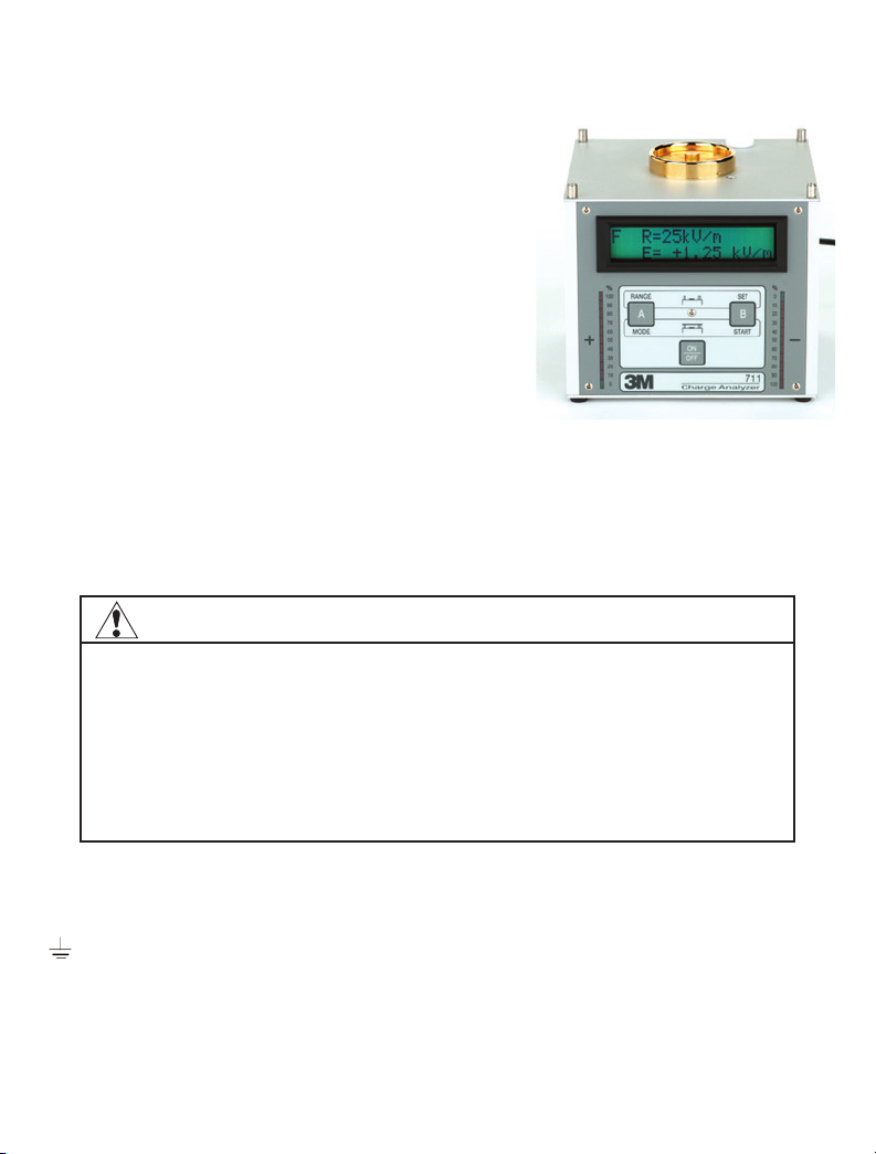
Two vertical LED bars indicating 0 - 100% charge level and polarity are located
on the left and right sides of the front panel. The alphanumeric LCD-display
is the information center of the Charge Analyzer 711 and allows the user to
observe the principles of static protection. The unit’s high accuracy makes it well
suited for product performance analysis.
Note: To obtain the
maximum understanding
and use of this instrument,
it is recommended that the
User’s Guide be thoroughly
reviewed. Follow Setup and
Use procedures, observing
all safety messages and
important notes listed
in each of the operating
functions.
IMPORTANT NOTE
Avoid extreme discharge of the
rechargeable batteries. If the
batteries require charging, do
not allow the unit to sit idle for a
period of time without first fully
charging the batteries.

6
All interfacing connections are made at the rear of the unit. The following
outputs are available: The 3M™Charge Analyzer 711 can be connected to a y (t)-
recorder via the ± 2 volts analog output. Connection to a PC for data recording
purposes is available through a RS232 data port.
A 3M™Remote Field Sensor Probe 711RS is connected through a 4-Pin
circular socket located on the rear of the unit. The sensor operates on the same
measurement principle as described above. This feature allows to the user to
make measurements by means of a hand-held or fixed position probe in remote
locations, where it may be impossible to position the Charge Analyzer 711.
Measurement distances with the probe are 1, 2, 5, 10 and 20 centimeters. The
built-in microprocessor automatically converts the measured field strength via
the chosen distance into a charge of an equivalent potential in volts. The display
automatically switches from volts to kilovolts.
The following operating functions will be automatically activated, when the
appropriate electrode or sensor is connected to the base unit.
The Charge Analyzer 711 comprises of four types of independent operating
functions:
• Static fieldmeter sensor – Measuring electrostatic fields
• Voltmeter - Measuring the potential on charged objects
• Static decay time – Measuring charge-decay and balance of ionizing
equipment by charge plate monitor (CPM) method
• Remote Field Sensor Probe 711RS – Measuring the potential on charged
objects in confined areas.
Change between these operating functions will be verified on the display as
CHANGE MODE OF OPERATION.

7
2.0 Accessories
The 3M™Charge Analyzer 711 is shipped in a durable black case with foam
interior containing the following accessories:
A. Cup electrode
B. Plate electrode
C. Cylinder electrode
D. AC/DC adaptor, 12VDC/500 mA
E. Sensor red cover
F. Measuring lead, 1 m
G. RS 232 interface cable
H. 50 mm (2 inches) high-conductive
container with insulating handle
I. Insulated bulldog clip
J. Metal-spacers (3) with thread,
76 mm (3 in.) length
K. Transport case
L. 3M™Field Sensor Probe 711RS
for measuring electrostatic fields,
with 2-meter cable & red cover.
M. Not Shown: Software for Data
Acquisition
User’s Guide – not shown
Certificate of Conformity – not shown

8
3.0 Specifications
Description Typical Value
Dimensions Base unit: (152 x 152 x 152) mm
(6 x 6 x 6) inches
Weight 1.8 kg (4 lbs.)
High Voltage Cascade > 1100 V positive or negative
Power Supplies Built-in NiMH-rechargeable batteries, 1400 mAh -
Recharge time approximately 14 hours (unit off) when batteries are fully
discharged
AC adaptor: secondary side, 12VDC/500 mA
Operating Time
(rechargeable batteries):
4 hours (approx.) with full charge.
Accuracy ± 10 % of range end value (digitized)
Operating Functions CPM (positive/negative/automatic), Voltmeter, and Fieldmeter
Interfaces Analog output ± 2V (± 1 V, in 500V range for voltmeter).
Input to output ratio in Voltmeter Mode: 25VDC = 12.5 to 1, 100VDC = 50 to 1,
500VDC = 500 to 1, 1,000VDC = 500 to 1, 5,000VDC = 2500 to 1.
Serial PC-COM RS232
3M
™
Remote Field
Sensor Probe, 711RS
34 mm diameter - 190 gms (6.7 oz.)
Displays Two, 11-segment positive & negative LED-bar charge indicators 16-digit
alphanumeric dual row LCD
Settings: CPM - Operating
Function
Starting voltage: 600V - 1200V in 1V-steps
Stop voltage: 1V - 500V in 1V-steps
(in decimal mode)
Static Decay Time 0.1 seconds - 99.9 seconds
Offset-voltage Time 0 seconds (Indefinite time, CPM in floating mode)
1 - 10 seconds (1 second steps)
10 - 60 seconds (10 second steps)
Voltmeter Operating
Function
Ranges: 25V, 100V, 500V, 1.0 kV, 5.0 kV and auto range
Fieldmeter Operating
Function
Ranges: Manual 1.25 kV/m, 5 kV/m, 25 kV/m, 50 kV/m, 250 kV/m, and
automatic
Plate Electrode VA-steel (152 x 152) mm/(6 x 6) inches, removable, capacitance (20 ± 2) pF
Cup Electrode Gold-plated electrode with 4 mm-banana socket, for voltage measurements
Selection of Operating
Function
Pre-setting is “FIELDMETER”, additional automatic settings by applying the
plate or cup electrode

9
4.0 Fieldmeter Operation
Kilovolts/Meter Measurement Ranges: Manual/
Auto; 1.25 kV/m, 5.0 kV/m, 25 kV/m, 50 kV/m,
& 250 kV/m Meter display symbols in Fieldmeter
mode
F = 3M™Charge Analyzer 711 in Fieldmeter mode
(upper left corner).
R = Kilovolts/Meter measurement range (kV/m)
selected.
AR = Auto voltage measurement range selected
(arrow symbol will briefly flash in lower left corner
before symbol appears. Arrow symbol will briefly
flash during overflow condition when in the auto
range).
E = Electrical field strength (V/meter) as measured. If range selected is too low
OVERFLOW will appear.
Setup
The following procedure zeros each voltage range in the Fieldmeter
measurement mode.
1. Ground the Charge Analyzer 711 by attaching the ground wire with alligator
clip on the rear panel of the unit to an earth/electrical ground.
2. Remove the plate electrode (b) from the Charge Analyzer 711 if attached.
Note: If the unit is ON at this time, the display will briefly indicate CHANGE MODE OF
OPERATION then FIELDMETER IS ENABLED.
3. Press the on/off button to activate the 3M™Charge Analyzer 711.
To reduce the risks associated with hazardous voltage:
• Connect the attached ground wire on rear panel to an electrical ground before operating the
Charge Analyzer 711
• Do not use if the Charge Analyzer 711 housing or power supply are damaged;
• Do not attempt to modify or repair – no user serviceable parts inside – contact 3M Service for repair.
To reduce the risks associated with fire or explosion:
• Do not operate the Charge Analyzer 711 in an explosive environment. The Charge Analyzer 711 is not
designed to be intrinsically safe.
WARNING

10
4. Cover the measurement electrode on the top of the unit with the red sensor
cover (e).
5. Select each range by pressing the “A” button RANGE momentarily. Be
sure to allow a brief moment between each range selection to perform the
zeroing. This completes the zeroing of all ranges.
Use
1. Remove the red sensor cover (e) from the measurement electrode.
2. Select the desired voltage range by pressing the “A” button.
Note: If OVERFLOW appears during the measurement select a higher range
The 3M™Charge Analyzer 711 is now ready to measure electrostatic fields
on objects such as tapes, films, plastic objects, etc., indicating in kilovolts per
meter.
Demonstration #1 Testing of Low
Tribocharging Tapes
With the Charge Analyzer 711 in the
Fieldmeter operating mode, pull the tape
off the roll and hold it above the sensor.
The digital display reads the field strength
in kV/m. To convert readings of kV/m into
volts use the following formulas:
R/100 x D (cm) or R/39.37 x D (in.) where:
R = Reading indicated on the display and
D = Distance between tape and sensor
electrode, measured in centimeters or
inches.
Example 1: If reading on the display of the
Charge Analyzer 711 is 200 KV/m and the distance to the sensor electrode is 5
cm, the voltage on the tape is calculated by: 200/100 x 5 = 10 Kilovolts
Example 2: If reading on the display of the Charge Analyzer 711 is 50 KV/m
and the distance to the sensor electrode is 3 inches, the voltage on the tape is
calculated by: 50/39.37 x 3 = 3.8 Kilovolts
Note: Properly performing ESD control tapes must minimize charging when unwound from the
carrier roll.

11
5.0 Voltmeter Operation
Voltage Measurement Ranges:
Manual/Auto; 25V, 100V, 500V, 1000V, & 5000V
Meter display symbols in Voltmeter mode
V= 3M™Charge Analyzer 711 in Voltmeter mode
(upper left corner).
R= Voltage measurement range selected. If range
selected is too low OVERFLOW will appear.
AR = Auto voltage measurement range selected
(arrow symbol
→
will briefly flash in lower left
corner before symbol appears. Arrow symbol
→
will briefly flash during overflow condition when in
the auto range.
U= Voltage level on cup electrode.
Setup
The following procedure zeros each voltage range in the Voltmeter measurement
mode.
1. Remove the plate electrode and red sensor cover from the Charge Analyzer
711, if attached.
2. Mount the gold cup electrode (a) to the top of the Charge Analyzer 711 and
secure with the attached long-knurled screws.
To reduce the risks associated with hazardous voltage:
• Connect the attached ground wire on rear panel to an electrical ground before operating the 3M™
Charge Analyzer 711;
• Do not use if the Charge Analyzer 711 housing or power supply are damaged;
• Do not attempt to modify or repair – no user serviceable parts inside – contact 3M Service for repair.
To reduce the risks associated with fire or explosion:
• Do not operate the Charge Analyzer 711 in an explosive environment. The Charge Analyzer 711 is not
designed to be intrinsically safe.
WARNING

12
3. Insert the banana plug on one end of the lead wire (f) into the ground jack on
the back of the Charge Analyzer 711.
4. Insert the other banana plug end of the lead wire (f) into the gold cup
electrode (a).
5. Ground the unit by attaching the ground wire with alligator clip on the rear
panel of the unit to an earth/electrical ground.
6. Press the on/off button to activate the Charge Analyzer 711. The display will
briefly indicate CHANGE MODE OF OPERATION then VOLTMETER IS
ENABLED (if cup has not been previously attached).
7. Press the “B” button (SET) to display OFFSET A.
8. Select OFFSET A by pressing the “A” button to display UPDATE OFFSET
menu.
Note: If you should press the “B” button (SETUP), you will have to switch off the Charge Analyzer 711
to get back into the Voltmeter mode.
9. Select YES by pressing the “A” button. GROUND CUP, READY >B
will appear on the display for verification that the cup electrode is indeed
grounded.
10.Select the “B” button to activate the automatic zeroing feature in the
Voltmeter mode. Display will indicate READ ALL OFFSET, UPDATING,
zeroing all ranges.
This completes the zeroing procedure. The display returns to the measurement mode.
Use
1. Unplug the lead (f) from the ground jack at the rear of the Charge Analyzer
711.
2. Plug the lead (f) into the cylinder electrode (c).
3. Select the desired voltage range by momentarily pressing the “A” button.
Note: If OVERFLOW occurs during the measurement select a higher range.
The Charge Analyzer 711 is now ready to monitor the effectiveness of static
control products, measuring electrical charge on people and conductive objects,
indicating in volts.

13
Demonstration #2 Performance of a Wrist Strap
1. Hold the cylinder electrode in one
hand and perform normal body
movements (e.g., sitting down,
standing up, walking back and
forth, etc.), experienced in the
work environment. Observe voltage
variations on the 3M™ Charge
Analyzer 711.
2. Now attach a static control wrist strap
to the arm and connect to an earth/
electrical ground as recommended
by the manufacturer. Perform the
same body movements and observe
the reduced or eliminated voltage
variations on the Charge Analyzer
711.
Note: Properly performing ESD control tapes must minimize charging when unwound from the
carrier roll.
Demonstration #3 Performance of ESD Control Flooring
1. Stand on a non-static control flooring (e.g., mat, tile, epoxy, etc.).
2. Hold the cylinder electrode in one hand and perform normal body movements
(e.g., sitting down, standing up, walking back and forth, etc.), experienced in the
work environment. Observe voltage variations on the Charge Analyzer 711.
3. Now stand on a static control flooring (e.g., mat, tile, epoxy, etc.) using ESD
control footwear/straps.
4. Hold the cylinder electrode in one hand and perform some body movements and
observe reduced or eliminated voltage variations on the Charge Analyzer 711.
Note: Properly performing ESD control flooring in conjunction with ESD control footwear/straps
must be able to minimize and quickly drain electrical charges developed by a person.

14
Demonstration #4 Performance of a Static Control Worksurface
1. Plug the lead (f) into the
banana jack on the conductive
container (h).
2. Hold the container by
insulating handle being careful
not to contact the sides of
the container.
3. Charge yourself up by rubbing
your feet on a non-static
flooring material and touch
the container with other hand
to charge it. Notice the level
of charge on the 3M™Charge
Analyzer 711.
4. Contact an ESD control worksurface with the container and observe the
voltage reduction and removal.
Note: Properly performing conductive containers must be able to quickly drain a charge from their
surface when ESD control surface.
Demonstration #5 Discharge Performance of Static Control Packaging Material
1. Place a packaging material on top of a grounded static control worksurface.
2. Charge up the conductive container as described above in Demonstration
#4 and contact the top of the packaging material with the charged container.
Observe the amount of charge draining through the packaging material on the
Charge Analyzer 711.
Note: Properly performing packaging materials must be able to quickly drain a charge from their
surface when placed on an ESD control surface.

15
6.0 Static Decay Time and Balance Operation
Voltage Decay Ranges:
Start: 600 to 1100 volts
Stop: 1 to 500 volts
Meter display symbols in Static Decay mode
TIMER = Mode
000V-000V = Start & stop voltage range
U= Voltage level on plate
OFFS-TIME = Offset time in seconds
Setup
The following procedure zeros each voltage range, adjusts the start and stop voltage,
and adjusts the offset time in the Static Decay Time measurement mode.
Note: You must remove the charge plate to change to Fieldmeter mode to perform the following
procedure.
Voltage range zero procedure:
Perform zeroing on first power up.
1. Ground the Charge Analyzer 711 by attaching the ground wire with alligator
clip on the rear panel of the unit to an earth/electrical ground.
2. Remove the plate electrode (b) from the Charge Analyzer 711.
3. Press the on/off button to activate the Charge Analyzer 711. The display will
briefly indicate CHANGE MODE OF OPERATION then Fieldmeter IS
ENABLED.
To reduce the risks associated with hazardous voltage:
• Connect the attached ground wire on rear panel to an electrical ground before operating 3M™Charge
Analyzer 711
• Do not use if the Charge Analyzer 711 housing or power supply are damaged;
• Do not attempt to modify or repair – no user serviceable parts inside – contact 3M Service for repair.
To reduce the risks associated with fire or explosion:
• Do not operate the Charge Analyzer 711 in an explosive environment. The Charge Analyzer 711 is not
designed to be intrinsically safe.
WARNING

16
4. Cover the measurement electrode on the top of the unit with the red sensor
cover (e).
5. Select each range by pressing the “A” button RANGE momentarily. Be sure
to allow a brief moment between each range selection to perform the zeroing.
This completes the zeroing of all ranges.
Setting the START & STOP voltage:
Note: The Start voltage can only be adjusted from 600 to 1100 volts. The Stop voltage can only be
adjusted from 1 to 500 volts. The maximum period of time that the 711 allows for the measurement
of the start to stop voltage is 99.9 seconds.
1. Press the “B” button (SET) to display SETUP B.
2. Press the “B” button to display the START 600-1100 voltage range menu.
3. Notice the blinking cursor under the thousandths position of the four-digit
voltage value located on the second line of the display. Change the value of
this digit by pressing the “A” button momentarily.
4. Press the “B” button once to move the cursor to the next digit and adjust the
value (0-9) with the “A” button.
5. Continue adjusting the value of the remaining digits to the desired level. If
you make a mistake continue to press the “A” & “B” buttons consecutively to
obtain the desired value.
6. When the desired voltage value is obtained, continue to press the “B” button
until the display reads A<YES & NO>B.
7. Press the “A” YES button to verify and store the start voltage value. Pressing
the “B” NO button repeats the voltage value setting menu again.
8. The STOP 1-500 voltage range menu is now displayed. Adjust the stop
voltage using the “A” & “B” buttons as described in the Start voltage
procedure above.
9. Press the “A” button YES to verify and store the stop voltage value. Pressing
the “B” NO button repeats the voltage value setting menu again.
Note: If you should select a start or stop voltage outside of the ranges listed above, the 3M™Charge
Analyzer 711 will not store that value. If the charge plate does not reach the set stop voltage within
99.9 seconds the counter stops and the display flashes TIME EXCEEDED. This message will
appear in Positive, Negative, and Auto decay modes.

17
Setting the Offset Time
When the start and stop voltage procedure is completed the OFFSET menu will
be displayed. The offset time can be adjusted from 0 (Indefinite time), 1 to 10
seconds (1-second steps), and 10 to 60 seconds (10-second steps). To change the
offset time perform the following steps:
1. Press “A” CHANGE button repeatedly to move through time settings.
2. When the desired time is set, press the “B” OK button to store. The start
and stop voltage values with the offset time value will then be displayed
momentarily.
3. Next the display will indicateTIMER+ OFFSET OK. If values are correct,
press the “A” YES button. If not, press the “B” NO button which will restart
the start voltage menu.
4. The display will then indicate CLEAR MEMORY if changes were made.
Press the “A” YES button to store the revised settings. PARAMETER
CHANGED will momentarily appear. If no changes were made, display will
indicate PARAMETER NOT CHANGED.
Note: To measure offset balance for time periods longer than 60 seconds, set offset time to zero
seconds “0 s”. This puts the Charge Analyzer CPM in a floating mode for an indefinite time period.
The unit will not have an active timer in this mode. Elapsed time must be recorded by the operator
using a stop watch or other time recording device. Connection to the analog output using a chart
recorder e.g. allows for monitoring of the offset voltage during long time periods. Pressing the “B”
button twice during the indefinite offset time mode returns the display to the DECAY TIME/START
mode.
This completes the voltage range zeroing, start/stop voltage, and offset time
setup.
Use
1. Remove the red sensor cover from the measurement electrode.
2. Mount the plate electrode (b) to the Charge Analyzer 711. Be sure that the
red sensor cover (e) is removed from the sensor electrode. Display will
indicate DECAY TIME, voltage polarity (“Either” POS, NEG, or AUTO) and
PRESS START.
3. Press the “A” MODE button to select Positive, Negative, or Auto (Positive &
Negative) decay.
Note: In AUTO mode there will be an approximate 5 seconds delay between positive & negative
decay tests.
4. The display will now indicate DECAY TIME: POS, NEG, or AUTO on the
first line and PRESS START on the second line.

18
5. Pressing the “A” YES button again after AUTO decay is displayed will select
the READ OFFSET CPM menu. Pressing the “A” YES button will initiate
the system verification and the display will respond with UPDATING.
Note: System verification (Zero point adjustment) is only recommended before the first
measurement, when parameters are first set with the attachment of the plate electrode. If the “B”
button (NO) is pressed you will return to the start of the DECAY TIME menu.
The 3M™Charge Analyzer 711 is now ready to measure static charge
neutralization effectiveness and the offset balance of ionizers.
Demonstration #6 Charge Plate Monitor and Static Decay Time Measurements – Air
Gun Ionizer
Static neutralization (the ability to reduce or
eliminate a charge on a surface) is an important
quality for ionizers. Static decay time is
defined as the time interval needed to reduce
a defined voltage potential on an object to a
defined lower potential by means of applied
ionized air. Another important aspect for
ionizers is the ability to produce a balanced
stream of positive and negative ions. The
Charge Analyzer 711 can be used to accurately
measure both of these parameters.
Note: For more detailed information on measuring the
performance of ionizers refer to the ESD standard ANSI/
EOS/ESD-S3.1 for Protection of Electrostatic Discharge
Susceptible Items-Ionization.
1. Press the “B” (START) button to charge
the plate and begin the measurement menu.
2. On the first line the selected start and stop voltages are indicated. On the
second line, the plate default charge-voltage is indicated (approximately 1200
volts).
Note: If the charge plate does not retain the applied voltage it may be due to a high level of room
humidity or contamination on one or more of the four spacers. Spacers should be cleaned with
laboratory grade alcohol. Use clean cotton or latex gloves when directly handling these spacers.
3. Position the ionizing air gun above the charge plate and activate the air gun
blowing ionized air at the plate. The timer in the Charge Analyzer 711 will
begin counting (in 1/10’s of seconds) when the set start voltage is reached on
the plate. At this time the display will indicate TIMER (present timer count in
seconds) and U (present voltage level on the charge plate).

19
4. When the stop voltage is reached, the unit will begin the offset time (ionizer
balance) mode. The display will indicate OFFS-TIME (starting timer at set
time) and U (current charge plate voltage).
5. When the offset time is complete, the display will indicate the following:
OFF (Maximum voltage offset observed during offset time period), T (Set
offset time), and NEG. or POS. DECAY (Time to reach the stop voltage).
In the Auto mode both positive and negative decay time will alternately be
displayed.
Note: If the charge plate does not reach the set stop voltage within 99.9 seconds the counter
stops and the display flashes TIME EXCEEDED.
6. Shortly after the measurement is completed, the display will alternately
indicate the decay time test results and A<CONTINUE. Pressing the “A”
(Continue) button will display the SAVE VALUES menu. Selecting “A”
(YES) button will allow saving of the static decay time measurement test data
into a file location numbered 01 - 99. Press the “B” (OK) button to store the
data in the displayed file number location.
To store data in a previously used file location number, press the “A” (Change)
button. File locations can be changed in steps of ten using the “A” button or
in steps of one within an indicated decade, by using the “B” button. Once you
have selected the previously used file location press the “B” (OK) button to
store the data. The display will then indicate that the file selected is about to
be overwritten by OVERWRITE NO. Select button “A” YES to proceed. The
display will then briefly indicate Please Wait Saving and then return to the
DECAY TIME/START menu.
If after performing a static decay time measurement and storing of the test data
is not required, press the “B” button. The display will briefly indicate BREAK
and then return to the DECAY TIME/START menu.

20
Demonstration #7 Charge Plate Monitor and Static Decay Time Measurements –
3M™Ionized Air Blower
1. Attach the three metal-spacers (j) by screwing into
the three locations at the rear of the 3M™Charge
Analyzer 711.
2. Position the Charge Analyzer 711 in front of the
ionizer blower with the display facing upward.
3. Measure the static decay rate and offset balance by
following the procedure outlined in Demonstration
#6 above.
Note: For more detailed information on measuring the
performance of ionizers refer to the ESD standard
ANSI/EOS/ESD-S3.1 for Protection of Electrostatic Discharge
Susceptible Items-Ionization.
7.0 3M™Remote Field Sensor Probe 711RS Operation
Measurement Ranges:
Distance/Voltage/Resolution
1 CM (0 to 10kv) 1V
2,5 CM (0 to 20kv) 2V
5 CM (0 to 50kv) 10V
10 CM (0 to 100kv) 10V
20 CM (0 to 200kv) 20V
Display automatically converts from volts to
kilovolts
Meter display symbols in Remote Field Sensor Mode 711RS
“EFM” = 3M™Charge Analyzer 711 in External Field mode (upper left corner).
“D” = Distance between probe and surface to be measured.
“U” = Voltage level on charged surface or object.
Other manuals for Charge Analyzer 711
2
Table of contents
Other 3M Test Equipment manuals
Popular Test Equipment manuals by other brands

Dräger
Dräger Alcotest 4000 Instructions for use

Optibelt
Optibelt TT 3 Technical manual

Tescom
Tescom MTP200B operating manual

Hach
Hach Polymetron 9523 Basic user manual

Akku Vision
Akku Vision TEST TOWER Manual/Safety Notes

MULTI MEASURING INSTRUMENTS
MULTI MEASURING INSTRUMENTS MCL-800D+ instruction manual