3M 900AST Series User manual

Advanced Systems Tester
900AST Series
Instruction Manual
March 2005
78-8135-2559-5-E


Table of Contents
Out of the Box .......................................................... 4
Front Panel ............................................................... 5
Screen ................................................................. 5
Keypad ................................................................ 6
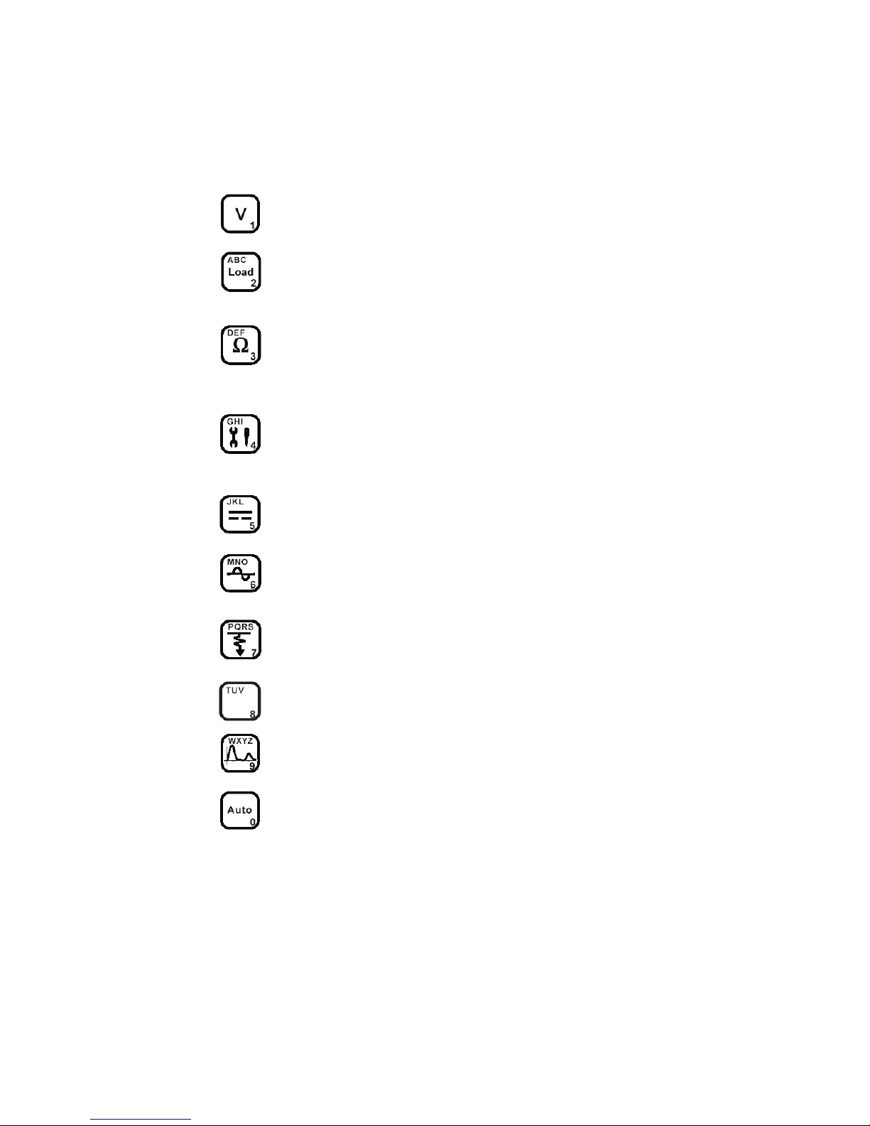
Control Keys ....................................................... 7
Function Keys ..................................................... 8
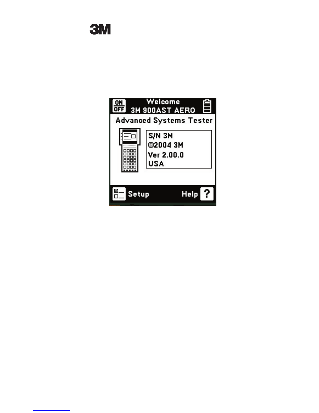
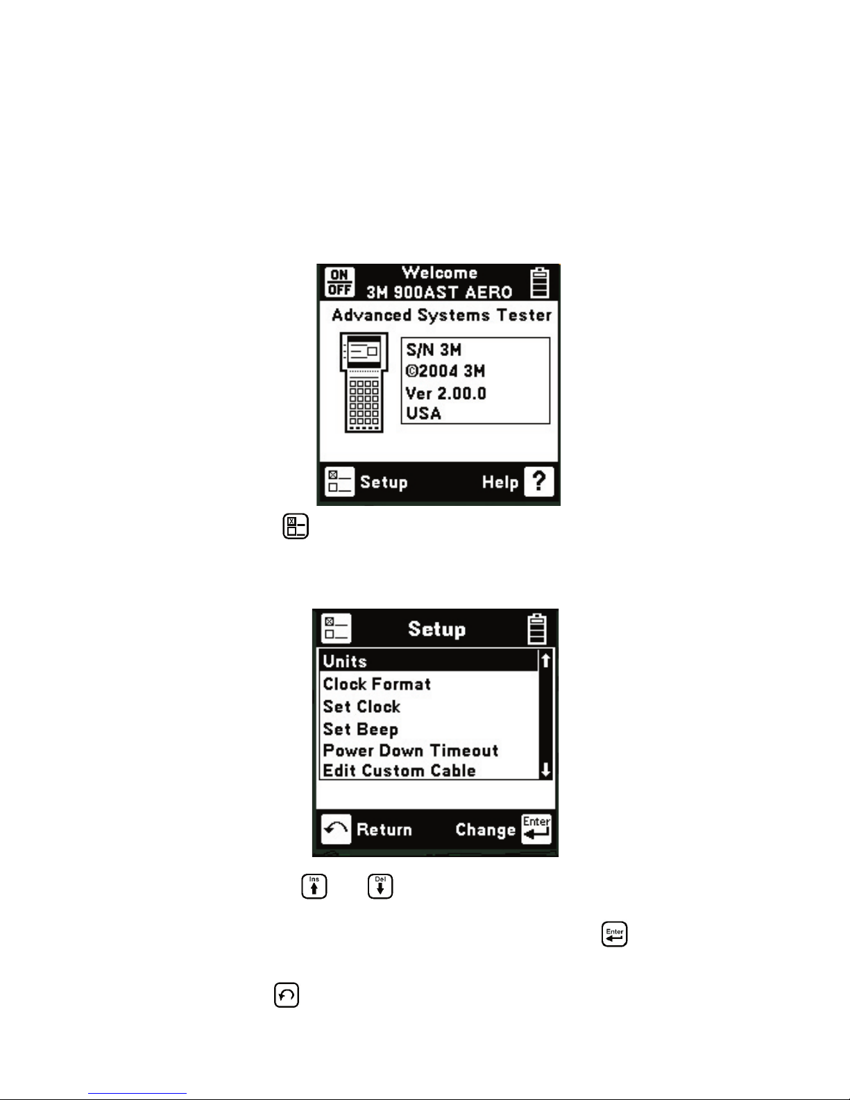
Welcome Screen ....................................................... 9
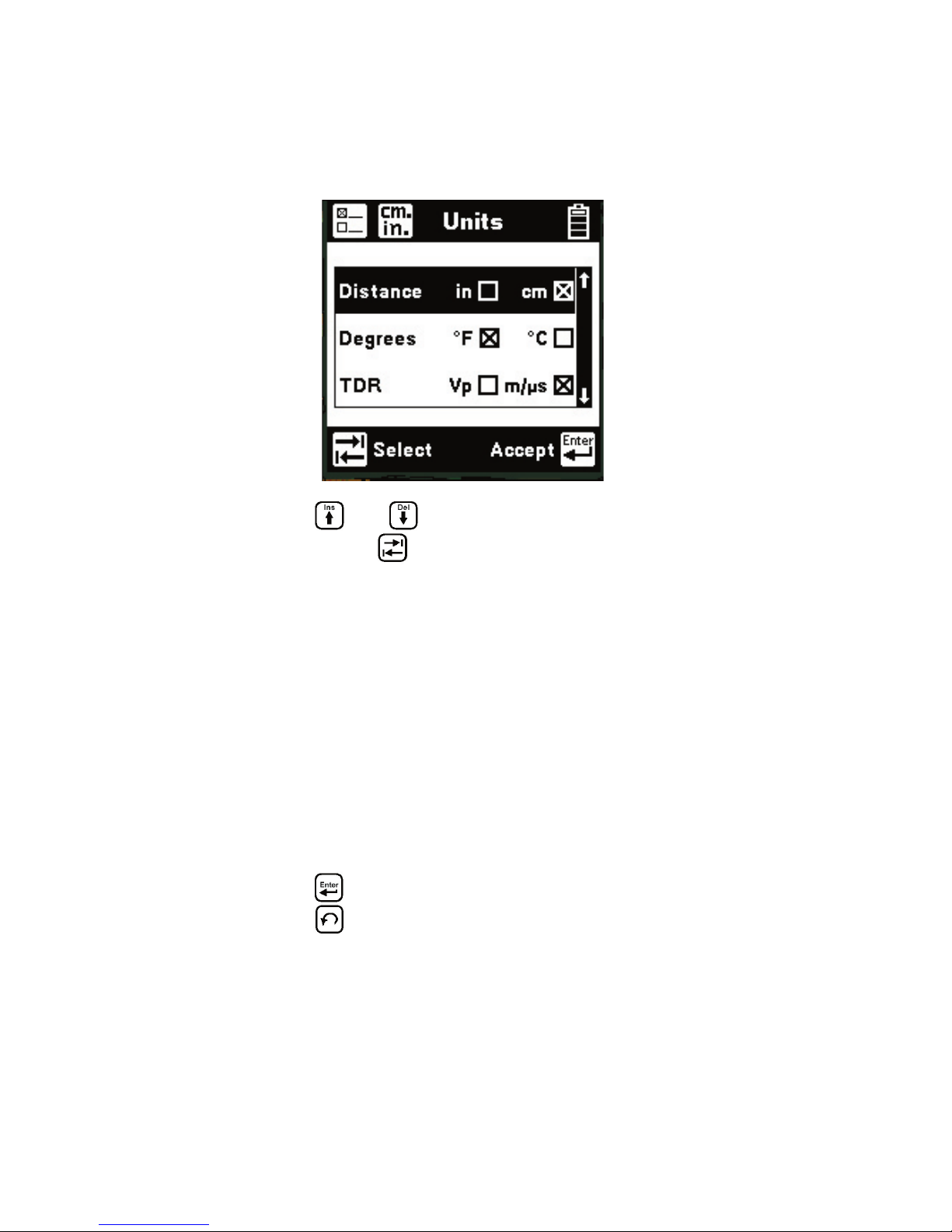
System Setup (Units, Clock Format, Set Clock, Set
Beep, Power Down Timeout, Edit Custom Cable) .. 9
Controls
Contrast/Backlight ............................................ 15
Help ................................................................... 15
High Voltage ................................................. 16
Functions
Voltage .............................................................. 17
Load Test ........................................................... 18
Resistance ......................................................... 19
Soak Test ....................................................... 20
Contact Resistance ....................................... 21
Toolbox ............................................................. 22
Self Calibration ............................................. 23
Stored Results ............................................... 24
Special Resistance ........................................ 27
Ohms/Distance ............................................. 28
Capacitance ....................................................... 29
Tone ................................................................... 30
Resistance Fault Locate (RFL) ......................... 32
TDR .................................................................. 37
Auto TDR ......................................................... 51
Care and Maintenance ............................................ 56
Specifications ......................................................... 59
Warranty Information ............................................. 60

3M™ Advanced Systems Tester 900AST Series
4
Out of the Box
What you will find when you unpack the shipping box:
• 3M™ Advanced Systems Tester 900AST Series
• Carrying case
• Battery holder and batteries
• Multimeter test leads (red/black pair, blue/yellow
pair, green)
• TDR test leads (two each, coaxial with adapters-not
assembled)
• Instruction manual
• Warranty card
The 900AST tester comes in a sturdy nylon carrying
case and should be used in the case to provide extra
protection from shock and the environment.
The battery holder holds six “AA” standard alkaline
batteries and should be installed prior to using the
unit. Please see the Care and Maintenance section
for battery installation instructions. Always initiate
a self-calibration (see Toolbox – Self Calibrate for
instructions) after installing new batteries.
The 900AST tester comes with two types of test
leads – five single-conductor test leads (red, black,
green, yellow, and blue) for most DMM (digital multi
meter) functions and two special coaxial test leads for
precision TDR measurements.
For operational information, refer to this manual or
the 900AST tester “Help” screens. For Technical
Service, Warranty or Repair questions call 800 426
8688 (US and Canada) or contact your local 3M
Representative.

3M™ Advanced Systems Tester 900AST Series
5
Front Panel
Screen
The 900AST tester screen is a high resolution
graphical LCD (Liquid Crystal Display) for viewing
text and graphics. The screen format is similar to the
following for most functions.
Test Leads
The test lead icons are shown on each of the
measurement screens. Each lead points to a color
dot on the front label that corresponds to the
actual test lead and test jack to be used. For TDR
applications using the special coaxial TDR test
lead(s), the test lead icons indicate which test jacks
(also denoted by colors) to use.

3M™ Advanced Systems Tester 900AST Series
6
Keypad
The 900AST tester keypad has twelve yellow and
red “Control Keys” and nine blue “Function Keys”.
Additional blue keys on the keypad are reserved for
future expansion and have no designation or current
function.

3M™ Advanced Systems Tester 900AST Series
7
Control Keys
Use the red and yellow keys to control the setup and
control of the 900AST tester and its functions. The
active control keys for each function are shown at the
bottom of the corresponding 900AST screen.
Use the [Return] key to return to a
previous step in a function.
Use the [Contrast] key to adjust the
contrast or to turn the backlight on or off.
Use the [Save] key for storing TDR traces.
Use the [On/Off] key to turn the 900AST
power on or off (also see “Power Down
Timeout”).
Use the [Tab] key to select between
different options.
Use the [Setup] key to change the setup of
a function.
Use the [Help] key to get context sensitive
help with any screen or function.
Use the [Enter] key to accept changes or
move to the next step in a function.
Use the
[Up]
and
[Down]
keys to
scroll to different menu options or
insert/delete characters when
editing.
Use the [Left] and [Right] keys to
move between different options or
move the TDR cursor.
Use to insert a space to the left of the cursor.
Use to delete the character above the cursor.
Use to add a ‘dash’ in a record name or a minus
sign when entering sub-zero temperature.
Edit
Use the following keys when creating record ID’s for
stored TDR traces:

3M™ Advanced Systems Tester 900AST Series
8
Function Keys
Use the blue keys to select the different tests in the
900AST tester. The blue keys become number or
letter keys when editing.
Use the [Voltage] key to measure DC or
AC voltage.
Use the [Load] key to measure the current
through a simulated load lamp.
Use the [Resistance] key to measure resistance
and access the ‘Soak Test’ and ‘Contact
Resistance’ functions.
Use the [Toolbox] key to access: Self
Calibration, Stored Results, Special
Resistance, and the Ohms to Distance
Calculator.
Use the [Capacitance] key to measure the
capacitance of a component or circuit.
Use the [Tone] key to send interrupted tone
for circuit identification.
Use the [RFL] key to find the distance to
a resistance fault between two conductors
or a conductor and ground.
This key is used for editing only.
Use the [TDR] key to activate the Time
Domain Reflectometer.
Use the [Auto] key to activate automatic TDR
trace analysis.

3M™ Advanced Systems Tester 900AST Series
9
Welcome Screen
This is the screen that you see when you first turn
on the 900AST tester. It shows the model name and
series, unit serial number, software version, and the
selected country. The battery symbol in the upper
right-hand corner of the display gives an indication
of the approximate battery capacity. Each bar
represents one-quarter of the full capacity.
Press to go to the general Setup screen from the
Welcome screen.
System Setup
Use the and keys to highlight a menu item:
units, clock format, set clock, set beep, power down
timeout, or edit/create custom cables. Press the
key to select the highlighted item.
Use to return to Welcome Screen without
making changes.

3M™ Advanced Systems Tester 900AST Series
10
Units
Use the Units setup to change the units of
measurement for the 900AST tester.
Use the and keys to highlight the desired
option. Use the key to select the parameter for
each unit of measurement.
Distance: Inches or Centimeters. This affects all
distances displayed in the 900AST tester.
Degrees: Fahrenheit or Centigrade. This affects all
temperatures used or displayed in the tester.
TDR: Vp (Velocity of Propagation) or m/µs (Meters
per Microsecond). This affects the conductor
velocity factor used by the TDR function. Vp is
normally represented as a fraction of the speed of
light and has a value less than one.
Use the key to accept any changes and return.
Use the key to return to the Welcome Screen
without making changes.

3M™ Advanced Systems Tester 900AST Series
11
Clock Format
Use the Clock Format setup to change the format of
the clock. The clock is used for the time and date
stamps in stored results.
Use the and keys to highlight either the
date or time. Use the key to select the format
parameter:
Date: m/d/y (month/day/year) or d.m.y (day.month.
year) The m/d/y format is used in the US and
Canada. The d.m.y format is used in most other
countries.
Time: 12 hours or 24 hours: This affects the number
of hours displayed in the clock. The 12 hour clock
(with a.m. and p.m.) is used in the US and Canada.
The 24 hour clock format is used in military
services and most other countries.
Use to accept the changes and return. Use
to return to the Welcome Screen without making
changes.

3M™ Advanced Systems Tester 900AST Series
12
Set Clock
Use the Set Clock setup to change the date and
time.
Use the key to select date, time, or a.m./p.m.
Use the and keys to select the digit to
change. Use the Blue keys to enter the values. Use
the and keys to select a.m. or p.m. Use
to accept the changes and return. Press to return
to the Welcome Screen without making changes.
Set Beep
Use the Set Beep setup to turn the key beeps on or off.
Use the key to toggle between on or off. Use the
key to return.

3M™ Advanced Systems Tester 900AST Series
13
Power Down Timeout
To change the power down timeout, press the
key from the startup screen, then select Power Down
Timeout. Use the and arrow keys to select
the desired timeout period, then press the key
to set that period as the default. After a period of
inactivity equal to the default period, the unit will
beep, then automatically power down to preserve
battery life.
Edit Custom Cable
This function allows you to create custom cable
types for specific applications.
Select one of the six available customizable cables
(Custom 1 through Custom 6) to edit. Use the
key to move between temperature, resistance, velocity
factor, and the label field. Use the and

3M™ Advanced Systems Tester 900AST Series
14
keys to select a digit or character to change. Use
the Blue keys to enter values or characters. Use
the and keys to insert and delete values
and characters. Use to accept any changes and
return. Use to return to the Setup menu without
making changes.
Completing the Label field is optional. This is used
for reference (i.e. “tail harness”) and can contain
up to fourteen characters and digits. The label only
appears on this screen. To use one of the custom
cables in an application (RFL, TDR), select the
desired cable (Custom 1 through Custom 6) in the
wire gauge menu of the application.
Note: Velocity of Propagation (Vp) is the rate at
which electrical signals travel through a conductor.
Vp is expressed as a fraction of the speed of light,
so it is always less than 1. Meters per microsecond
(m/µs) is an alternate way to specify cable velocity
factor. Consult your aircraft wire specifications to
obtain the correct velocity factor for the conductors
that you wish to test.

3M™ Advanced Systems Tester 900AST Series
15
Controls
Contrast/Backlight
Press the key to display the contrast screen. Use
the and keys to adjust the contrast. Press
the key again to turn the backlight on or off.
Please note that use of the backlight decreases
available battery capacity. Use the key to
return.
Help
Press the key at any time on any screen to get
context sensitive help with the present function.
Press the key to return to the previous screen.

3M™ Advanced Systems Tester 900AST Series
16
High Voltage
This screen indicates that a high voltage (120 VAC/
VDC or greater) has been detected between the test
leads when the 900 AST tester is not in the Voltage
Mode. The 900AST tester has opened an internal
relay to protect itself from damage. Use standard
customer safety practices for disconnecting the test
leads since a high voltage is present.
Press the key to restart the 900AST tester.

3M™ Advanced Systems Tester 900AST Series
17
Functions
Voltage
This function measures and displays the DC or AC
voltage between the Red and Black test leads. The
readings are ‘live’ and will vary with the voltage
being measured.
The 900AST tester initially measures DC voltage.
Press the key to switch from DC to AC voltage
measurement.
Press the key again to switch back from the AC
to the DC voltage measurement.

3M™ Advanced Systems Tester 900AST Series
18
Load Test
This function measures the DC current flowing
through a simulated load lamp inside the 900AST
tester. Connect the Red lead to the conductor under
test and the Black lead to a return or ground. The
900AST tester will continuously display the current
passing through the load as well as a bar graph
representing the approximate level of load lamp
illumination.
If the current in the load is greater than 110 mA, the
following ‘Current Warning’ screen is displayed.
This screen indicates that a high current has been
detected between the test leads and that the 900AST
tester has opened an internal relay to protect itself
from damage. Use standard safety practices for
disconnecting the test leads. Press the key to
restart the 900AST tester. Fix problems before
restarting the ‘Load’ measurement.

3M™ Advanced Systems Tester 900AST Series
19
Resistance
This function measures the resistance between the
Red and Black test leads. It is also the entry point
for accessing the Soak Test and Contact Resistance
measurements.
The “V” in the upper right corner of the screen
indicates that the resistance measurement is
compensating for any foreign voltage on the line.
Press the key to remove the voltage
compensation. Use this mode only if you have
first determined there is no DC voltage on the
conductor (by using the Voltage function). The non-
compensated measurement is slightly faster, but it is
not as accurate if there is voltage on the conductor.
The resistance measurement can be affected by
moisture on the test lead contacts or their access
points. For the most accurate measurement make
sure that these areas are dry.

3M™ Advanced Systems Tester 900AST Series
20
Soak Test
Use the Soak Test function to continuously measure
the non-compensated insulation resistance of a
conductor to another conductor, shield, or ground.
This is useful in detecting time varying faults such
as corrosive bridges.
Press the key to access the Soak test from the
Resistance screen. Connect the Red lead to the
conductor under test and the Black lead to the fault
reference (usually ground). Use the key to save
the active resistance to the “Snap Shot” area. This
measurement will not be accurate if there is foreign
voltage on the conductor.
Use the key to return to the Resistance
measurement.
Table of contents
Other 3M Test Equipment manuals

3M
3M 701 User manual

3M
3M 701-L User manual

3M
3M SE-400 Series User guide

3M
3M Charge Analyzer 711 User manual

3M
3M 746 User manual

3M
3M Wireless Tire Pressure Monitoring System User manual

3M
3M Petrifilm Instruction sheet

3M
3M Attest Super Rapid Readout Biological Indicator... User manual

3M
3M Clean-Trace UXL100 Instruction sheet

3M
3M AcoustiCal AC-300 User manual