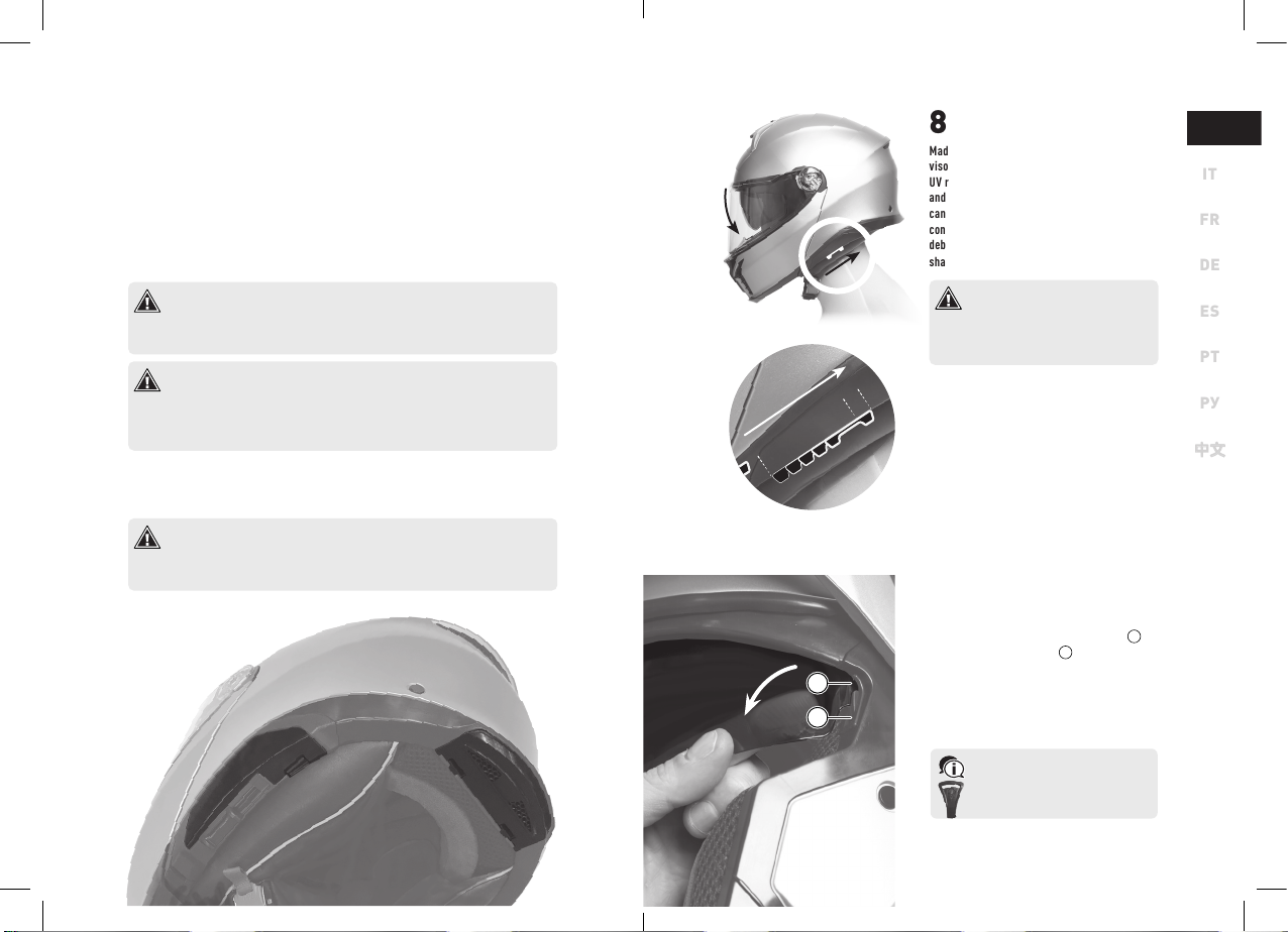
AGV Tourmodular User manual

USER MANUAL
Tourmodular

AGV is a brand owned by Dainese S.p.A.,
company with Quality Management System certified
in accordance with the standard ISO 9001.
The Pinlock®word mark and the relative logos
are a property of the Pinlock®Group B.V.
Other trademarks and trade names
are a property of their respective owners.
© 2020 Dainese S.p.A.
Reproduction forbidden. All rights reserved.

V
EN
FR
DE
ES
PT
РУ
中文中文
USER MANUAL
Specific safety instructions and requirements
for the Tourmodular helmet
IT

4 5
IT
FR
DE
ES
PT
РУ
中文中文
EN
1 USE OF THE MANUAL
Before using the helmet, you must carefully read the documentation and any integrations
thereof that comes with the product. The documentation is an integral part of the product and
must be kept throughout the lifespan of the helmet.
The AGV User Manual consists of two volumes, one general volume extended to the whole of the
range helmets and one for the specific helmet model.
Dainese S.p.A. reserves the right to make changes to the product and to the respective docu-
mentation without notice. To make sure that you have the documentation in the most recent
update available, contact an AGV Service Centre.
The products shown in the images are considered to be indicative and may differ from the
product purchased.
1.1 WORDINGS AND SYMBOLS
Prerequisite Preliminary and/or preparatory requirement to a procedure of removal,
installation, handling or cleaning of the components.
•Single action in a sequence of actions.
›Conclusion and/or the result of an operation.
Prescription and/or precautionary measure to be taken carefully. Failure to comply
may result in damage to the product, the possible impairment of the warranty and/or a
decrease in the performance of safety.
Information and/or tip for a more effective actuation, handling, control, adjustment,
maintenance and cleaning.
2 HELMET EQUIPMENT
2.1 STANDARD, INCLUDED ACCESSORIES
The following accessories are included. Make sure they are present immediately after purchase.
If any of these are missing, please contact an AGV Service Centre.
Pinlock®120 anti-fog lens Helmets collection User Manual
Bottle of silicone oil Tourmodular User Manual
tool AGV helmet fabric bag
Wind protection AGV sticker
2.2 AFTERMARKET ACCESSORIES
For more information about the available accessories for Tourmodular, go to the store at
www.agv.com or contact an AGV Service Centre.
Tourmodular can only be fitted with original AGV accessories. Please contact an
AGV Service Centre if you have any questions or concerns regarding compatibility
or assembly.
2.3 AGV INSYDE (ACCESSORY NOT INCLUDED)
Tourmodular is properly designed to accommodate its own intercom device, properly integrated inside
the shell. For more information, go to the store at www.agv.com or contact an AGV Service Centre.
Tourmodular can only be fitted with its own specific AGV intercommunication sys-
tem. Other intercom systems cannot be installed.
left
side
right
side

6 7
IT
FR
DE
ES
PT
РУ
中文中文
EN
3 COMPONENTS
1. Visor opening button
2. Chin guard central air intake vent
3. Chin guard lateral air intake vents
4. Chin guard opening button
5. Nose guard
6. Sun visor
7. Eccentric pawl for fastening
and tensioning the Pinlock®lens
8. Visor mechanism
9. Spring-loaded visor release slider
10. Upper air intake
11. Upper exhaust vents
12. Intercom housing cover(1)
with integrated lower exhaust vents
13. Micrometric fastening system
14. Intercom button panel(1) cover
15. Sun visor operation slider
16. Crown pad
17. Crown pad attachment plastic clips
18. Crown pad attachment snap button
19. Cheek pad
20. Cheek pad attachment snap button
21. Cheek pad attachment sliding guide
8
8
1
1
3
3
5
5
9
9
10
10
6
6
7
7
4
4
11
11
14
14
13
13
12
12
15
15
17
17
16
16
18
18
19
19
20
20
21
21
20
20
20
20
20
20
2
2
РУ
中文中文
(1) Accessory not included. Please see 2.3

9
IT
FR
DE
ES
PT
РУ
中文中文
EN
4 CHIN GUARD
4.1 OPENING AND CLOSING
› To open the chin guard, pull down the front
lever 1and push up the whole component.
› To close the chin guard, push it down until a
clench noise is heard.
4.2 WORKING POSITIONS
Tourmodular can be used with the chin guard
raised while riding. To do this, the chin guard
must be locked in the vertical position through
the special lever placed near the right-side
visor mechanism.
› To lock the chin guard, move the lever
from
position 1 - unlocked to position
2 - locked.
› To unlock the chin guard, move the lever
back
from position
2 - locked
to position
1 - unlocked.
To lower down the chin guard after it has
been locked, the lever must be returned
to the unlocked position.
To maximize safety while riding, the hel-
met should be used with the chin guard
closed.
5 VISOR
Optical Class 1 polycarbonate
with anti-scratch treatment on both sides
Double-engagement central button-type
locking mechanism with micro-opening
position and closure adjustment
Contoured inner surface to accommodate the
Pinlock
Pinlock
®
®
120 anti-fog lens
120 anti-fog lens
5.1 OPENING AND CLOSING
Prerequisite: the visor is closed.
› To open the visor, press its opening button 1
and, in a single movement, push upwards the
edge of the visor 2
.
Prerequisite: the visor is open.
› To close the visor, push it down until you feel
the plastic tab 3engage inside the button.
5.2 OPERATING POSITIONS
• Open position
• Micro-opening position (see 5.5)
• Closed position
While riding, the visor must be kept in the
closed or micro-opening position. It is not
safe to ride with the visor open.
If the helmet is not used for a long time,
the visor should be placed in the mi-
cro-opening position.
1 - unlocked
1 - unlocked
2 - locked
2 - locked
1
1
2
3

10 11
IT
FR
DE
ES
PT
РУ
中文中文
EN
5.6 CLOSURE ADJUSTMENT
It is possible to adjust the position of the hook-
ing cog, thus changing the pressure thereby
required to the button to open the visor.
Prerequisite: the visor is installed and open, and the
helmet is resting on a flat surface. Use a Torx®T7
screwdriver.
• Loosen the screw 1.
• Adjust the position of the engagement catch
2as desired.
The farther back the catch is posi-
tioned, the more pressure is required
on the button to open the visor.
• Tighten the screw.
› Make sure that the visor closes securely.
5.5 MICRO-OPENING
In this position the visor is firmly closed pro-
viding maximum safety, but it creates a gap
of about 5mm to allow a moderate flow of air
inside the helmet.
Prerequisite: the visor is open.
› Lower the visor until the engagement catch
1engages the opening button 2to the
first click.
If necessary, facilitate this en-
gagement by pressing the visor
open button 2lightly.
Prerequisite: the visor is closed.
› Press the opening button 2and, in a single
movement, move the visor slightly upwards
until the engagement catch 1locks the
visor to the first click.
5.3 REMOVAL
Prerequisite: the visor is fully open. Start the operation
on the right-side visor mechanism.
• Pull down the spring slider 1with a fin-
gernail, then detach the visor from the
mechanism.
› Repeat the operation on the visor mechanism
on the left-side visor mechanism.
5.4 INSTALLATION
Prerequisite: begin the operation on the right-side visor
mechanism.
• Grasp the visor and pull down the spring slid-
er 1with a fingernail.
• Place the visor on the associated mecha-
nism, so that the two engagement tabs 2
are seated into their slots 3.
• Release the spring slider.
• Repeat the above operations on the left-side
visor mechanism.
› Visor installed. Rotate it, making sure it
is securely attached and the movement is
smooth.
2
1
3
1
1
2
1
2
Opening / closing the chinguard without the vi-
sor fitted can cause the come out of the mecha-
nism 3from its sliding seat.

12 13
IT
FR
DE
ES
PT
РУ
中文中文
EN
8 SUN VISOR
Made of scratch-resistant polycarbonate, the sun
visor improvescomfortand offersprotectionfrom
UV radiation. Transmittance varies between 20%
and 35% depending on approvals. The sun visor
can be used with the chin guard raised. In this
configuration it protects the eyes from dust and
debris. The position can be adjusted based on the
shape of the nose.
The sun visor must only be used during the
day in optimal visibility conditions. It must
never be used at night, at dawn, at sunset, or
when weather conditions do not allow per-
fect visibility.
8.1 OPERATION
AND ADJUSTMENT
› To lower the sun visor, push the operating slider
towards the back of the helmet.
› Once lowered, the sun visor can be adjusted by
regulating the last 5 mm of travel.
8.2 REMOVAL
AND INSTALLATION
Prerequisite: in a seated position, rest the helmet on your
knees. Raise the chin guard and lower the sun visor.
• Grasp the sun visor and push it towards the
inside of the shell until the plastic tab 1de-
taches from its housing 2.
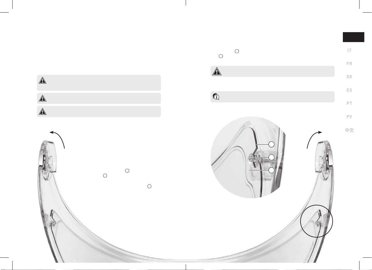
› Repeat the operations above on the other side
mechanism.
› To install the sun visor, repeat the previous op-
erations in reverse order, taking care to ensure
correct movement.
lower adjust
lower adjust
1
2
6 LUBRICATING OIL
Applying silicone oil to the visor mechanism prevents the onset of corrosion and both-
ersome creaking.
Prerequisite: the helmet is placed on one of its two sides.
• Remove the visor (see 5.3).
• Apply a moderate amount of oil to the visor mechanism of the helmet.
• Wipe off any excess oil with a cloth.
• Replicate the operations on the visor mechanism on the other side of the helmet.
› Install the visor (see 5.4).
In case of contact with skin, wash thoroughly with plenty of soap and water. In case of contact
with eyes, wash with plenty of water and seek medical advice. If swallowed, seek medical
advice. In case of inhalation, breathe in fresh, open air. Avoid exposure to sunlight. Store in a
dry place at a temperature below 50°C. Keep out of the reach of children and animals.
Do not allow the product to penetrate into the soil/subsoil. Do not allow product to
reach surface water and/or sewage systems. Keep contaminated washing water con-
tained and dispose of it appropriately. In case of penetration into watercourses, soil or
sewage systems, inform the relevant authorities. Suitable material for collection: ab-
sorbent material, organic material, sand. Do not litter the container in the environment.
7 AGV INSYDE COVERS
Do not remove the covers of AGV Insyde if you have not purchased AGV Insyde yet and
if you are not just about to assemble it. To remove the AGV Insyde covers refer to the
AGV Insyde assembly booklet, provided with the accessory. Removing the covers im-
properly and without having the instructions can damage the product.
.If there are difficulties to remove the
sun visor, please, use the tool provided
with the helmet. Insert the tool betwe-
en the sun visor and the slot

14 15
IT
FR
DE
ES
PT
РУ
中文中文
EN
9 PINLOCK®120
ANTI-FOG LENS
A hydrophilic plastic device with anti-fog features capable of absorbing humidity.
By fitting precisely into the specially shaped seat on the inner surface of the visor,
it creates an air pocket that limits the onset of fogging without compromising the
field of view.
Anti-fog devices delay the formation of condensation, but do not guarantee that the
problem will not occur. Such devices delay the onset of the problem. Therefore, under
extreme environmental conditions, fogging of the visor may occur.
It is strongly recommended the use of Pinlock®lens with air temperatures below 20°C
and/or humidity levels above 70% and/or in the rain.
The Pinlock®lens should be handled with care and without the use of tools that could
scratch it or abrade its surface.
9.2 REMOVAL
Prerequisite: remove the visor from the helmet (see 5.3).
• Stretch the visor slightly by grasping it at the ends.
• Lift the lens 1by acting on its lower central part, then release it from the eccentric pawls
2on the visor; first on one side, then on the other.
› The lens is now detached. Remove it.
The Pinlock®lens should be handled with care and without the use of tools that could
scratch it or abrade its surface.
9.3 TENSIONING
See the illustrative document included in the Pinlock®lens packaging.
1
2
3
9.1 INSTALLATION
Prerequisite: the visor is removed from the helmet (see
5.3) and has been thoroughly cleaned. The lens is rest-
ing on the inner surface of the visor, facing so that the
silicone gasket is in contact with the visor.
• Stretch the visor slightly by grasping it at
the ends.
• Attach the lens 1to the eccentric pawls
2of the visor; first on one side, then on
the other.
• Ensure that the silicone gasket 3of the
lens adheres perfectly to the visor along its
entire length.
› Remove the protective film from the lens and
install the visor on the helmet (see 5.4).

16 17
IT
FR
DE
ES
PT
РУ
中文中文
EN
10.2 INSTALLATION
Prerequisite: in a seated position, place the helmet upside-down on your knees. Release the fastening
system. Lift the chin guard and sun visor. Begin the operation on the right side cheek pad.
• Attach the cheek pad to the helmet by inserting the plastic strip 7though its guide
underneath the base trim.
The guide fixing the cheek pad plastic strip guide is interrupted by a screw 8.
Be sure to continue inserting the plastic strip beyond this interruption.
• Place the plastic ring 5so that it encircles the snap button 6located on the front-bot-
tom part of the shell.
• Insert the fastening system 3through the special opening 4in the cheek pad.
• Bend cheek pad and lay it to the polystyrene shell, attaching the four snap buttons 1.
›
›
Repeat the previous operations on the left side.
1
3
2
65
4
1
1 6
5
11
10 CHEEK PADS
10 CHEEK PADS
10.1 REMOVAL
10.1 REMOVAL
Prerequisite: in a seated position, place the helmet up-
side-down on your knees. Release the fastening system.
Lift the chin guard and sun visor. Begin the operation on
the right side cheek pad.
•
•
Insert your hand inside the helmet between
the cheek pad and the polystyrene shell, then
unhook the four snap buttons
unhook the four snap buttons 1
, releasing
, releasing
the cheek pad from the polystyrene shell.
•
•
Bend
Bend
the cheek pad
the cheek pad 2
towards the inside of
the helmet, then remove the fastening sys-
tem
tem 3
through its appropriate gap
through its appropriate gap 4
(don't
(don't
release the retention system snap button).
•
•
Free the plastic ring
Free the plastic ring 5
from the snap button
6
located on the lower corner of the shell.
•
•
Pull out the whole cheek pad by slipping the
plastic band
plastic band 7
from its guide.
from its guide.
›
›
Repeat the previous operations on the left
side cheek pad.
side cheek pad.
8
7

18 19
IT
FR
DE
ES
PT
РУ
中文中文
EN
1A
1A
12 WIND PROTECTION
12.1 INSTALLATION AND REMOVAL
Prerequisite: in a seated position, rest the helmet on your knees with the chin guard lowered.
› To install the wind guard, lift the base trim of the chin guard with your fingers and align
the two holes
1
drilled in the plastic strip with the two hooks
2
below the base trim.
› To remove the wind guard, lift the bottom edge of the chin guard with your fingers and pull
the wind guard towards the inside of the helmet, so that the two holes 1drilled in the
plastic strip are released from the two hooks 2located below the bottom edge
13 NOSE GUARD
13 NOSE GUARD
13.1 INSTALLATION AND REMOVAL
Prerequisite: in a seated position, rest the helmet on your knees. Chin guard closed, visor raised.
›
›
Place the nose guard in position, first inserting the central clip
1
, then the two side ones
2
.
.
›
›
To remove the nose guard, first detach the side clips
2
individually, then the middle clip
1
.
.
11 CROWN PAD
11.1 REMOVAL
Prerequisite: in a seated position, place the helmet upside-down on your knees. Lift the chin guard and lock it.
• Release the two snap buttons 1A by detaching them from the neck area 1B.
• Release the two cheek pads upper snap buttons 2A, to release the fabric headset ring 2B.
› Release the five front plastic clips of the headset 3A from their seats 3B located in the
front area of the polystyrene shell.
11.2 INSTALLATION
11.2 INSTALLATION
Prerequisite: in a seated position, place the helmet upside-down on your knees. Lift the chin guard and lock it.
•
•
Place the crown pad inside the helmet with the snap buttons positioned at the back.
•
•
Snap the two rear snap buttons
1A
1A
located in the neck area
1B
1B
.
.
•
•
Attach the two upper snap buttons of the pad
2A
2A
, interposing the crown pad fabric rings
2B
2B
.
.
›
›
Attach the five front plastic clips of the headset
3A
3A
to their seats
to their seats
3B
3B
.
.
3A
3A
3A
3A
3A
3A
3A
3A
3A
3A
1A
1A
1B
1B
1B
1B
2B
2B
2A
2A
2B
2B
3B
3B
3B
3B
3B
3B
3B
3B
3B
3B
1
1
2
2
1 22

20
V
14 VENTILATION
14 VENTILATION
Ventilation of the interior is achieved with
three air intake vents located on the chin guard
and one on the top of the shell. The polystyrene
inner shell is specifically designed to channel
the air flow through the rear exhaust vents.
14.1 UPPER
14.1 UPPER
AIR INTAKE VENTS
AIR INTAKE VENTS
›
›
To open the air intake vent, move the slider
1
towards the back of the helmet.
›
›
To close the air intake vent, move the slider
1
towards the front of the helmet.
14.2 CHIN GUARD
14.2 CHIN GUARD
AIR INTAKE VENTS
AIR INTAKE VENTS
Prerequisite:
Prerequisite: in a seated position, rest the helmet on
your knees. Raise the chin guard
.
.
›
›
To open the central air intake vent, press
its
its
lower portion
lower portion 2
towards the inside of the
chin guard.
chin guard.
›
›
To open the side air intake vents
To open the side air intake vents 3
, move
, move
the sliders towards the outside of the shell.
open
open
close
close
1
open
open
closed
closed
open
open
closed
closed
3 3
2
21
IT
FR
DE
ES
PT
РУ
中文中文
MANUALE DI UTILIZZO
EN
Istruzioni e prescrizioni di sicurezza specifiche
per il casco Tourmodular

22 23
EN
FR
DE
ES
PT
РУ
中文中文
IT
1 USO DEL MANUALE
Prima di utilizzare il casco è necessario leggere attentamente la documentazione e le sue even-
tuali integrazioni a corredo del prodotto. La documentazione è parte integrante del prodotto e
deve essere conservata durante tutto il ciclo vitale del manufatto.
Il Manuale di utilizzo dei caschi AGV è costituito da due volumi, uno generale esteso a tutta la
gamma e uno per ciascun specifico modello di casco.
Dainese S.p.A. si riserva di apportare modifiche al prodotto e alla sua rispettiva documentazione
senza notifica alcuna. Per accertarsi di disporre della documentazione nel più recente aggiorna-
mento disponibile, contattare un AGV Service Center.
I prodotti riportati nelle immagini sono da considerarsi indicativi e potrebbero differire dal
prodotto acquistato.
1.1 DICITURE E SIMBOLI
Prerequisito Requisito preliminare e/o propedeutico a un'operazione di rimozione, installazio-
ne, movimentazione o pulizia dei componenti.
•Singola azione in una sequenza di azioni.
›Conclusione e/o risultato di un’operazione.
Prescrizione e/o misura precauzionale da adottare scrupolosamente. La mancata os-
servanza può comportare un danneggiamento del prodotto, un eventuale decadimento
della garanzia e/o un calo delle prestazioni di sicurezza.
Informazione e/o avvertenza per una più efficace esecuzione delle procedure di azio-
namento, movimentazione, controllo, regolazione, manutenzione e pulizia
.
2 DOTAZIONE DEL CASCO
2.1 ACCESSORI DI SERIE
Gli accessori riportati di seguito sono inclusi. Accertarsi della loro presenza subito dopo l'acqui-
sto. Qualora qualcuno di questi mancasse, contattare un AGV Service Center.
Lente anti appannamento Pinlock®120 Helmets collection User Manual
Boccetta di olio al silicone Tourmodular User Manual
Attrezzo Sacca porta-casco AGV in tessuto
Antivento Adesivo con logo AGV
2.2 ACCESSORI AFTER MARKET
Per maggiori informazioni sugli accessori disponibili per Tourmodular collegarsi allo store nel
sito www.agv.com o contattare un AGV Service Center.
Tourmodular può essere equipaggiato esclusivamente con accessori originali AGV. Si
prega di contattare un AGV Service Center per qualsiasi dubbio o richiesta a proposito
di compatibilità o assemblaggio.
2.3 AGV INSYDE PER Tourmodular
(accessorio non incluso)
Tourmodular è progettato per accogliere il proprio specifico sistema di intercomunicazione,
appositamente integrato nella calotta. Per maggiori informazioni collegarsi allo store nel sito
www.agv.com o contattare un AGV Service Center.
Tourmodular può essere equipaggiato esclusivamente con il proprio specifico siste-
ma di intercomunicazione AGV. Altri sistemi di intercomunicazione non possono esse-
re assemblati.
lato
sinistro
lato
destro

24 25
EN
FR
DE
ES
PT
РУ
中文中文
IT
3 COMPONENTI
1. Pulsante di apertura visiera
2. Presa d'aria centrale della mentoniera
3. Presa d'aria laterale della mentoniera
4. Pulsante di apertura mentoniera
5. Paranaso
6. Parasole
7. Bussola eccentrica per assemblaggio
e tensionamento della lente Pinlock®
8. Meccanismo visiera
9. Cursore a molla per sgancio visiera
10. Presa d'aria superiore
11. Estrattore d'aria superiore
12. Cover dell'alloggiamento dell'intercom(1)
con integrato l'estrattore d'aria posteriore
13. Sistema di ritenzione micrometrico
14. Cover dell'alloggiamento
della pulsantiera intercom(1)
15. Cursore di azionamento visiera parasole
16. Cuffia
17. Ganci plastici di attacco della cuffia
18. Bottoni a pressione
di attacco della cuffia
19. Guanciale
20. Bottoni a pressione
di attacco del guanciale
21. Guida di inserimento del guanciale
per aggancio alla calotta
8
8
1
1
3
3
5
5
9
9
10
10
6
6
7
7
4
4
11
11
14
14
13
13
12
12
15
15
17
17
16
16
18
18
19
19
20
20
21
21
20
20
20
20
20
20
2
2
РУ
中文中文
(1) Accessorio non incluso. Cfr 2.3

27
EN
FR
DE
ES
PT
РУ
中文中文
IT
4 MENTONIERA
4.1 APERTURA E CHIUSURA
› Per aprire la mentoniera, tirare verso il basso
la relativa leva 1e spingere verso l'alto
l'intero componente.
› Per chiudere la mentoniera, abbassare il
componente fino alla completa chiusura.
4.2 POSIZIONI DI LAVORO
Tourmodular può essere usato con la mentoniera
sollevata mentre si guida. Per farlo è necessario
bloccare la mentoniera in posizione verticale
tramite l'apposita leva collocata in prossimità
del meccanismo visiera del lato destro.
› Per bloccare la mentoniera, spostare la leva
dalla posizione 1 - sbloccata alla posizione
2 - bloccata.
› Per sbloccare la mentoniera spostare la leva
dalla posizione 2 - bloccata alla posizione
1 - sbloccata.
Per abbassare la mentoniera dopo che è
stata bloccata, è necessario riportare la
leva in posizione di sblocco.
Per massimizzare la sicurezza durante la
guida la mentoniera deve essere abbassa-
ta.
5 VISIERA
Policarbonato di classe ottica 1
con trattamento antigraffio su entrambi i lati.
Meccanismo di serraggio di tipo a pulsante
centrale a doppio ingaggio con posizione di
microapertura e regolazione della chiusura.
Superficie interna sagomata per accogliere la
lente antiappannamento Pinlock
®
®
.
.
5.1 APERTURA E CHIUSURA
Prerequisito: la visiera è chiusa.
› Per aprire la visiera, premere il pulsante di
apertura 1e, in un singolo gesto, spingere
verso l'alto la visiera 2.
Prerequisito: la visiera è aperta.
› Per chiudere la visiera, spingerla verso il
basso fino a che non si avverte il dente pla-
stico 3agganciarsi all'interno del pulsante
di apertura.
5.2 POSIZIONI DI LAVORO
• Posizione aperta
• Posizione di mirco-apertura (cfr. 5.5)
• Posizione chiusa
Durante la guida la visiera deve essere
mantenuta in posizione chiusa o di micro-
apertura. Non è sicuro procedere in marcia
con la visiera aperta.
Qualora il casco non venisse utilizzato per
un lungo periodo, è opportuno disporre la
visiera in posizione di micro-apertura.
1 - sbloccata
1 - sbloccata
2 - bloccata
2 - bloccata
1
1
2
3

28 29
EN
FR
DE
ES
PT
РУ
中文中文
IT
5.6 REGOLAZIONE
DELLA CHIUSURA
È possibile regolare l'avanzamento del dente di
ingaggio, modificando così l'affondamento ne-
cessario al pulsante per aprire la visiera.
Prerequisito: la visiera è installata e aperta, e il casco
poggiato una superficie piana. Operare dotandosi di un
cacciavite Torx®T7.
• Svitare la vite 1.
• Regolare a piacere l'avanzamento del dente
di ingaggio 2.
Maggiore è l'arretramento del dente,
maggiore è la pressione necessaria
sul pulsante per aprire la visiera.
• Avvitare la vite.
› Assicurarsi che la visierasichiuda saldamente.
5.5 MICRO-APERTURA
In questa posizione la visiera è saldamente
chiusa offrendo la massima sicurezza, ma rea-
lizza una fessura di circa 5mm per consentire un
moderato afflusso di aria all'interno del casco.
Prerequisito: la visiera è aperta.
› Abbassare la visiera fino a che il dente pla-
stico 1ingaggi il pulsante di apertura 2
al primo scatto.
Agevolare l'ingaggio premendo
leggermente il pulsante di apertura
visiera 2.
Prerequisito: la visiera è chiusa.
› Premere il pulsante di apertura 2e, in un
singolo gesto, spostare leggermente verso
l'alto la visiera fino a che il dente plastico 1
blocchi la visiera al primo scatto.
5.3 RIMOZIONE
Prerequisito: la visiera è completamente aperta. Iniziare
l'operazione sul meccanismo visiera del lato destro.
• Spingere verso il basso il cursore a molla 1
con un'unghia, quindi staccare la visiera dal
meccanismo.
› Ripetere l'operazione sul meccanismo visiera
del lato sinistro.
5.4 INSTALLAZIONE
Prerequisito: iniziare l'operazione sul meccanismo visie-
ra del lato destro.
• Afferrare la visiera e spingere verso il basso
il cursore a molla 1con un'unghia.
• Posizionare la visiera sul relativo meccani-
smo così che i due denti di ingaggio 2siano
collocati all'interno delle loro sedi 3.
• Rilasciare il cursore a molla.
• Ripetere le operazioni sul meccanismo visie-
ra del lato sinistro.
› Visiera installata. Ruotarla, verificando che
il montaggio sia saldo e movimento fluido.
2
1
3
1
1
2
1
2
Aprire / chiudere la mentoniera senza la visiera
montata, può portare all'uscita del meccanismo
3dalla sua sede di scorrimento.

30 31
EN
FR
DE
ES
PT
РУ
中文中文
IT
8 PARASOLE
Realizzato in policarbonato antigraffio, migliora il
comfort e offre protezione dalle radiazioni UV. La
trasmittanza varia tra 20% e 35% a seconda delle
omologazioni. Può essere usato con mentoniera
sollevata e in questa configurazione protegge
gli occhi da pulviscolo e detriti. La posizione può
essere regolata in base alla morfologia del naso.
Il parasole può essere usato esclusivamente di
giorno in condizioni di visibilità ottimali. Non
deve essere usato di notte, all'alba, al tramonto,
né quando le condizioni atmosferiche non con-
sentano una visibilità perfetta.
8.1 AZIONAMENTO
E REGOLAZIONE
› Per abbassare il parasole, spingere il cursore di
azionamento verso il retro del casco.
› Una volta abbassato, il parasole può essere
regolato aggiustando gli ultimi 5mm di corsa.
8.2 RIMOZIONE
E INSTALLAZIONE
Prerequisito: disporsi in posizione seduta poggiando il
casco sulle gambe. Sollevare la mentoniera e abbassare il
parasole.
• Afferrare il parasole e spingerlo verso l'interno
della calotta fino a che il dente plastico 1che
lo vincola si stacchi dalla sede 2
› Ripetere le operazioni operando sul lato oppo-
sto.
› Per installare il parasole, ripetere le precedenti
operazioni in ordine inverso, avendo cura in ulti-
modi verificarne il corretto movimento.
1
abbassare regolare
abbassare regolare
2
6 OLIO LUBRIFICANTE
L'applicazione dell'olio al silicone sul meccanismo visiera evita l'insorgere di corrosio-
ne e scricchiolii parassiti.
Prerequisito: il casco è poggiato su uno dei due lati.
• Rimuovere la visiera (cfr. 5.3).
• Applicare una moderata quantità di olio sul meccanismo visiera.
• Rimuovere con un panno la quantità di olio in eccesso.
• Replicare le operazioni sul meccanismo visiera dell'altro lato del casco.
› Installare la visiera (cfr. 5.4).
In caso di contatto con la pelle, lavare abbondantemente con acqua e sapone. In caso
di contatto con gli occhi, lavare abbondantemente con acqua e consultare un medico. In
caso di ingestione, consultare un medico. In caso di inalazione, respirare aria aperta.
Evitare l'esposizione ai raggi solari. Conservare in un luogo asciutto e a una tempera-
tura inferiore a 50°C. Conservare al di fuori della portata di bambini e animali.
Impedire la penetrazione del prodotto nel suolo/sottosuolo. Impedire il deflusso del
prodotto nelle acque superficiali e/o nella rete fognaria. Trattenere l'acqua di lavaggio
contaminata ed eliminarla. In caso di penetrazione in corsi d'acqua, suolo o sistema
fognario informare le autorità responsabili. Materiale idoneo alla raccolta: materiale
assorbente, organico, sabbia. Non disperdere il contenitore nell'ambiente.
7 AGV INSYDE COVERS
Non rimuovere le due coperture di AGV Insyde se non si ha ancora acquistato Insyde e
se non si sta per assemblarlo. Per rimuovere le coperture AGV Insyde, consultare il
documento illustrativo di AGV Insyde, fornito con il componente. La rimozione impropria
delle coperture e eseguita senza le istruzioni può danneggiare il prodotto.
Nel caso in cui si trovasse difficolta
nella rimozione del parasole, utiliz-
zare l'attrezzo in dotazione con il
casco. Inserire l'attrezzo tra il para-
sole a la sede.

32 33
EN
FR
DE
ES
PT
РУ
中文中文
IT
9 LENTE PINLOCK®120
ANTIAPPANNAMENTO
Dispositivo in materiale plastico idrofilo con caratteristiche antiappannamento in gra-
do di assorbire l’umidità
.
Inserendosi con precisione nell'apposita sede sagomata sulla superficie interna della
visiera, crea una sacca d'aria che limita l’insorgere dell’appannamento senza compro-
mettere il campo visivo
.
I dispositivi antiappannamento ritardano la formazione della condensa, ma non garanti-
scono che il fenomeno non insorga. Tale dispositivo ritarda la comparsa del fenomeno.
Pertanto, in condizioni ambientali estreme si può verificare l’appannamento della visiera.
Si raccomanda sempre l’utilizzo della lente di marca Pinlock®con temperatura dell’aria
inferiore a 20°C e/o con umidità superiore al 70% e/o in presenza di pioggia
.
La lente Pinlock®va maneggiata con cura e senza l’ausilio di strumenti che possano
graffiarla o abraderne la superficie.
9.2 RIMOZIONE
Prerequisito: la visiera è rimossa dal casco (cfr. 5.2).
• Tendere leggermente la visiera afferrandola alle estremità.
• Sollevare la lente 1agendo sulla sua parte centrale inferiore, quindi svincolarla dai perni
2ricavati sulla visiera; prima su un lato, poi sull'altro.
› La lente è ora staccata. Rimuoverla.
La lente Pinlock®va maneggiata con cura e senza l’ausilio di strumenti che possano
graffiarla o abraderne la superficie.
9.3 PRETENSIONAMENTO
Consultare il documento illustrativo incluso nel packaging della lente Pinlock®120
1
2
3
9.1 INSTALLAZIONE
Prerequisito: la visiera è rimossa dal casco (cfr 5.3) ed è
stata pulita a fondo. La lente è poggiata sulla superficie
interna della visiera, orientata con la guarnizione in sili-
cone a contatto con la visiera.
• Tendere leggermente la visiera afferrandola
alle estremità.
• Fissare la lente 1sui perni 2della visiera;
prima su un lato, successivamente sull’altro.
• Accertarsi che la guarnizione in silicone 3
della lente aderisca perfettamente alla vi-
siera lungo tutta la sua lunghezza.
› Rimuovere la pellicola protettiva dalla lente
e installare la visiera sul casco (cfr. 5.3).

34 35
EN
FR
DE
ES
PT
РУ
中文中文
IT
10.2 INSTALLAZIONE
Prerequisito: disporsi in posizione seduta poggiando il casco rovesciato sulle gambe. Slacciare il sistema
di ritenzione. Sollevare la mentoniera e il parasole. Iniziare l'operazione sul lato destro.
• Attaccare il guanciale al casco infilando la banda plastica 7attraverso la sua guida
collocata all'interno del bordo base.
La guida della banda plastica del guanciale è interrotta da una vite
8
. Assicurar-
si
di proseguire l'inserimento della banda plastica anche oltre questa interruzione.
• Disporre l'anello plastico 5di modo che cinga il bottone a pressione 6disposto nella
parte inferiore del casco.
• Infilare il sistema di ritenzione
3
attraverso l'apposita apertura
4
praticata nel guanciale.
• Piegare il guanciale verso la calotta in polistirolo e agganciare i quattro bottoni a pressione
1
.
›
›
Ripetere le operazioni precedenti operando sul lato sinistro.
65
1
1 6
5
11
10 GUANCIALI
10 GUANCIALI
10.1 RIMOZIONE
10.1 RIMOZIONE
Prerequisito: disporsi in posizione seduta poggiando il
casco rovesciato sulle gambe. Slacciare il sistema di
ritenzione. Sollevare la mentoniera e il parasole. Iniziare
l'operazione sul lato destro.
•
•
Infilare la mano all'interno del casco tra il
guanciale e la calotta in polistirolo, quindi
sganciare i quattro bottoni a pressione
1
che
fissano il guanciale alla calotta in polistirolo
.
.
•
•
Piegare il guanciale
2
verso l'interno del ca-
sco, quindi rimuovere il sistema di ritenzione
3
attraverso l'apposito passaggio
4
(non
(non
sganciare il suo bottone a sgancio rapido).
•
•
Liberare l'anello plastico
Liberare l'anello plastico 5
dal bottone a
dal bottone a
pressione
pressione 6
situato nell'angolo inferiore
della calotta.
della calotta.
•
•
Estrarre l'intero guanciale sfilando la banda
plastica
plastica 7
dalla sua guida disposta all'in-
terno del bordo base.
›
›
Ripetere le operazioni precedenti sul guan-
ciale del lato sinistro.
1
3
2
4
8
7

36 37
EN
FR
DE
ES
PT
РУ
中文中文
IT
1A
1A
12 ANTIVENTO
12.1 INSTALLAZIONE E RIMOZIONE
Prerequisito: disporsi in posizione seduta poggiando il casco sulle gambe con la mentoniera abbassata.
› Per installare la protezione antivento, sollevare con le dita il bordo base della mentoniera
e disporre i due fori
1
praticati sulla banda plastica in corrispondenza dei due relativi
agganci
2
ricavati al di sotto del bordo base.
› Per rimuovere la protezione antivento, sollevare con le dita il bordo base della mentoniera
e tirare l'antivento verso l'interno del casco, di modo che
i due fori
1
praticati sulla banda
plastica si svincolino dai due relativi agganci
2
ricavati al di sotto del bordo base
.
13 PARANASO
13 PARANASO
13.1 INSTALLAZIONE E RIMOZIONE
Prerequisito: disporsi in posizione seduta poggiando il casco sulle gambe
. Mentoniera chiusa, visiera sollevata.
›
›
Disporre il paranaso in posizione, inserendo prima la clip di aggancio centrale
Disporre il paranaso in posizione, inserendo prima la clip di aggancio centrale 1
, quindi
, quindi
i due laterali
i due laterali 2
.
.
›
›
Per rimuovere il paranaso, staccare prima singolarmente le clip di aggancio laterali
Per rimuovere il paranaso, staccare prima singolarmente le clip di aggancio laterali 2
,
,
quindi quella centrale
quindi quella centrale 1
.
.
11 CUFFIA
11.1 RIMOZIONE
11.1 RIMOZIONE
Prerequisito: disporsi in posizione seduta poggiando il casco rovesciato sulle gambe. Sollevare la men-
toniera e bloccarla (cfr 4.2).
•
•
Sganciare i due bottoni a pressione posteriori
1A
1A
staccandoli dall'area della nuca
1B
1B
.
.
•
•
Sganciare i due bottoni a pressione superiori dei guanciali
2A
2A
, di modo da svincolare l'a-
nello di tessuto della cuffia
2B
2B
.
.
›
›
Sganciare le cinque clip plastiche frontali della cuffia
3A
3A
dalle loro sedi
dalle loro sedi
3B
3B
poste nella
poste nella
zona frontale della calotta in polistirolo.
11.2 INSTALLAZIONE
11.2 INSTALLAZIONE
Prerequisito: disporsi in posizione seduta poggiando il casco rovesciato sulle gambe. Sollevare la men-
toniera e bloccarla (cfr 4.2).
•
•
Disporre la cuffia all'interno del casco, con i bottoni a pressione posizionati al posteriore.
•
•
Agganciare i due bottoni a pressione posteriori
1A
1A
disposti nell'area della nuca
1B
1B
.
.
•
•
Attaccare i due bottoni a pressione superiori dei guanciali
2A
2A
, interponendovi i due anelli
in tessuto della cuffia
2B
2B
.
.
›
›
Agganciare le cinque clip plastiche frontali della cuffia
3A
3A
nelle loro sedi
nelle loro sedi
3B
3B
.
.
3A
3A
3A
3A
3A
3A
3A
3A
3A
3A
1A
1A
1B
1B
1B
1B
2B
2B
2A
2A
2B
2B
3B
3B
3B
3B
3B
3B
3B
3B
3B
3B
1 22
1
1
2
2
Table of contents
Languages:
Other AGV Motorcycle Accessories manuals
Popular Motorcycle Accessories manuals by other brands

R&G
R&G FI0127BK Fitting instructions

hepco & becker
hepco & becker 503998 00 01 manual

hepco & becker
hepco & becker 6307526 00 01 instructions

SW-Motech
SW-Motech GPT.07.726.20002/B Mounting instructions

motea
motea Bagtecs XB38 instruction manual

SW-Motech
SW-Motech ALU-RACK GPT.06.627.15000/B Mounting instructions