AGV K-5 Jet User manual

DOWN
UP
K-5 Jet
Italiano 2
English 11
Français 20
Deutsch 29
Español 38
Portuguese 47

DOWN
UP
1
2
Vi consigliamo di eseguire le operazioni che seguono appoggiando il casco su una supercie piatta.
Italiano
1) VISIERA
Sede innesto superiore
Innesto superiore
Dente visiera
Fermo visiera
Innesto inferiore
Cursore fermo visiera
1.1) Rimozione/Installazione Visiera
La visiera è in policarbonato antigrafo ed è dotata di innesti che si inseriscono
nelle sedi della base movimento. Il dente della visiera interagisce con i denti
della base movimento per consentire la stabilità in apertura della visiera nelle
diverse posizioni.
Per rimuovere la visiera, sollevarla no allo scatto
intermedio di apertura (1): esso è tale che il dente di
aggancio A è allineato con la sede ricavata sul mec-
canismo stesso B (2). Partendo da uno dei due lati del
casco, tirare verso il basso il cursore del fermo visie-
ra (3) ed estrarre gli innesti di aggancio della visiera.
Ripetere l’operazione anche dall’altro lato e rimuovere
la visiera.
Per installare la visiera, partendo da un lato del casco,
allineare il dente di aggancio A alla sede sul meccani-
smo B e contemporaneamente inserire l’innesto supe-
riore della visiera nella sua sede della base movimento
(4). Successivamente, inserire l’innesto inferiore della
visiera nel fermo visiera (eventualmente aiutandosi
tirando verso il basso il cursore) (5). Ripetere l’ope-
razione anche dall’altro lato. Abbassare la visiera e
vericarne il buon funzionamento.
Inoltre controllare che la visiera in fase di chiusura -
nisca perfettamente in sede, ovvero che i magneti ed
i denti di centraggio posti sul lato inferiore della visiera
entrino perfettamente nelle loro sedi.
K-5 Jet
THIS HELMET’S SHELL IS MADE OF COMPOSITE FIBER
THIS HELMET’S LINER IS MADE OF POLYSTIRENE (EPS)
2
Perno visiera
DOWN
UP
DOWN
UP
1 2
3 4
5
DOWN
UP
DOWN
UP
A
B
DOWN
UP
A
B
N.B. Nel caso in cui la visiera non aderisca perfettamente al prolo del bordo
in gomma del casco, potrebbe essere necessaria una regolazione o sostitu-
zione della base meccanismo visiera. In questo caso rivolgersi ad un punto
di assistenza AGV.

3
2
1
DOWN
UP
2) SISTEMI DI VENTILAZIONE
2.1) Apertura/chiusura prese aria frontali
Per aprire/chiudere le prese d’aria frontali, agire sul
cursore no a quando non si sente lo scatto che
indica il blocco del cursore in posizione (1-2).
2.2) Apertura/chiusura estrattore posteriore
Per aprire/chiudere l’estrattore posteriore agire sul
cursore centrale.
Canalizzazioni nel polistirolo
Prese d’aria frontali
Estrattore d’aria superiore
Aperto
Chiuso
Cursore
Cursore
Aperto
Chiuso
Cursore
Aperto Chiuso

4
3) INTERNI
Cufa
Guanciali
3.1) Rimozione/Installazione guanciali
Per rimuovere i guanciali, impugnarli nella parte an-
teriore del casco e tirarli nella direzione della freccia
per liberarli da tutti i bottoni automatici (1). Slare la
bandella di plastica dalle sue sedi ed estrarre i guan-
ciali (2).
Per rimontare i guanciali, inlarli nel casco e inserire la
bandella di plastica nelle sue sedi sul lato della calotta
(3) e far scattare i bottoni automatici di connessione
(4).
Vericare che i guanciali siano perfettamente assicu-
rati al casco.
VVVVVV
VVVVVV
VVVVVV
VVVVVV
VVVVVV
VVVVVV
VVVVVV
VVVVVV
VVVVVV
VVVVVV
VVVVVV
1 2
34

5
1
3
2
4
3.2) Rimozione/installazione ear cushion
Nel sacchetto istruzioni viene fornita una coppia di ear
cushion da installare sui guanciali (1).
L’ear cushion viene montato sul guanciale facendo
coincidere i fori con i bottoni posteriori (2).
Una volta montato l’ear cushion si presenta come in
gura (4).
Procedere in maniera analoga per l’altro lato. Per lo
smontaggio procedere smontando il guanciale dai
bottoni, togliere gli ear cushion e rimontare i guanciali.
Vericare che i guanciali siano perfettamente assicu-
rati al casco.
ConSenza
VVVVVVVV
VVVVVVVV
VVVVVVVV
VVVVVVVV
VVVVVVVV
VVVVVVVV
1
2
!
Importante per la sicurezza del vostro casco
Prima di ssare i guanciali alla calotta, far passare
entrambi i nastri del sottogola all’interno degli ap-
positi alloggiamenti previsti all’interno del guanciale
(vedi foto “correct”).
Un assemblaggio errato “vedi foto wrong 1 e wrong
2” comporta una riduzione della stabilità rotazionale
del casco e pericolo di scalzamento del casco dalla
testa in caso di incidente.

6
3.3) Rimozione/Installazione cufa
Per rimuovere la cufa, staccarla dai bottoni frontali (1) e poi dal bottone
posteriore (2).
Agire in maniera contraria per installare la cufa.
3.4) Installazione/rimozione ltro aria
Nel sacchetto porta-istruzioni troverete anche una retina
da applicare sull’apertura frontale della cufa per ltrare
l’’ingresso di aria centrale, si applica alla cufa
semplicemente tramite i velcri di cui è dotata.
12
3
VVVVVV
VVVVVV
VVVVVV
VVVVVV
VVVVVV
VVVVVV
2
1

7
4) SISTEMI DI RITENZIONE
1
2
3
4.1) Sistema di ritenzione DD
Per allacciare il casco, passare il
nastro tra i due anelli (1), tirare la
parte terminale del nastro (2) no
a sentire il cinturino premere con-
tro la mascella ed agganciare il
bottone automatico anti-sventolio
(3), come indicato in gura.
Vericare che il casco rimanga
ben saldo in testa (vedere anche
il paragrafo “Scelta del casco
appropriato” del libretto “Safety
Warning”).
Per slacciare il casco, sganciare
il bottone automatico tirando il
terminale del nastro ed allentare
il nastro slandolo dagli anelli,
aiutandosi con la linguetta rossa,
come indicato in gura.
Ci sono tre tipi di sistemi di ritenzione:
- DD
- Fibbia a sgancio rapido
- Regolazione Micrometrica
Di seguito vengono riportate le indicazioni di utilizzo di tutte queste tipologie.

8
1
2
3
4 5
CLICK!
4.2) Sistema di ritenzione con bbia a sgancio rapido
Il sistema di ritenzione con bbia a sgancio rapido necessita di una
regolazione del cinturino prima di essere allacciato.
Seguendo le indicazioni della gura che segue, regolare la lunghezza
del cinturino aumentando o riducendo la porzione di nastro che passa
attraverso l’anello metallico (1) no ad ottenere una calzata del casco
adeguata quando il cinturino è allacciato.
Per allacciare il casco, inserire la bbia nel meccanismo di ritenzione
(2) no a sentire lo scatto della chiusura (3).
Vericare che il casco rimanga ben saldo in testa (vedere anche il pa-
ragrafo “Scelta del casco appropriato” del libretto “Safety Warning”).
Per slacciare il casco, agire sul
pulsante rosso (4) per aprire
il meccanismo di ritenzione
e poi slare la bbia (5) come
indicato nella gura che segue.

9
12
34
5
N.B. PULSANTI/VELCRO POSTI SUL SISTEMA DI RITENZIONE
NON HANNO FUNZIONE DI FISSAGGIO MA SOLO DI ANTI-SVENTOLIO:
NON VANNO UTILIZZATI IN ALTERNATIVA PER ALLACCIARE IL CINTURINO.
4.3) Sistema di ritenzione con
regolazione micrometrica
Il sistema di ritenzione con rego-
lazione micrometrica necessita di
una regolazione del cinturino pri-
ma di essere allacciato.
Seguendo le indicazioni della
gura che segue, regolare la lun-
ghezza del cinturino aumentando
o riducendo la porzione di nastro
che passa attraverso l’anello (1)
no ad ottenere una calzata del
casco adeguata quando il cinturi-
no è allacciato.
Per allacciare il casco, inserire la
linguetta dentata nella bbia (2) e
spingerla a fondo (3) no a sentire
il cinturino premere contro la ma-
scella. Il sistema con regolazione
micrometrica consente poi un’ulteriore e più precisa “taratura” del comfort
e della vestibilità grazie alla possibilità di usare il numero di scatti della
linguetta dentata che si preferisce
(É consigliabile comunque inserire la linguetta nella bbia il più a fon-
do possibile). Vericare che il casco rimanga ben saldo in testa (vede-
re anche il paragrafo “Scelta del casco appropriato” del libretto “Safety
Warning”).
Per slacciare il casco, sollevare la levetta rossa aiutandosi con la fettuc-
cia di tessuto (4) e poi slare la bbia (5).

10
5) ACCESSORI
Per K-5 Jet è disponibile uno schermo solare inter-
no a scomparsa facilmente azionabile dall’esterno e
smontabile senza l’utilizzo di utensili per la pulizia o
la sostituzione.
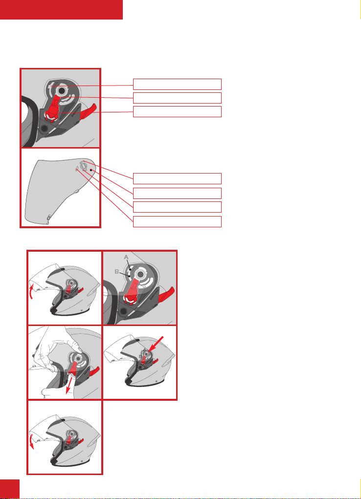
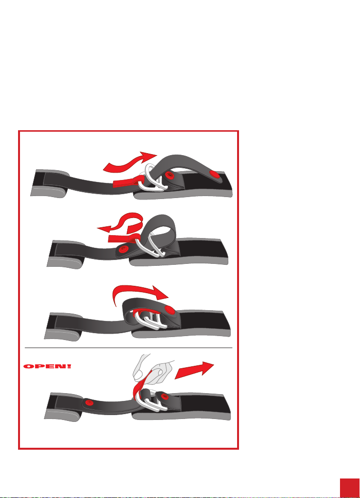
5.1) Azionamento schermo parasole
Per azionare lo schermo parasole basta utilizzare la
levetta posizionata sul lato sinistro del casco a livello
del meccanismo visiera. Per abbassare lo schermo
parasole, spingere verso l’alto la levetta (1). Per far
scomparire lo schermo parasole, spingere verso il
basso la levetta (2).
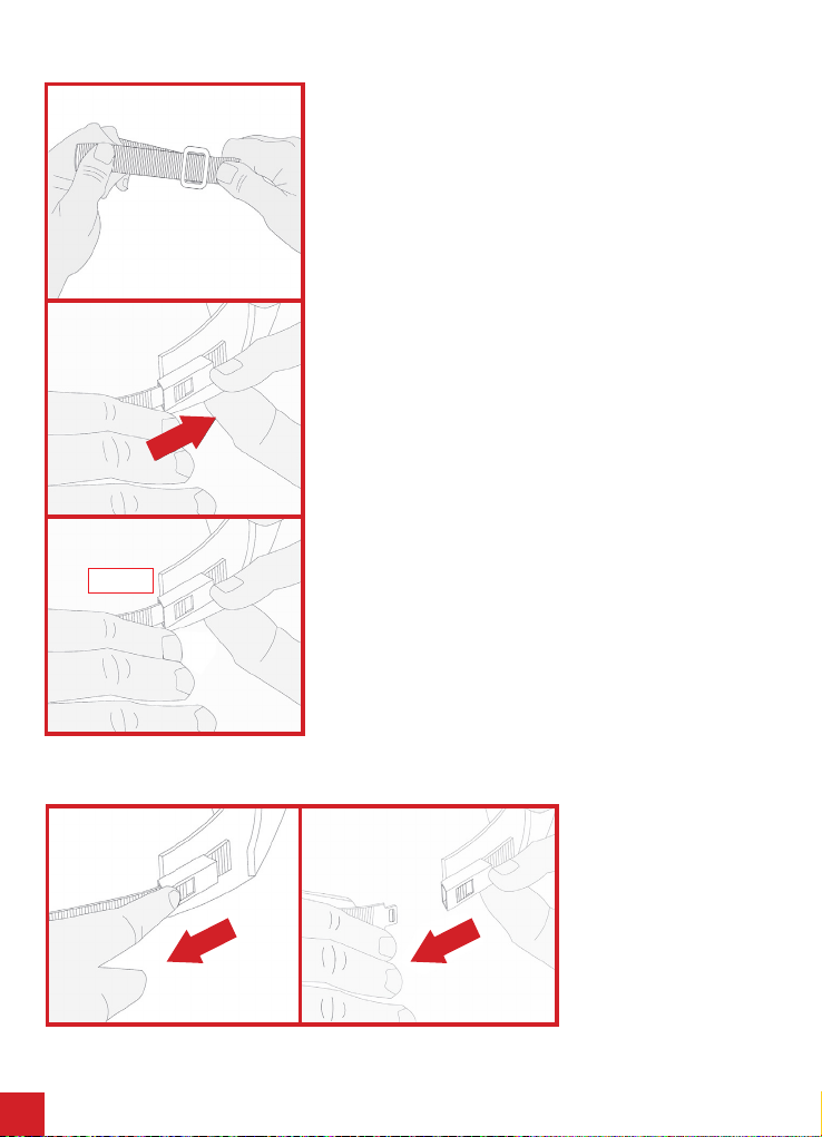
5.2) Rimozione/ Installazione schermo parasole
Lo schermo parasole è in policarbonato antigrafo ed
è dotato di innesti che si inseriscono nelle sedi interne
poste a lato dei guanciali.
Vi consigliamo di eseguire le operazioni che se-
guono appoggiando il casco su una supercie
piatta.
Per rimuovere lo schermo parasole, abbassarlo com-
pletamente e sollevare la visiera no alla totale apertu-
ra (1). Partendo da un lato del casco, fare una leggera
pressione a lato dello schermo parasole verso l’interno
ed estrarre l’innesto di aggancio (2). Ripetere l’opera-
zione anche dall’altro lato e rimuovere il visierino.
1
DOWN
UP
2
DOWN
UP
NB: Una volta estratto da un lato, non tirare o forzare il visierino in una direzione diversa rispetto a quella
orizzontale della guida per estrarlo anche dall’altro lato.
Per installare lo schermo parasole occorre abbassare la levetta di azionamento del visierino ed assicurarsi che le
guide laterali siano in posizione abbassata.
N.B. La guida sinistra si aziona con la levetta posizionata sul lato esterno del casco. La guida destra si può
abbassare manualmente (3).
Partendo da un lato del casco, con la visiera completamente sollevata, inserire l’innesto dello schermo parasole
nella sua sede laterale assicurandosi che poggi sulle guide laterali (4). Ripetere l’operazione anche dall’altro lato.
Vericare il buon funzionamento dello schermo parasole.
1 2
DOWN
UP
DOWN
UP
DOWN
UP
3 4

11
DOWN
UP
1
2
English
1) VISOR
Upper catch seating
Upper catch
Visor tooth
Visor lock
Lower catch
Visor lock slider
1.1) Removing/tting the visor
The non-scratch polycarbonate visor is tted with catches which click into
the visor mechanism base. The visor tooth interact with the teeth on the
mechanism base to provide stability when the visor is open in different
To remove the visor, raise it to the intermediate posi-
tion (1): that position is such that the visor hook (A) is
aligned with the notch on the groundplate (B) (2). Start
on one side of the helmet by pulling the visor lock slider
(3) downwards and detach the catches from the visor.
Repeat on the other side and remove the visor.
To t the visor, start on one side of the helmet, align the
visor hook (A) to the notch on the groundplate (B) and
at the same time insert the upper catch into its seating
on the mechanism base (4). Next, insert the visor lower
catch into the visor lock (pulling the slider downwards
may help) (5). Repeat on the other side of the helmet.
Lower the visor and make sure it is working properly.
Moreover check that the visor when closing will t in its
correct position, that is the magnets and the centering
teeth on the lower side of visor will enter perfectly in
their places.
K-5 Jet
THIS HELMET’S SHELL IS MADE OF COMPOSITE FIBER
THIS HELMET’S LINER IS MADE OF POLYSTYRENE (EPS)
We recommend that you carry out the following tasks with the helmet resting on a level surface.
11
Visor pin
N.B. It the visor does not line up properly with the rubber seal on the helmet,
you may need to adjust or replace the visor mechanism base. In such case,
contact AGV for assistance.
DOWN
UP
DOWN
UP
1 2
3 4
5
DOWN
UP
DOWN
UP
A
B
DOWN
UP
A
B

12
2) VENTILATION SYSTEMS
2.1) Opening/closing the front vents
To open/close the front air vents, push the slider until you
hear it click which indicates it is locked in position (1-2).
Polystyrene ducting
Front air vents
Upper air extractor
2.2) Opening/closing the rear air extractor
To open/close the rear air vents push the central slider
DOWN
UP
2
1
Closed
Open
Open
Closed Slider
Open
Closed Slider
Slider

13
3.1) Removing/tting cheek pads
To remove the cheek pads, hold them in front near the
chin guard and pull them in the direction of the arrow
to free them from the press studs (1). Slide the plastic
ap out of its position and remove the cheek pads (2).
To ret the cheek pads, slide them into the helmet,
slide the plastic ap into position on the side of the
helmet (3) and fasten them into place with the press
studs (4).
Make sure that the cheek pads are properly fastened
to the helmet.
3) INTERNAL COMPONENTS
Crown pad
Cheek pads
VVVVVV
VVVVVV
VVVVVV
VVVVVV
VVVVVV
VVVVVV
VVVVVV
VVVVVV
VVVVVV
VVVVVV
VVVVVV
1 2
3 4

14
3.2) Removing/Fitting ear cushion
In the manual bag there is a couple of ear cuchions to
be installed on the cheek pads (1).
The ear cushion is installed on the cheek pad cen-
tering its holes with the buttons on the cheek pad as
shown in the gures (2).
Then apply the cheek pad inside the helmet as de-
scribed above.
After mounting the ear cushion, it is like in above g-
ure (4).
Proceed in the same way for the other side.
For removal, disengage the cheek pad from the but-
tons, remove the ear cushions and assemble again the
cheek pads.
Make sure that the cheek pads are properly fastened
to the helmet.
1
3
2
4With
Without
!
Important for the safety of your helmet
Before attaching the cheek-pads to the skullcap,
pass both chinstrap tapes through the slots pro-
vided in the cheek-pad (see photo “CORRECT”).
An incorrect assembly (photo “WRONG 1” and
“WRONG 2”) will reduce the rotational stability of
the helmet and may increase the risk of the hel-
met coming off in an accident.
VVVVVVVV
VVVVVVVV
VVVVVVVV
VVVVVVVV
VVVVVVVV
VVVVVVVV
1
2

15
3.3) Removing/Fitting the crown pad
To remove the crown pad, undo the buttons at the front (1) then at the rear (2).
Reverse the process to t the pad.
3.4) Removing/Fitting the air lter
Inside the bag containing the instructions, you will also
nd a mesh to be tted to the front opening on the
crown pad.
To lter the air entering the helmet, simply fasten the
mesh in place using the Velcro fasteners provided.
VVVVVV
VVVVVV
VVVVVV
VVVVVV
VVVVVV
VVVVVV
2
1
12
3

16
4) FASTENING SYSTEMS
1
2
3
4.1) DD ring fastening
To fasten the helmet, pass the
strap between the two rings (1),
pull the end of the strap (2) until
the belt presses against your jaw
and fasten the press-stud (3), as
shown in the diagram.
Check that the helmet is secure
(see also the section entitled
“Choice of appropriate helmet” in
the “Safety Warning” booklet).
To loosen the helmet, undo the
press-stud by pulling the end of
the strap and loosen the strap
through the rings, using the red
tab, as shown in the diagram.
There are three types of fastening systems:
- DD ring fastening
- Quick release mechanism
- Micrometric fastener
Below are the instructions for using these three systems.

17
1
2
3
4 5
CLICK!
4.2) Quick release buckle mechanism
The quick release buckle mechanism requires the adjustment of the
strap before fastening.
Following the diagram below, adjust the length of the strap by increasing
or reducing the amount of strap that goes through the metal clasp (1)
until the helmet feels snug when the buckle is fastened.
To fasten the helmet, insert the quick release clasp into the buckle (2)
until it clicks into place (3).
Check that the helmet is secure (see also the section entitled “Choice
of appropriate helmet” in the “Safety Warning” booklet).
To loosen the helmet, press on
the red button (4) to open the
buckle and then pull the clasp
out (5) as shown in the diagram
below.

18
4.3) Micrometrically
adjustable strap retention
system
The micrometrically adjustable
strap retention system needs the
strap to be adjusted for length
before being fastened.
The following instructions and
diagrams show you how to
adjust the length of the strap by
increasing or decreasing the
amount which passes through
the ring (1) until the helmet ts
perfectly with the strap fastened.
To fasten the helmet, insert the
pronged section into the buckle
(2) and press it rmly home (3)
until you feel the strap pressing
against your jaw. The micrometric
adjustment system allows even
N.B. THE PRESS STUDS/VELCRO ON THE RETENTION SYSTEM ARE NOT FOR
FASTENING THE HELMET BUT ONLY TO PREVENT FLAPPING: THEY MUST NOT BE
USED AS AN ALTERNATIVE FOR FASTENING THE STRAP.
more precise “calibration” of the strap for improved comfort thanks to the
number of settings available (We recommend however that you insert the
strap as far into the buckle as possible).
Make sure that the helmet ts your head perfectly (also see “Choosing the
right helmet” in the “Safety Warning” booklet).
To unfasten the helmet, lift the red lever with the help of the fabric tape (4)
then slide the strap out of the buckle (5).
12
34
5

19
5) ACCESSORIES
An inner sun visor is available for the K-5. This visor
can be operated from the outside, retracts when not
in use and can be easily removed for cleaning or
replacement without need of any special tools.
5.1) Operating the sun visor
To raise or lower the sun visor, simply use the lever
on the left side of the helmet near the main visor
mechanism.
To lower the sun visor, push the lever up (1). To retract
the sun visor, push the lever down (2).
5.2) Removing/tting the sun visor
The non-scratch polycarbonate sun visor is tted with
catches which mesh with internal teeth alongside the
cheek pads.
We recommend that you carry out the following
tasks with the helmet resting on a level surface.
To remove the sun visor, lower it fully then raise
the visor to the fully open position (1). Start on one side
of the helmet by pressing the sun visor gently inwards
then release the catch (2). Repeat on the other side
and remove the sun visor.
1
DOWN
UP
2
DOWN
UP
1 2
DOWN
UP
DOWN
UP
DOWN
UP
3 4
NB: When you have removed one side, do not pull or force the sun visor in any direction other than the
horizontal plane of the guide to remove the other side.
To t the sun visor, place the operation lever in the lower position and make sure that the lateral guides are in the
lowered position.
N.B. The left guide is operated with the lever on the outside of the helmet. The right guide can be lowered
manually (3).
Start on one side of the helmet with the visor fully open, insert the sun visor catch into place in the lateral position
and make sure that it is sitting on the lateral guides (4). Repeat on the other side of the helmet. Make sure that the
sun visor is working properly.

DOWN
UP
1
2
20
DOWN
UP
DOWN
UP
1 2
3 4
5
DOWN
UP
DOWN
UP
A
B
DOWN
UP
A
B
Nous vous conseillons d’exécuter les opérations suivantes en posant le casque sur une surface plate.
Français
1) VISIÈRE
Logement crochet supérieur
Crochet supérieur
Cran de la visière
Blocage de la visière
Crochet inférieur
Curseur d’arrêt de la visière
1.1) Démontage/remontage de la visière
La visière est fabriquée en polycarbonate antirayures, et dotée de crochets qui
s’insèrent dans les logements de la base du mécanisme de rotation. Le cran
de la visière agit sur les crans de la base du mécanisme pour permettre à la
visière de rester ouverte dans différentes positions.
Pour retirer la visière, la soulever jusqu’au cran in-
termédiaire d’ouverture (1) : cette position permet au
cran de xation A d’être aligné avec le logement in-
tégré dans le mécanisme B (2). En partant d’un des
deux côtés du casque, tirer vers le bas le curseur de
blocage de la visière (3) et extraire les crochets de la
visière. Répéter cette opération de l’autre côté et en-
lever la visière.
Pour installer la visière, en partant d’un des côtés du
casque, aligner le cran de xation A avec le logement
sur le mécanisme B, et insérer simultanément le cro-
chet supérieur de la visière dans son logement, à la
base du mécanisme de mouvement (4). Ensuite, in-
sérer le crochet inférieur de la visière dans le blocage
de la visière, (en tirant sur le curseur vers le bas pour
faciliter l’opération) (5). Répéter cette opération de
l’autre côté. Abaisser la visière et vérier qu’elle fon-
ctionne correctement.
Contrôler également que la visière se positionne par-
faitement en phase de fermeture, c’est-à-dire avec les
aimants et les crans de centrage situés sur le côté in-
térieur de la visière, parfaitement insérés dans leurs
logements.
K-5 Jet
THIS HELMET’S SHELL IS MADE OF COMPOSITE FIBER
THIS HELMET’S LINER IS MADE OF POLYSTIRENE (EPS)
Goujon de visière
N.B. En cas de mauvaise adhérence de la visière au prol du bord en ca-
outchouc du casque, le réglage ou le remplacement de la base du mécanisme
de la visière pourrait s’avérer nécessaire. Dans ce cas, s’adresser à un point
d’assistance AGV.
This manual suits for next models
7
Table of contents
Languages:
Other AGV Motorcycle Accessories manuals
Popular Motorcycle Accessories manuals by other brands

DYNATEK
DYNATEK DDK2-10 installation instructions

Race Dynamics
Race Dynamics PowerTRONIC Himalayan 452 installation manual

3M
3M Speedglas G5-02 User instructions

Whelen Engineering Company
Whelen Engineering Company LINZ6 installation guide

hepco & becker
hepco & becker Sportrack quick start guide

Happy Trails
Happy Trails HTP5-2-70 quick start guide