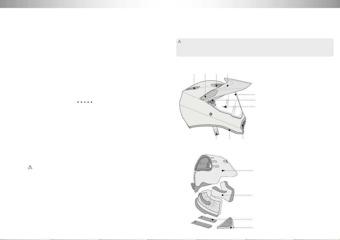
THE INNER COMPONENTS
Reference images on page 73
The interior of the AX9 helmet consists of: two side cheek pads connected to the
neck roll, the upper crown pad, the wind protection and the chin guard cover. These
components can be removed and washed individually.
We recommend that their installation and removal are carried out sitting down, placing the helmet
on your legs.
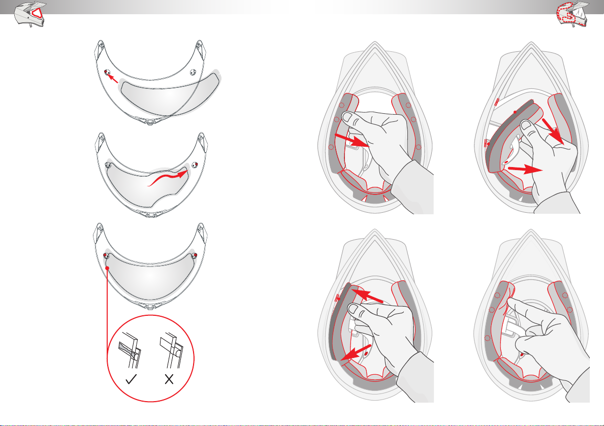
THE CHEEK PADS AND THE NECK ROLL: REMOVAL AND INSTALLATION
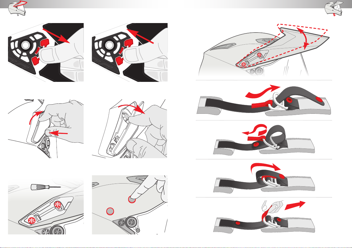
To remove the cheek pads and the neck roll, hold them at the front near the chin guard and pull
them towards the centre of the helmet to release the 6 press studs (img. 06). Remove the plas-
tic strap between the outer shell and the polystyrene shell, releasing it from the 4 red hooks
(img. 07). Slip off the chin strap through the appropriate hole.
To replace the cheek pads and the neck roll, place them inside the helmet, slipping the chin guard
through the appropriate hole, and insert the plastic strap between the outer shell and the polysty-
rene shell, securing it with the 4 red hooks (img. 08). Then secure the cheek pads to the polysty-
rene shell with the 6 press studs (img. 09). Make sure that the cheek pads are properly secured
to the helmet.
Please note! Make sure that the plastic strap is centred correctly and inserted between the in-
ternal polystyrene and the outer shell, to avoid the formation of creases in the fabric.
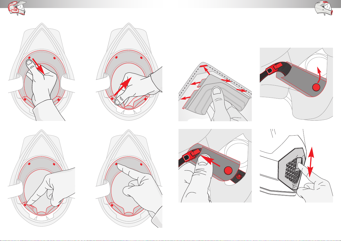
THE CROWN PAD: REMOVAL AND INSTALLATION
To remove the crown pad, release the 2 press studs on the front (img. 10) and the 2 press studs on
the rear (img. 11). Then remove the crown pad from the shell.
To install the crown pad, insert it in the shell and secure it with the 2 rear press studs (img. 12) and
the 2 front press studs (img. 13).
Please note! Before removing the crown pad, make sure to release all the press studs, to avoid
unpicking the fabric components.
THE WIND PROTECTION: INSTALLATION AND REMOVAL
In order to install the wind protection, first insert the front plastic tooth in the bottom section of
the chin guard and then continue with inserting the other side teeth (img. 14). Make sure that the
wind protection is solidly attached to the chin guard.
To remove the wind protection, release it by pulling it down.
THE CHIN STRAP COVER: REMOVAL AND INSTALLATION
To remove the cover, release the press stud that joins it to the chin strap (img. 15) and then slip it
off (img. 16). For the reinstallation, refit it so that it covers the chin guard. Once this has been done,
secure it using the appropriate press stud.
WASHING THE INNER COMPONENTS
After removing them from the helmet, the inner components must be hand washed by immersing
them in warm water with laundry detergent. Rinse with running water. Do not squeeze them and
let them dry at ambient temperature away from direct sun.
THE AIR INTAKES
Reference images on page 75
The AX9 helmet requires appropri-
ate air intakes that when desired will
ensure an efficient air flow even with
the visor completely closed.
The front air intakes and the chin
guard intakes can be opened and
closed as desired, while the rear ex-
tractors, the only object of which is
to allow air to escape from inside the
helmet, are always open, allowing air
to escape at a rate proportional to the
increase of the travelling speed.
We recommend that their installation and removal are carried out sitting down, placing the helmet
on your legs.
THE EXTERNAL CHIN GUARD AIR INTAKE
Lower the slider to open the external chin guard air intake. Lift the slider to close it (img. 17).
To remove the external chin guard air intake, release the button at the bottom of the same (img. 18)
by pulling it up, and rotate the air intake until it is completely detached (img. 19).
To install the external chin guard air intake, this must first be inserted in its upper housing, and
then in the bottom one (img. 20), until a click is heard, which confirms its secure and safe instal-
lation (img. 21).
THE INTERNAL CHIN GUARD AIR INTAKE
Lift the slider to open the internal chin guard air intake. Lower the slider to close it (img. 22).
To remove the internal chin guard air intake, release the button at the top of the same by pulling it
down, and move the air intake down until it is completely detached (img. 23).
To install the internal chin guard air intake, this must first be inserted in its bottom housing, and
then in the top one, until a click is heard, which confirms its secure and safe installation.
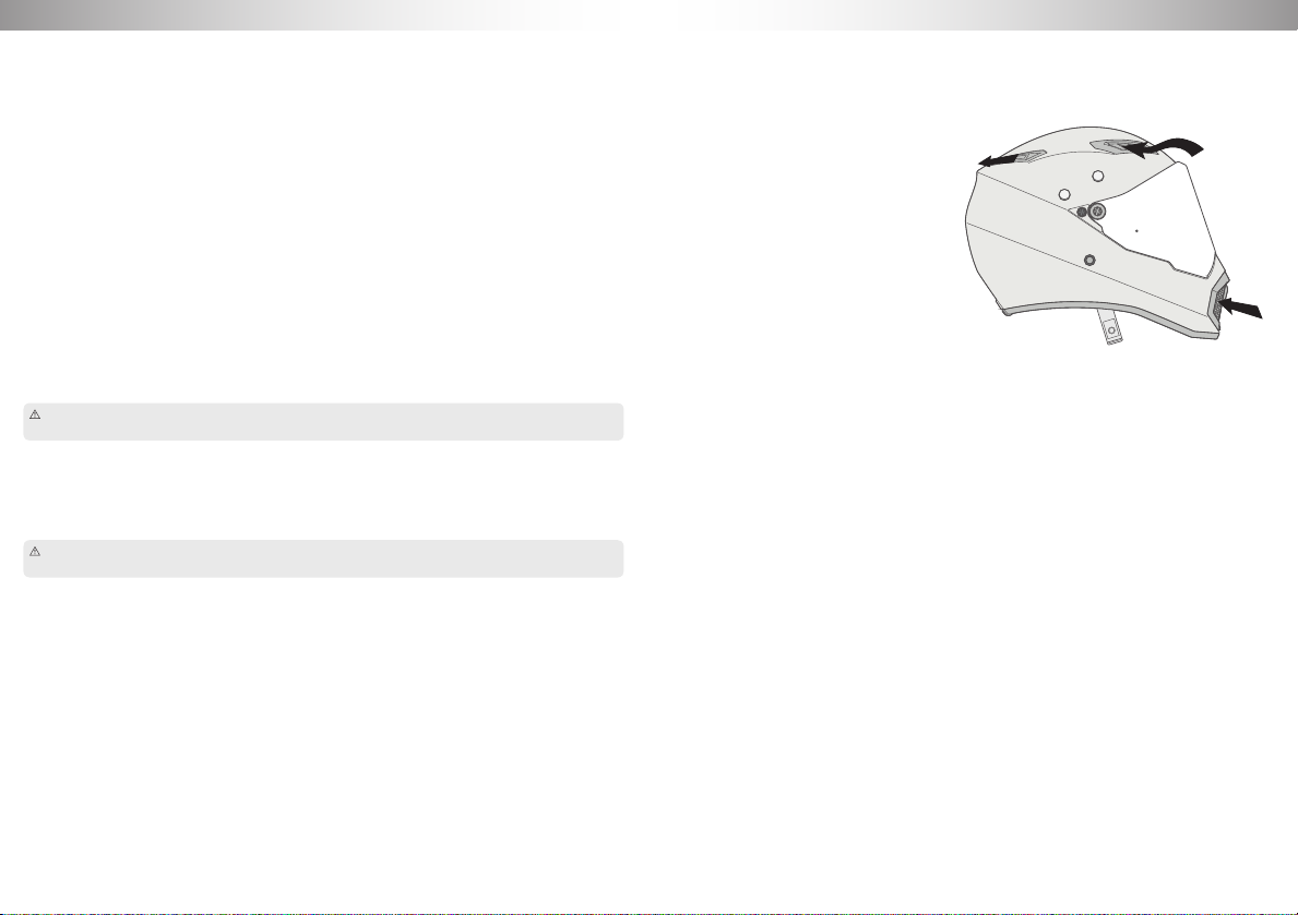
THE FRONT AIR INTAKES
The helmet has two air intakes on the front, above the visor.
Their opening or closing is ensured by a sliding mechanism: to open the air intakes simply push the
slider up, while for closing them simply push the slider down (img. 24).