7
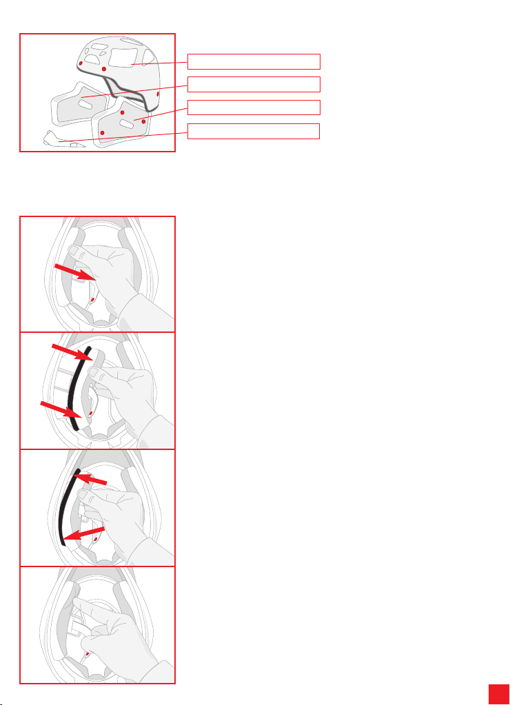
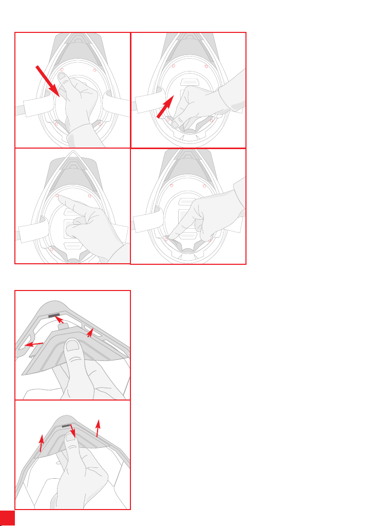
Per rimuovere la cuffia, sgan-
ciare i 2 bottoni automatici
posti nella zona anteriore (1)
ed i 2 nella zona posteriore
del casco (2). Rimuovere la
cuffia dal casco.
N.B. Estrarre la cuffia solo
DOPO avere sganciato tutti
i bottoni automatici di fis-
saggio per evitare di dan-
neggiare i bottoni stessi e di
scucire le parti in tessuto.
Per rimontare la cuffia, inse-
rirla all’interno del casco e fis-
sarla agganciando i 2 bottoni
posteriori (4) ed i 2 bottoni
anteriori (3).
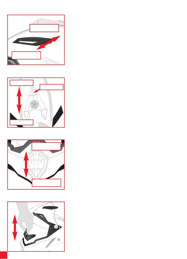
Per installare la protezione sottogola, inserire prima il dente in
plastica anteriore nell’apposita sede sulla mentoniera e proce-
dere poi con l’inserimento dei due denti laterali (1). Verificare
che la protezione sottogola sia ben fissa alla mentoniera.
4) SISTEMA DI RITENZIONE
Ci sono tre tipi di sistemi di ritenzione:
- DD
- Fibbia a sgancio rapido
- Regolazione Micrometrica
Di seguito vengono riportate le indicazioni di utilizzo di tutte queste tipologie.
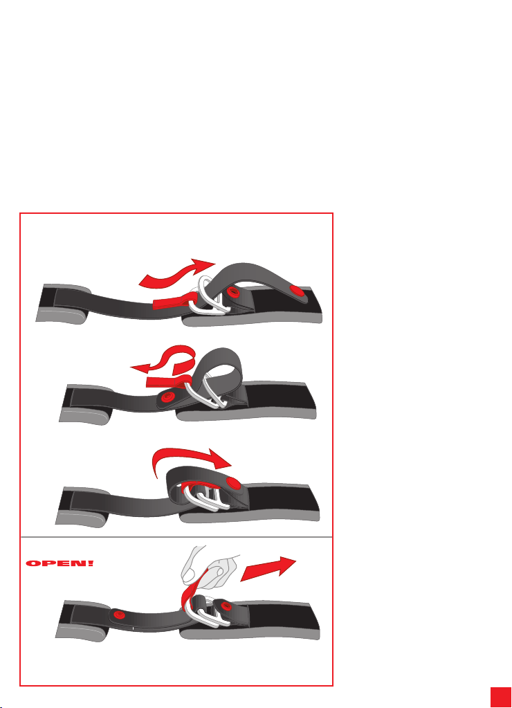
4.1) Sistema di ritenzione DD
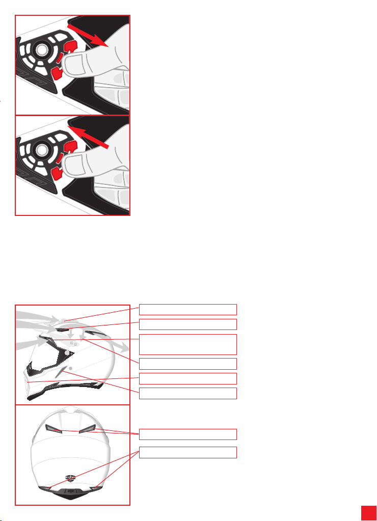
Per allacciare il casco, passare
il nastro tra i due anelli (1), tirare
la parte terminale del nastro
(2) fino a sentire il cinturino
premere contro la mascella
ed agganciare il bottone auto-
matico antisventolio (3), come
indicato in figura.
Verificare che il casco rimanga
ben saldo in testa (vedere an-
che il paragrafo “Scelta del
casco appropriato” del libretto
“Safety Warning”).
Per slacciare il casco, sgan-
ciare il bottone automatico
tirando il terminale del nastro
ed allentare il nastro sfilan-
dolo dagli anelli, aiutandosi
con la linguetta rossa, come
indicato in figura.