manuals.online logo
Brands
  1. Home
  2. •
  3. Brands
  4. •
  5. Anderson
  6. •
  7. Farm Equipment
  8. •
  9. Anderson RBMPRO Setup guide

Anderson RBMPRO Setup guide

DIAGNOSTIC GUIDE FOR RBMPRO
When navigating the pages you will see buttons that send you to the
corresponding procedures / sections of the troubleshooting table. You can also
use the shortcuts from the table of contents (procedures) to obtain a specific
procedure. At any time you may click on the Anderson logo at the top of any
page to return to this page.
1
2
Table of contents
First start maintenance guide A-RBM-000
Hydraulic Diagram A-RBM-001
Manual valve levers and functions A-RBM-002
Hydraulic configurations (load sensing) A-RBM-003
Connecting to the tractor (electric) A-RBM-004
Connecting to the tractor (Hydraulic A-RBM-005
Connecting to the tractor (hitch height) A-RBM-006
Solenoid problem A-RBM-007
Adjusting the pusher stroke A-RBM-008
Adjusting the bale grabber arm height A-RBM-009
Horizontal pick up procedure A-RBM-010
Loading on uneven ground A-RBM-011
Adjusting the angle of the grabber A-RBM-019
Grabber trigger adjustment A-RBM-013
Controller Main Page A-RBM-014
Reset or adjust bale count A-RBM-015
Adjusting the trailer deck width A-RBM-016
Adjusting the cone guide rollers A-RBM-017
Unloading tips A-RBM-018
Sensor locations and functions A-RBM-019
A-RBM-020
A-RBM-021
A-RBM-008
A-RBM-023
Adjusting the wrist Sensor (in case defective) A-RBM-024
Tips to load the 3rd row bales A-RBM-025
Controller icon list A-RBM-026
Controller fuse location A-RBM-027
Indicator status in on diagnostic page in normal condition
–Loading vertical bale seating on flat side A-RBM-028
–Loading Horizontal bale seating on their curved edge A-RBM-029
Understanding the screen message restriction A-RBM-030
RBMPRO 1400
RBMPRO 2000
Bale carrier
Diagnostic procedure
Hydraulic
functions of the
RBMPRO do not
work or hydraulic
hoses can not be
connected
Click here to
continue
Problem with
loading arm
functions or
manner of
loading bales
Click here to
continue
Trouble with
stacking second
row bales
Click here to
continue
Plastic tearing
on bales
Click here to
continue
Problem while
unloading bales
on the ground
Click here to
continue 3
Computer
issues (black or
flashing
screen/red light
indicator is lit)
Click here to
continue
Tractor without
load sensing
pump
Click here to
continue
Error “PT_LS”
appearing on
screen
Click here to
continue
Model(s) : RBMPRO
No functions of
the RBMPRO work
Bale carrier
Diagnostic procedure
The RBMPRO doesn’t
work when manually
moving the valve’s hand
levers
The RBMPRO’s functions
work when the valve
lever is engaged
manually, but not
through the Danfoss
Controller
Make sure that your Danfoss Controller is
powered on and properly connected to the
tractor. Be sure that the controller is properly
connected to the RBM trailer.
PROCEDURE REF# A-RBM-004
Cannot connect the
hydraulic hoses to
the tractor, they
seem pressurized,
and they will not
couple.
If an error is shown
on the Danfoss
controller click here.
(page 14)
If there is no error on
the controller there
may be a Security
Valve, Pressure
reducer valve or
Solenoid problem.
PROCEDURE REF# A-
RBM-007
The RBMPRO is equipped with a
« safety valve » that needs to be
powered on in order to allow oil flow
to circulate through the valve.
Model(s) : RBMPRO
Error “PT_LS”
appearing on
screen
Bale carrier
Diagnostic procedure
“PT_LS” sensor located underneath the frame of the machine is an
hydraulic pressure reader sensor. It provide information to the
computer about the internal hydraulic pressure.
Some hydraulic movement of the RBMPRO are free of proximity
sensor in order to read if the arm ias completed it’s movement.
Without proximity sensor to read the position, we therefore use the
internal pressure to provide back to the computer the information if
the cylinder as completed it’s cycle or not.
For example, when we open the loading arm grabber, as there is no
proximity sensor, the computer will engage the corresponding valve
section till the pressure reach 2500 PSI as per the factory setting,
which can be modified through the Danfoss touchscreen controller.
If you received the “PT_LS” error, it mean the RBMPRO could not built
the internal pressure high enough to meet the condition request by
the computer.
Click here to continue
Model(s) : RBMPRO
Error “PT_LS”
appearing on
screen
Bale carrier
Diagnostic procedure
Determining if the pressure built-in buy the tractor meeting working condition
requirement
Model(s) : RBMPRO
Bring the loading arm down, like if you are collecting bale seating vertically,
and hold physically the lever of the valve in order to build up pressure into the
hydraulic system. Take in note the pressure indicated on the monitor.
By default, the pressure on the
pressure gage should reach the
pressure of the relieve valve of the
main valve which is adjusted to 2800
PSI approximately.
Go into the “locked” menu through
the setting of the Dansfoss
touchscreen controller, and make
sure the value of the parameter
“Pression …” is set 250-300 PSI lower
than the maximum pressure readed
on the previous step. Standard
setting from factory is set at 2500 PSI
I’m not reaching 2800 PSI on the
pressure gage.
The tractor pump as lost it’s
efficiency overtime. Then take in
note the maximum pressure you
could built into the hydraulic
system
Top bale will not
sit on top of the
first row
Bale carrier
Diagnostic procedure
Once loaded, the top row bale rolls off and
drops on the loading platform, not allowing
more bales to be loaded
When loading the top row
bale, the bale starts rolling
away or stays stuck in the
grabber when releasing it.
If operating the
RBMPRO’s at a steep
angle while releasing
the bale, use the
« stand-by » mode to
put the loading phase
on hold. Move the
RBMPRO to a level
terrain in order to
resume the loading
sequence.
A-RBM-011
Avoid sharp turns, abrupt starts and
stops while hooked on the RBMPRO.
Use with caution on irregular or slanted
ground
TIP: Reduce space
between previous
bale stack and pusher
to keep the top bale
in place (LS_PO_M1
AND LS_PO_M2)
A-RBM-008
If you are collecting
bales sitting on their
round side, centering
the bales in the
loading arm before
initial contact is
crucial to insure
proper stability
A-RBM-010
Trouble with
stacking second
row bales
Model(s) : RBMPRO
Model(s) : RBMPRO
Problem with
loading arm
Bale carrier
Diagnostic procedure
Loading arm is
dragging on the
ground
When collecting
bales that are sitting
horizontally on the
ground (bales are not
standing on their flat
side), the grabber is
not positioned
perpendicular to the
ground
The bales hit
the loading arm
but it wont pick
them up
automatically.
Click here to
continue
8
When the
grabber
releases the
bales on the
main deck, the
bales do not
roll
perpendicularly
to the trailer
main axis
Click here to
continue
Adjust the loading arm’s
« initial » angle to the
ground through the
Danfoss controller until
the clearance to the
ground is sufficient
A-RBM-009
Adjust the
sensor
«LS_P2_R »
The bales hit
the loading arm
but it wont pick
them up
automatically.
(LS-BA)
Click here to
continue
Model(s) : RBMPRO
The bales hit the loading
arm trigger but it won’t pick
them up automatically.
Bale carrier
Diagnostic procedure
Make sure the
“automatic loading”
mode is engaged on
the controller
The « qty of bales »
shown on the
controller screen says
that the RBMPRO is
fully loaded, but it is
not.
Inspect the sensor
behind the « triggering
plate » of the loading
arm. (LS_BA)
A-RBM-013
The controller did not
recognize that the bales
have been dumped from
the previous load. Reset
the controller Manually
A-RBM-015
9
Consult the DF700
controller page for
more information
A-RBM-014
The trigger located
between the loading
arm grabbers is not
functioning
Model(s) : RBMPRO
Bale carrier
Diagnostic procedure
10
When the grabber releases the bales
on the main deck, the bales do not
roll well to the opposite side (far side
from the loading arm)
Bales are picked up
vertically
Bales are picked up
horizontally
When picking up the bales
on their side you have to
center them in the
grabber
A-RBM-010
Ensure that the bales are entirely in the grabber
and not just pinched by it. Verify loading
settings in the Danfoss control to set the arm in
the correct initial position for picking up bales
on the flat side
A-RBM-009
Model(s) : RBMPRO
Plastic tearing on bales
Bale carrier
Diagnostic procedure
Plastic torn or puncture
signs are located on the
CURVED EDGE of the
bales
Click here to continue
Plastic torn or puncture
signs located on the
FLAT END of the bales
Loading
Excessive pick up speed causes
the bales to drag while grabbing
Make sure you are not exceeding
3km/h when the bale comes in
contact with the loading arm.
Unloading
Unsuitable surface to unload.
Find a smoother area where the
bales can be dropped off without
being damaged.
Model(s) : RBMPRO
Plastic torn or puncture signs
on the CURVED EDGE of the
bales
Bale carrier
Diagnostic procedure
12
During the loading phase, stop from time to time to investigate at what
stage the bales are damaged by the RBMPRO (Loading, sliding on the
rollers or, Unloading)
During Loading
The bales show signs
of damage when
dropped on the
trailer
Click here to continue
While sliding down
the roller bed
The plastic seems to
tear during its
transition from the
front to the rear of
the platform
Click here to continue
During Unloading
No damage is seen
before unloading,
however, damage is
seen once unloaded
on the ground
Click here to continue
Model(s) : RBMPRO
During Loading
The bales show signs of damage
when dropped on the trailer
Bale carrier
Diagnostic procedure
The roller beds are set
too far apart for the
size of the bales,
therefore exposing the
bales to fall in between
the two beds where
there may be some
sharp edges exposed
A-RBM-016
Inspect for any sharp
edges inside the
loading arm grabber
Make sure you are not
exceeding 3km/h when
the bales make contact
with the loading arm.
When the loading arm
initially makes contact
with the bale, it should be
centered in the middle of
the bale. The bale must
not hit the sides of the
bale grabber as it could
cause some damage to the
curved edge if you collect
bales sitting vertically.
A-RBM-010
A-RBM-012
The in-motion loading
system’s rail touches the
bales previously loaded
when loading.
Inspect for any sharp
edges on the side rails or
damaged rollers that could
puncture the wrap
While sliding down the roller bed
The plastic seems to tear during its
transition from the front to the rear of
the platform
Bale carrier
Diagnostic procedure
14
The roller beds are
too close to each
other for the size of
the bales, therefore
squeezing them
between against
side rails and then
tearing the wrap
The roller beds are set too
wide for the bales size
settings. Make sure that your
bales dimension match the
computer settings, and that
your roller beds are set to
the required position
A-RBM-016
The conical roller
mounted on the loading
arm’s side of the trailer
and the one just ahead of
the side rail get in contact
with the bales, tearing
them apart
A-RBM-017
Model(s) : RBMPRO
During Unloading
No damage is seen before unloading,
however, damage is seen once unloaded on
the ground
Bale carrier
Diagnostic procedure
15
Bales are sliding when hitting
the ground during unloading
phase
When pushing the bales off of the platform, make sure to
compensate for the bales sliding backward, by slowly
moving forward with your tractor so that the bales drop
straight down while unloading.
If the ground’s condition doesn’t allow (too bumpy,
rocky) unloading on the round side, then load a
maximum of 14 bales and unload vertically on their flat
end
A-RBM-018
Inspect unloading platform for
sharp edges and observe the
unloading operation to
pinpoint the area causing the
tear
Computer issues (black or
flashing screen/red light
indicator is lit)
Bale carrier
Diagnostic procedure
The screen turns off (black or
flashing) and then back on again
going back to the main menu
The power supplied to the
Danfoss controller is too low.
Make sure the top right corner of
the controller screen shows a
minimum voltage of 12V. Below
that voltage, when engaging any
coil, the voltage will drop below a
critical point where the computer
loses communication, creating
this kind of issue
I have an error message
appearing on the controller
screen, and a red light indicator
is blinking on the controller
screen. Follow the prompts
from the computer. It will
show you where the fault is. If
needed replace the sensor in
question.
16
17
PROCEDURE REF# A-RBM-000
First use maintenance and guide to start up
General
Before using the trailer for the first time, we strongly recommend that
a full physical inspection and a first stationary manual operation
sequence, is completed in order to avoid any problems in the field (see
below for step by step).
First functions test
After the physical lookover has been done you can:
1. Use the hydraulic functions of the tractor and be sure everything
moves correctly
2. On the trailer move the manual levers of the main valve to be sure
that all functions work correctly. See (PROCEDURE REF# A-RBM-
002) for valve functions guide if needed.
3. On the Danfoss controller press the manual mode button and
engage each function remotely)
4. Enjoy! Go get some bales
First Maintenance after first use
After the first operation of the machine we also recommend a full
inspection of the machine to be certain of long life of the wear parts
and be sure there is no premature wear that could cause failure. This
step should be followed before putting the machine to use if it has
been pulled on public or private roads before operation.
18
PROCEDURE REF# A-RBM-001 (hydraulic diagram)
19
PROCEDURE REF# A-RBM-002
Manual valve levers and functions
FUNCTION
DESCRIPTION
1
OPEN ↑ AND CLOSE ↓ THE CLAMP
2
EXTEND ↓ AND RETRACT ↑ PIVOT NO1 OF THE LOADING ARM
3
RAISE ↑ AND LOWER ↓ THE LOADING ARM
4
MOVE FORWARD ↑ AND BACKWARD ↓ ON THE LOADING ARM'S SLIDE
5
EXTEND ↑ AND RETRACT ↓ THE LOADING ARM
6
MOVE FORWARD ↑ AND BACKWARD ↓ THE BALE PUSHER
7
EXTEND ↑ AND RETRACT ↓ PIVOT NO3 OF THE LOADING ARM
8
TURN (CLOCKWISE) ↑ AND TURN (COUNTER
-
CLOWISE) ↓ PIVOT NO 2 OF THE
LOADING ARM
9
RAISE ↑ AND LOWER ↓ THE REAR STOPPERS
20
Hydraulic coupling
Product model Number of
hydraulic outlet
required
Hydraulic function North American coupling
description
European coupling referencial
RBMPRO2000
factory
configuration
(Load sensing)
1
Main valve
pressure line
3/4" male
FASTER: ANV
-34-NPT-M
Main valve return
to the tank
3/4" female
FASTER: ANV
-34-NPT-F
2
Load sensing
3/8" male
FASTER: ANV
-38-NPT-M
3
Tilting unloading
platform
1/2" male
FASTER: 2NV
-1/2-M
Tilting unloading
platform
1/2" male
FASTER: 2NV
-1/2-M
Below configuration are necessary if the tractor pump is NOT load sensing (LS). However, when it is possible it is preferable
to run them with a load sensing tractor for lower oil temperature, and lower restriction when operating more than one
function. The RBMPRO2000 body valve can take up to 20 GPM (80L/min) but we recommend to adjust the flow at 14 GPM
(55L/min). The pressure requested will be in the range of 2900 PSI (200/210 BAR).
NEVER CONNECT THE RBMPRO2000 TO AN OLD TRACTOR NOT EQUIPPED WITH A VARIABLE
DISPLACEMENT PUMP
RBMPRO2000
(If tractor has no
load sensing)
1
Main valve
pressure line
Remove the 3/4" male coupler and the adaptor/reducer 3/4" to
1/2" and replace them by a 1/2" male coupler or European
reference part number is FASTER: 2NV
-1/2-M
Main valve return
to the tank
Remove the 3/4" male coupler and replace by an
expander/adaptor 3/4" to 1/2" (BRENNAN: 5405
-08-12 or
PARKER: 3/4
-X1/2 FG-S) and then mount an 1/2" male coupler
or European reference FASTER: 2NV
-1/2-M
2
Load sensing
No modification needed. The hydraulic hose dedicated to load
sensing can be stored and attached on the trailer .
3
Tilting unloading
platform
1/2" male
FASTER: 2NV
-1/2-M
Tilting
unloading
platform
1/2" male
FASTER: 2NV
-1/2-M
PROCEDURE REF# A-RBM-003 (continued)
Connecting to the tractor (hydraulic) coupling chart

This manual suits for next models

2

Other Anderson Farm Equipment manuals

Anderson GB series User manual

Anderson

Anderson GB series User manual

Anderson RB580 User manual

Anderson

Anderson RB580 User manual

Anderson 680HS User manual

Anderson

Anderson 680HS User manual
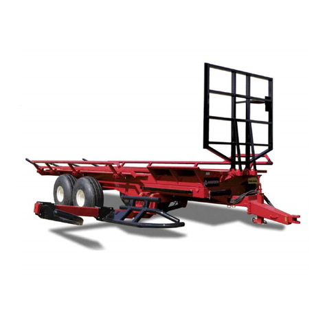
Anderson NutriWrap 780 SB User manual

Anderson

Anderson NutriWrap 780 SB User manual

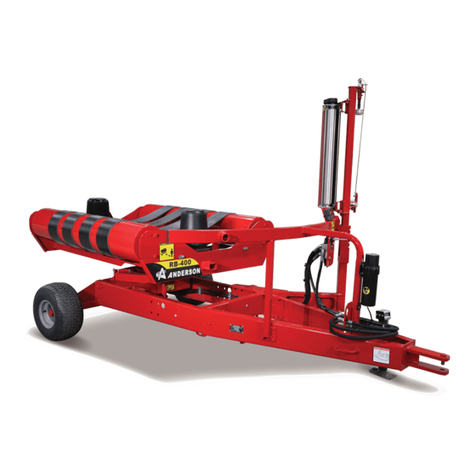
Anderson RB-400 User manual

Anderson

Anderson RB-400 User manual

Anderson Double stretcher User manual

Anderson

Anderson Double stretcher User manual

Anderson ROUND BALE WRAPPER HYBRID User manual

Anderson

Anderson ROUND BALE WRAPPER HYBRID User manual

Anderson RB580 User manual

Anderson

Anderson RB580 User manual

Anderson WRAPTOR User manual

Anderson

Anderson WRAPTOR User manual

Anderson Fusion720 User manual

Anderson

Anderson Fusion720 User manual
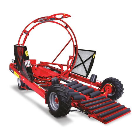
Anderson RBM1400 User manual

Anderson

Anderson RBM1400 User manual

Anderson RB-500 Operator's manual

Anderson

Anderson RB-500 Operator's manual

Anderson RB 680 User manual

Anderson

Anderson RB 680 User manual

Anderson RB-200 User manual

Anderson

Anderson RB-200 User manual

Anderson RB580 User manual

Anderson

Anderson RB580 User manual

Anderson TRB1000 Setup guide

Anderson

Anderson TRB1000 Setup guide
Anderson Hybrid-X Installation guide

Anderson

Anderson Hybrid-X Installation guide
Anderson TSR-3450 User manual

Anderson

Anderson TSR-3450 User manual

Anderson IFX720 Manual

Anderson

Anderson IFX720 Manual

Anderson RB-200 User manual

Anderson

Anderson RB-200 User manual

Anderson STACKPRO Series Setup guide

Anderson

Anderson STACKPRO Series Setup guide

Anderson 680HS User manual

Anderson

Anderson 680HS User manual
Anderson 590HS User manual

Anderson

Anderson 590HS User manual
Anderson M-160 User manual

Anderson

Anderson M-160 User manual

Popular Farm Equipment manuals by other brands

LELY Splendimo 320 M Operator's manual

LELY

LELY Splendimo 320 M Operator's manual

Ogden RCR812 owner's manual

Ogden

Ogden RCR812 owner's manual

Baumalight SWF580 Operator's manual

Baumalight

Baumalight SWF580 Operator's manual

Tektite Kioti CK35 Series Operation manual

Tektite

Tektite Kioti CK35 Series Operation manual

aivituvin AIR 73 instruction manual

aivituvin

aivituvin AIR 73 instruction manual

Land Pride RTR2570 Operator's manual

Land Pride

Land Pride RTR2570 Operator's manual

Monosem NG Plus Me  2017 manual

Monosem

Monosem NG Plus Me 2017 manual

Netafim Fertikit 3G installation manual

Netafim

Netafim Fertikit 3G installation manual

GREAT PLAINS 1007NT Operator's manual

GREAT PLAINS

GREAT PLAINS 1007NT Operator's manual

Raven SmarTrax installation manual

Raven

Raven SmarTrax installation manual

New Holland FR480 Forage Cruiser Service manual

New Holland

New Holland FR480 Forage Cruiser Service manual

Kverneland 150 Series operating manual

Kverneland

Kverneland 150 Series operating manual

Samon SU2M Manual & Parts list

Samon

Samon SU2M Manual & Parts list

Land Pride WB15 Operator's manual

Land Pride

Land Pride WB15 Operator's manual

Toro Sand Pro 140-0274 installation instructions

Toro

Toro Sand Pro 140-0274 installation instructions

Moore Tandem Uni-Drill DP400A instructions

Moore

Moore Tandem Uni-Drill DP400A instructions

ISARIA PRO Compact instruction manual

ISARIA

ISARIA PRO Compact instruction manual

Headsight AGCO MY98-20 Installation & operation manual

Headsight

Headsight AGCO MY98-20 Installation & operation manual

manuals.online logo
manuals.online logoBrands
  • About & Mission
  • Contact us
  • Privacy Policy
  • Terms and Conditions

Copyright 2025 Manuals.Online. All Rights Reserved.