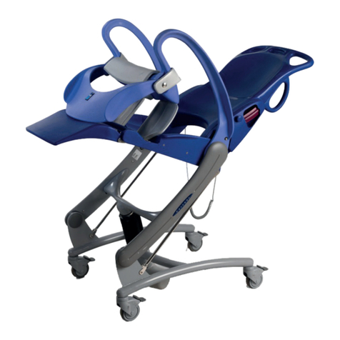
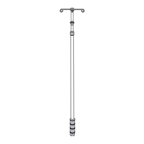
Arjo Lifeguard LG55 User manual

INSTRUCTIONS FOR USE
Lifeguard LG55
746-316-EN_10 • 11/2019

2
WARNING
To avoid injury, always read this Instructions for Use and accompanied documents
before using the product.
Mandatory to read the Instructions for Use.
Design Policy and Copyright
® and ™ are trademarks belonging to the Arjo group of companies.
© Arjo 2019.
As our policy is one of continuous improvement, we reserve the right to modify designs without
prior notice. The content of this publication may not be copied either whole or in part without the
consent of Arjo.

3
Warning and Cautions...................................................................................................................4
Introduction....................................................................................................................................5
Intended Use.................................................................................................................................6
Operation.......................................................................................................................................7
Accessories.................................................................................................................................17
Decontamination..........................................................................................................................19
Care and Preventive Maintenance..............................................................................................20
Warranty and Service..................................................................................................................22
Dimensions and Data..................................................................................................................23
Content

4
WARNING
Means: Safety warning. Failure to understand and
obey this warning may result in injury to you or to
others.
CAUTION
Means: Failure to follow these instructions may
cause damage to all or parts of the system or
equipment.
NOTE
Means: This is important information for the correct
use of this system or equipment.
Serious incident
If a serious incident occurs in relation to this
medical device, affecting the user, or the patient
then the user or patient should report the serious
incident to the medical device manufacturer or the
distributor. In the European Union, the user should
also report the serious incident to the Competent
Authority in the member state where they are
located.
General Warnings
WARNING
The age, size and condition of the patient
should be assessed by a competent
FOLQLFDOO\TXDOL¿HGSHUVRQEHIRUHXVLQJ
the Lifeguard trolley, giving particular
consideration to appropriate use of the
safety sides.
WARNING
If any part is missing or damaged - do
NOT use the product.
WARNING
Do not use accessories that are not
designed or approved for use with the
Lifeguard trolley.
WARNING
Always apply the brakes when the
Lifeguard trolley is stationary.
WARNING
Raise the safety sides before moving the
Lifeguard trolley with a patient.
WARNING
Children and restless or disorientated
patients should not be left unattended at
any time.
WARNING
Before turning (rolling) a patient on the
Lifeguard trolley or performing a lateral
transfer, adjust the mattress platform to
a comfortable working height; be aware
that the Lifeguard trolley may overbalance
if the patient’s weight is not evenly
distributed across the mattress platform.
Warning and Cautions
5
Introduction
This manual gives instruction for the use and
maintenance of the Lifeguard® patient trolleys, model
number LG55. (See Fig. 1)
The Lifeguard trolley has X-ray translucent mattress
platforms. The products also feature a sliding X-ray
cassette tray facility.
Fig. 1

6
Fig. 2
Intended Use
The Lifeguard trolley range is intended for use in
hospitals to provide a mattress support surface and to
transport patients. The Lifeguard trolleys may be used
for general and emergency admissions, examination,
diagnostic X-ray and initial treatment. They are also
appropriate for patient transfer between departments,
wards and theatre.
Lifeguard trolleys must be used by appropriately
trained caregivers with adequate knowledge of
the care environment, its common practices and
procedures, and in accordance with the guidelines in
the Instruction for Use.
The trolleys should only be used for the purpose
VSHFL¿HGLQWKLV,QVWUXFWLRQVIRU8VH$Q\RWKHUXVHLV
prohibited.
Patient/Resident assessment
We recommend that facilities establish regular
assessment routines. Caregivers should assess each
resident/patient according to the following criteria
prior to use:
• To ensure the patient can use the trolley safely,
their age, size and condition should be assessed by a
FOLQLFDOO\TXDOL¿HGSHUVRQ
• The maximum safe working load is:
Lifeguard 55: 250 kg (550 Ibs.) (See Fig. 2)
If the patient/resident does not meet these criteria an
alternative equipment/system shall be used.
Expected service life
The lifetime of this product is typically ten (10) years.
³/LIHWLPH´LVGH¿QHGDVWKHSHULRGGXULQJZKLFKWKH
SURGXFWZLOOPDLQWDLQWKHVSHFL¿HGSHUIRUPDQFHDQG
safety, provided it has been maintained and operated
in conditions of normal use in accordance with the
requirements in the Instructions for Use.

7
Safety
For the safety of operator, patient and equipment:
• Always use a mattress of the correct size and type
for the Lifeguard trolley.
• Do not expose the equipment, especially the
PDWWUHVVWRQDNHGÀDPHVFLJDUHWWHVHWF
• Before operating the Lifeguard trolley, make sure
that the patient is positioned correctly to avoid
entrapment and imbalance.
• When the Lifeguard trolley is operated, check that
no obstacles are in its path.
• Keep these instructions handy for reference.
Mattress
The mattress is secured to the platform by means of
hook and loop tapes on the mattress underside and the
laminate top.
Push Bar Handles
Adjust the height of the handles
(2 Steps) (See Fig. 3)
1. Press the spring-loaded release button (A) and
raise or lower the handle as required (B).
2. Let go of the button to lock the handle in the high
or low position.
Brakes and Steering (See Fig. 4)
There is a pair of linked brake pedals at each end of
the Lifeguard trolley. Push the pedals down to apply
brakes on all castors.
When the pedals are horizontal, the castors are free to
rotate and swivel.
A steering castor is engaged when an optional
WKZKHHOLV¿WWHGDQGWKHSHGDOVDUHIXOO\UDLVHG
In this situation the Lifeguard trolley will keep on a
straight course in any direction and can be steered by
pivoting about the 5th wheel. When the 5th wheel is
QRW¿WWHGWKHVWHHULQJFDVWRULVDWWKHIRRWHQGDQGWKH
Lifeguard trolley should be pushed from the head-end.
Fig. 3
Operation
Fig. 4
Free Brake Steer

8
Height and Tilt Adjustment
Model LG55
The height and the tilt angle of the mattress platform
DUHDGMXVWHGXVLQJDJURXSRI¿YHIRRWSHGDOVRQ
either side of the Lifeguard trolley. The three pedals
marked with a black on the bottom row are used
to raise the platform. The two pedals marked with a
red on the top row are used to lower the platform.
(See Fig. 5)
Title Adjustment (See Fig. 6)
Raise one end of the platform
• Operate the “raise” pedal (black ) nearest that
end of the Lifeguard trolley with a pumping action.
Lower one end of the platform
• Press down on the “lower” pedal (red ) nearest
that end of the Lifeguard trolley and keep it
pressed.
NOTE
There is an additional “lower” pedal (red )
that enables head down tilt to be applied from
the head end of the Lifeguard trolley.
Height Variation
Raise the platform
• Operate the central “raise” pedal (black ) with a
pumping action.
Lower the platform
• Press down both “lower” pedals (red ) and keep
them pressed.
If the platform is raised or lowered when tilted, the tilt
angle will be maintained until the leading end reaches
the limit of travel, when the platform will return to the
horizontal condition.
Fig. 5
Fig. 6

9
Backrest
NOTE
7KHDPRXQWRIHႇRUWQHHGHGWRUDLVHRU
lower the backrest will vary depending on
patient weight and mobility. With a very heavy
patient, the backrest may fall quickly if it is not
supported when released.
Adjust the backrest
(2 Steps) (See Fig. 7)
1. *UDVSWKHKDQGOH¿UPO\SUHVVWKHUHOHDVHNQRE
and lift the backrest assisted by the gas spring or
push it down against the action of the gas spring.
2. Let go of the release knob to lock the backrest at
any angle.
Safety Sides
(See Fig. 8)
Raise the safety side
• Hold the top rail and lift until it locks into position
at maximum height.
Lower the safety side
• Hold the top rail with one hand, pull the release
button at the foot end and lower the rail toward the
head.
In order to accommodate Arm X-ray vision when
taking side-shot X-ray pictures, each safety side
can be lowered even further than its initial resting
position. When the safety side is folded down it rests
on two stops (A) that are located at each end of the
mattress platform side-frame. (See Fig. 9)
WARNING
When the safety side is in the folded
position, the upright bars rest on the two
stops.
Care should be taken to keep hands and
¿QJHUVDZD\IURPWKHVHDUHDV
Fig. 7
Fig. 8
Fig. 9

10
Operation
(4 Steps) (See Fig. 10)
1. Lower the safety side until the upright bars rest
on two white plastic stops.
2. At the head-end of the Lifeguard trolley, position
the thumb over the top rail of the safety side and
XVH¿QJHUVWRSXVKWKHVOLGLQJFDWFK (A), which
is located beneath each side-rail white plastic
stop, in towards the Lifeguard trolley frame as
illustrated (avoid squeezing the rail and catch
together).
CAUTION
Only use the sliding catch (A) to retract
the safety side stop.
CAUTION
Do not use the safety sides to move the
Lifeguard trolley. Only use the push bar
handles to operate the Lifeguard trolley.
3. With the catch fully pushed in, ease the top rail
down to the second position.
4. At the foot-end of the Lifeguard trolley use two
hands, one to hold the top rail and the other to
push the sliding catch (A). Again, once the catch
is fully pushed in, ease the top of the rail down to
its second position.
Reinstate the safety side to normal
position
• Lift the top rail of the safety side at a point
approximately halfway along the Lifeguard trolley.
The stops will automatically spring back to their
original position.
Fig. 10

11
Fig. 11
Fig. 12
Foot end
Head end
X-ray
imaging
area
X-Ray Cassette Drawer Shown Accessed from Patient’s
Left-Hand Side
Mattress Platform Showing Imaging Area
X-Ray Photography
The mattress platform is X-ray translucent. The X-ray
cassette drawer below the mattress platform can be
positioned anywhere along the length of the platform
for full patient coverage. (See Fig. 11) (See Fig. 12)
Load or unload cassettes
• Press the red latch (A) down and use the slot (B) to
pull the cassette drawer out until it reaches its stop
position. (See Fig. 13)
Cassette Drawer Latch
Fig. 13

12
The drawer has recesses to suit two sizes of X-ray
cassette:
• A (390mm x 466mm) (See Fig. 14)
• B (273mm x 334mm) (See Fig. 15)
For each size of X-ray cassette there are two possible
positions, at 90°to each other.
3ODFHWKH;UD\FDVVHWWHÀDWLQWKHDSSURSULDWHUHFHVV
Push the drawer back under the mattress platform
until it latches into place.
The X-ray cassette drawer can be accessed from
either side of the mattress platform. (See Fig. 16)
When the cassette drawer is pushed all the way in to
its latched position, it is centrally located within the
imaging area (A). (See Fig. 16)
A
Fig. 14
B
Fig. 15
Fig. 16

13
2ႇVHWWKHFDVVHWWHGUDZHUIURPWKH
central position (See Fig. 17)
• Pull out the drawer and line up one of the markers
(A,B or C) with the black indicator bar (D).
The markers correspond with the letters next to the
X-ray cassette; e.g. when marker (A) is lined up
with the indicator bar (D), edge (A) of the X-ray
cassette is on the boundary of the imaging area.
(See Fig. 18)
Adjust the position of the X-ray cassette
drawer along the length of the mattress
platform
(2 Steps) (See Fig. 20)
1. Lift the lever and slide the drawer to the desired
position.
2. Release the lever to hold the drawer in place.
Fig. 17
Fig. 18
Fig. 19
Fig. 20
X-Ray Cassette Drawer Lever

14
Oxygen Therapy Equipment
WARNING
Ensure that the oxygen line does not
become entangled or trapped which could
cause damage to the line or loss of supply.
Ensure that when the Lifeguard trolley
is operated it does not collide with the
installed equipment, especially at low
height.
A recess in the base of the Lifeguard trolley will
accommodate a size D, E or F oxygen cylinder.
Rubber pads cushion the cylinder to prevent unwanted
movement.
In addition, facilities are provided for the installation
and use of oxygen therapy systems. A short rail
(Medirail) is provided at the head-end of the
Lifeguard WUROOH\WRDFFRPPRGDWHWKHÀRZPHWHUDQG
injection suction unit. (See Fig. 21)
A universal mounting bracket is installed in the base
of the Lifeguard trolley to accept the suction receiver
jar. (See Fig. 22) If the mounting bracket is not
DOUHDG\¿WWHGUHPRYHWKHSODVWLFFRYHUIURPWKHKROH
in the base cover moulding and attach the bracket
with two 6 mm Button Head screws and nuts using
the pre-drilled holes in the base frame.
Fig. 21
Fig. 22

15
IV Drip Rod MB-ACC32
Install the IV pole in one of the four tubular sockets at
the corners of the platform (A). (See Fig. 24)
WARNING
The maximum total load on the hooks must
not exceed 5 kg.
The maximum load attached to the lower
tube must not exceed 10 kg.
Adjust the height
(5 Steps) (See Fig. 24)
1. +ROGWKHWHOHVFRSLQJ,9SROH¿UPO\
2. Loosen the locking collar (B).
3. Lift or lower the inner IV pole as required (C).
4. 5HWLJKWHQWKHORFNLQJFROODU¿UPO\(D).
5. Fold out the hooks (E).
NOTE
Be careful not to lift the IV pole out of the
socket when raising the hook.
Storage
Adjust the IV pole to minimum length and tighten the
locking collar before storing it in the clips on the base
of the Lifeguard trolley.
Fig. 23
A
B
C
D
E
Fig. 24

16
Integral IV Drip Rod 799.501
The built-in IV pole is located at the head end of the
Lifeguard trolley.
WARNING
Do not exceed the maximum safe load of
5 kg.
Lift the pole to the vertical position (A) and allow it
to drop into the tubular socket on the platform (B).
(See Fig. 26)
Adjust the height
(4 Steps) (See Fig. 26)
1. +ROGWKHWHOHVFRSLQJ,9SROH¿UPO\
2. Loosen the locking collar (C).
3. Lift or lower the hook as required (D).
4. 5HWLJKWHQWKHORFNLQJFROODU¿UPO\(E).
NOTE
Be careful not to lift the IV pole out of the
socket when raising the hook.
Storage
Adjust the pole to minimum length and tighten the
locking collar, then lift the pole out of the socket and
fold it down.
Fig. 25
E
AB
C
D
Fig. 26

17
Accessories
A range of accessories, including mattresses, is available from Arjo. Details are
available on request.
Accessories currently available for Lifeguard LG55 are shown in the table below.
ACCESSORY NAME PRODUCT CODE
Loose drip rod 157003
Foot end panel & bow 157009
Foot panel with monitor table 157018
Clip-on table 157021
Arm rest 157006PE02
Safety side pads (grey) 99901PE16
DIN rail kit (head end) LG/ACC03
Oxygen bottle holder (PD size) LG/ACC04
DIN rail kit (foot end) LG/ACC05
Mattress with two-way stretch cover - 65 mm thick LGMAT/10
Mattress with two-way stretch cover - 80 mm thick LGMAT/12
Two part transfer mattress LGMAT/13
Two part transfer mattress "Pennyla" LGMAT/13PN
Bi-Flex pressure reducing mattress TRM2
Bi-Flex pressure redistribution mattress TRM3
Some accessories may not be available in all markets. Arjo reserves the right to
DOWHUVSHFL¿FDWLRQVDQGDYDLODELOLW\ZLWKRXWQRWL¿FDWLRQ
The following information relates to accessories supplied with the Lifeguard
trolley. Other accessories are supplied with instructions for use.
LGMAT/10
The LGMAT/10 is a one piece mattress with two-way stretch anti-static PU cover,
used to provide the patient with adequate comfort during transport and to facilitate
cleaning and disinfection.
LGMAT/12
The LGMAT/12 is a one piece, twin-foam mattress with two-way stretch anti-
static PU cover, used to provide the patient with increased comfort during
transport and to facilitate cleaning and disinfection.
LGMAT/13
The LGMAT/13 transfer mattress is designed to allow patients to be moved easily
and with minimal discomfort from a Lifeguard trolley to an adjacent surface.

18
Foot Panel with Monitor Table
157018
Install the foot panel in the square sockets at the end
of the mattress platform, with the clipboard on the
outside.
WARNING
Maximum safe working load 12 kg evenly
distributed.
Use the monitor table
(2 Steps) (See Fig. 28)
1. Place the clipboard in a horizontal position.
2. Use the straps to secure the monitor to the table.
Remove the foot panel
• Lift it out of the sockets.
Fig. 27
Fig. 28

19
Decontamination
The following processes are recommended,
but should be adapted to comply with the local
or national guidelines (Decontamination of
Medical Devices) which may apply within
the Healthcare Facility or the country of use.
If you are uncertain, you should seek advice
from your local Infection Control Specialist.
The Lifeguard system should be routinely
decontaminated between patients and at
regular intervals while in use; as is good
practice for all reusable medical devices.
WARNING
Protective clothing should always
be worn when carrying out
decontamination procedures.
CAUTION
Do not use Phenol-based solutions
or abrasive compounds or pads
during the decontamination process
as these will damage the surface
coating. Do not boil or autoclave the
cover.
Clean
(2 Steps)
1. Clean all exposed surfaces and remove
any organic debris by wiping with a
cloth moistened with a simple (neutral)
detergent and water.
2. Dry thoroughly.
Chemical disinfection
(4 Steps)
To protect the integrity of the cover we recommend a
chlorine-releasing agent, such as sodium hypochlorite,
at a strength of 1,000ppm available chlorine (this may
vary from 250ppm to 10,000ppm depending on local
policy and contamination status).
1. Wipe all cleaned surfaces with the solution, rinse
and dry thoroughly.
2. Alcohol based disinfectants (maximum strength
70%) may be used as an alternative.
3. Ensure the product is dry before storage.
4. If an alternative disinfectant is available and
selected from the wide variety, we recommend
WKDWVXLWDELOLW\IRUXVHLVFRQ¿UPHGZLWKWKH
chemical supplier prior to use.
Clean the mattress
(2 Steps)
1. Wipe all surfaces with a disposable cloth soaked
in a neutral detergent and hand hot water.
2. Rinse with clean water and dry with disposable
paper towels.
Disinfect the mattress
• Wipe all surfaces with a solution of sodium
dichloroisocyanurate (NaDCC) at a concentration
of 1,000ppm (0.1%) available chlorine.

20
Care and Preventive Maintenance
This product is subject to wear and tear during use. To ensure that it continues
WRSHUIRUPZLWKLQLWVRULJLQDOVSHFL¿FDWLRQSUHYHQWLYHPDLQWHQDQFHSURFHGXUHV
should be carried out at the intervals shown.
WARNING
This list indicates the minimum level of preventive maintenance
recommended by the manufacturer. More frequent inspections
should be carried out when the product is subjected to heavy use
or aggressive environments, or where required by local regulations.
Failure to carry out these checks, or continuing to use the product if
a fault is found, may compromise the safety of both the patient and
carer/user. Preventive maintenance can help to prevent accidents.
Actions to be done by carer/user Daily Weekly Yearly
Clean and disinfect as shown in
“Decontamination” on page 19. X
Check operation of safety sides X
Visually check castors X
Inspect the mattress as described on the
next page X
&KHFNVDIHW\VLGHSDGVLI¿WWHG X
If the result of any of these tests is unsatisfactory, contact Arjo or an approved
service agent.
WARNING
The procedures below must be carried out by suitably trained and
TXDOL¿HGSHUVRQQHO)DLOXUHWRGRVRPD\UHVXOWLQLQMXU\RUDQ
unsafe product.
Actions to be done by carer/user Daily Weekly Yearly
Check the operation of the lifting
mechanism as described below X
Check the operation of the backrest raise
and lower X
Check operation of castors, paying special
attention to braking and steering functions X
Check the hydraulic pump for leaks X
Check all nuts, bolts and other fasteners
are present and correctly tightened X
Check all accessories, paying particular
attention to fasteners and moving parts X
Table of contents
Other Arjo Medical Equipment manuals

Arjo
Arjo Flowtron ACS900 User manual

Arjo
Arjo MaxxAir ETS User manual

Arjo
Arjo Auralis User manual

Arjo
Arjo MAA6000 User manual

Arjo
Arjo Bolero User manual

Arjo
Arjo Enterprise ENT-ACC32 User manual

Arjo
Arjo Alpha Active User manual

Arjo
Arjo MAA8000 User manual

Arjo
Arjo Evenda EV-ACC05 User manual

Arjo
Arjo MAA4020M User manual

Arjo
Arjo Enterprise ENT-ACC02 User manual

Arjo
Arjo Malibu User manual

Arjo
Arjo Concerto electric Installation guide

Arjo
Arjo LGMAT/13 User manual

Arjo
Arjo Maxi Sky 2 PLUS User manual

Arjo
Arjo Maxi Sky 2 User manual

Arjo
Arjo MLAAS2000 User manual

Arjo
Arjo Parker User manual

Arjo
Arjo Citadel User manual

Arjo
Arjo Pentaflex User manual